> For the complete documentation index, see [llms.txt](https://support.onlogic.com/llms.txt). Markdown versions of documentation pages are available by appending `.md` to page URLs; this page is available as [Markdown](https://support.onlogic.com/product-documentation/industrial-products/ml400-series/ml400-series.md).

# ML400 Series

## <mark style="color:blue;">Technical Resources</mark> <a href="#documentation-index" id="documentation-index"></a>

Select a model of ML400 from the contents pane on the right to view the technical resources. The model number can be found on the bottom of the unit.

### Internal Access <a href="#opening-the-ml400" id="opening-the-ml400"></a>

The ML400 can be opened by the user. This does not void the warranty, however, any damage caused by doing so will not be covered.

Required tools: P2 Phillips screwdriver, long flathead screwdriver, 5mm driver if COM ports installed.

The following are steps to opening your ML400 case:

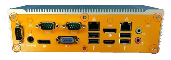
1. Remove the 6x Phillips screws from the rear of the unit as shown by the red circles below:

<figure><img src="https://3062424488-files.gitbook.io/~/files/v0/b/gitbook-x-prod.appspot.com/o/spaces%2FlLHqs7kbNoKOFTwGOfH6%2Fuploads%2Fgit-blob-ab852489bed3b5e63172503c3f6bdab518282c68%2Fb46fdba8da7c80a15cadbadc855887f58dc64e5f9590cad78993520a9e5d66cb.png?alt=media" alt="" height="192" width="547"><figcaption></figcaption></figure>

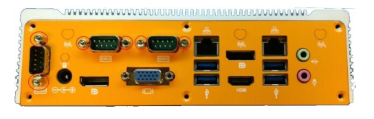
2. Remove the standoffs from the COM ports as shown below:

<figure><img src="https://3062424488-files.gitbook.io/~/files/v0/b/gitbook-x-prod.appspot.com/o/spaces%2FlLHqs7kbNoKOFTwGOfH6%2Fuploads%2Fgit-blob-933ddcc93e3470c3cf660872c59b1d26d8d7d2f6%2Fa411bdde095b45bac1b547e8af8a5b4d3321d8006b9bf87d464e56e90eb70020.png?alt=media" alt="" height="174" width="544"><figcaption></figcaption></figure>

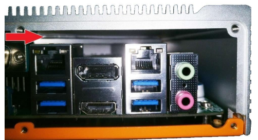
**Note the ridge between the heat block and the lid:**

<figure><img src="https://3062424488-files.gitbook.io/~/files/v0/b/gitbook-x-prod.appspot.com/o/spaces%2FlLHqs7kbNoKOFTwGOfH6%2Fuploads%2Fgit-blob-d886d757b027584c2262b9f3a941bd2a2638c968%2F393d415e39b8e7f9956def2a7a08405ae10c4ea501746c40255031515c4563b7.png?alt=media" alt="" height="272" width="502"><figcaption></figcaption></figure>

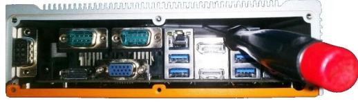
3. Insert a Flathead screwdriver into the ridge and pry the lid off by turning the screwdriver as shown below:

<figure><img src="https://3062424488-files.gitbook.io/~/files/v0/b/gitbook-x-prod.appspot.com/o/spaces%2FlLHqs7kbNoKOFTwGOfH6%2Fuploads%2Fgit-blob-1c33c909c09a61906f631f25042dfdadbf2fa701%2Fdb98eb9bbbe2207369ce143ce2b2536143ed650bac91f59281ff6be1dd9e56b7.png?alt=media" alt="" height="156" width="518"><figcaption></figcaption></figure>

4. Hinge off the lid at a 45 degree angle and remove it:

<figure><img src="https://3062424488-files.gitbook.io/~/files/v0/b/gitbook-x-prod.appspot.com/o/spaces%2FlLHqs7kbNoKOFTwGOfH6%2Fuploads%2Fgit-blob-6713d6fb5d0ca0db155666f060480bad00dfcb1d%2Fb02e61422c50c73b0f54b6b4403b98d466482f87ee48e3cbad23eae62483c772.png?alt=media" alt="" height="204" width="382"><figcaption></figcaption></figure>

**Model Specific Troubleshooting**

The following content outlines common service tasks performed on the ML400 and are broken out by model number. You can find your model number on the silver sticker located on the bottom of your unit.

## <mark style="color:blue;">ML400G-10</mark> <a href="#ml400g-10" id="ml400g-10"></a>

### Manual <a href="#product-manual" id="product-manual"></a>

<https://drive.google.com/open?id=1NgI4gRB-g1IZ9WPD-9p9znmZ-ZaaqKFB>

### Drivers <a href="#drivers" id="drivers"></a>

<https://drive.google.com/open?id=1XINF3lob4uC7xJRKcv8v62zuGiUzffV2>

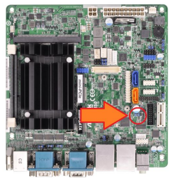
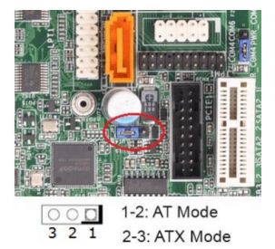
#### Enabling Auto Power On <a href="#how-to-enable-auto-power-on" id="how-to-enable-auto-power-on"></a>

1. Locate the AT/ATX jumper.
2. Move it over by 1 pin.
3. Auto power on is now enabled

<figure><img src="https://3062424488-files.gitbook.io/~/files/v0/b/gitbook-x-prod.appspot.com/o/spaces%2FlLHqs7kbNoKOFTwGOfH6%2Fuploads%2Fgit-blob-de374d57607f2b403e0420255de3f0867edafeac%2Fce39968840e29bd14862cfce285eae13d2a7b1201638cb463b8350578b70e4b3.png?alt=media" alt="" height="368" width="352"><figcaption><p>Locate the AT/ATX jumper.</p></figcaption></figure>

<figure><img src="https://3062424488-files.gitbook.io/~/files/v0/b/gitbook-x-prod.appspot.com/o/spaces%2FlLHqs7kbNoKOFTwGOfH6%2Fuploads%2Fgit-blob-1e31be326ce1f95034af60b5b4da93c6b0e2c793%2F2a1e05f73c52f397debc5fe4976b702689c0f24df7b704b2a81f138928ef0bf3.png?alt=media" alt="" height="275" width="303"><figcaption><p>Move it over by 1 pin, where pins 1-2 are AT Mode and 2-3 are ATX Mode.</p></figcaption></figure>

#### Clear CMOS <a href="#how-to-clear-cmos" id="how-to-clear-cmos"></a>

1. Locate the CLRMOS1 jumper.
2. Move the jumper over by 1 pin.
3. Wait 30 seconds.
4. Restore the jumper to its original position. The CMOS is now clear.

<figure><img src="https://3062424488-files.gitbook.io/~/files/v0/b/gitbook-x-prod.appspot.com/o/spaces%2FlLHqs7kbNoKOFTwGOfH6%2Fuploads%2Fgit-blob-192fe2cd219e9140f495782d0984a881406b6ccd%2F5f7b54d8a730cfdfc18340301220dc50add516544ae2891d5c4a244f423db689.png?alt=media" alt="" height="360" width="351"><figcaption><p>Locate the CLRMOS1 jumper.</p></figcaption></figure>

<figure><img src="https://3062424488-files.gitbook.io/~/files/v0/b/gitbook-x-prod.appspot.com/o/spaces%2FlLHqs7kbNoKOFTwGOfH6%2Fuploads%2Fgit-blob-b90a5a5adf0654d31fbc4e4bd8727e14110acbd8%2F5cf9cd4769c14b74769685132a4cd02bc3ff835cc760aa5b041a1fe40ee3a983.png?alt=media" alt="" height="266" width="230"><figcaption><p>Move the jumper over by 1 pin.</p></figcaption></figure>

## <mark style="color:blue;">ML400G-12</mark> <a href="#ml400g-12" id="ml400g-12"></a>

### Manual <a href="#drivers-2" id="drivers-2"></a>

<https://drive.google.com/open?id=1WUWKpPN7BcH42-Peib77aOSco6w_v_8q>

### Drivers

<https://drive.google.com/open?id=1UdA6mpn3c9VSSj3C2anhUeo702ifzd0c>

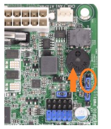
#### Enabling Auto Power On <a href="#how-to-enable-auto-power-on-2" id="how-to-enable-auto-power-on-2"></a>

1. Power on the unit and press the Del key repeatedly to access the BIOS.
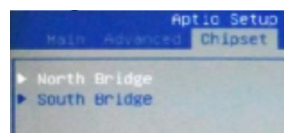
2. Navigate to the Chipset tab and open the South Bridge menu:

<figure><img src="https://3062424488-files.gitbook.io/~/files/v0/b/gitbook-x-prod.appspot.com/o/spaces%2FlLHqs7kbNoKOFTwGOfH6%2Fuploads%2Fgit-blob-3e9687f1e6a5e4cad1bc846ffbb121f8efdbef81%2Ff817c62315c83232bbf1b00246b80cce9868902a529f43c19ae6fbb4a31cdc33.png?alt=media" alt="" height="137" width="301"><figcaption></figcaption></figure>

3. Change System State after Power Failure to \[Always On].
4. Press Esc to go back.
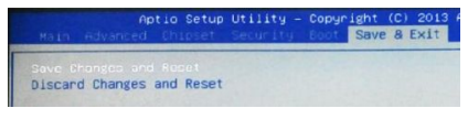
5. Save changes and reset from the Save & Exit tab:

<figure><img src="https://3062424488-files.gitbook.io/~/files/v0/b/gitbook-x-prod.appspot.com/o/spaces%2FlLHqs7kbNoKOFTwGOfH6%2Fuploads%2Fgit-blob-d2ff6dd802ea61912aa9148ede8da16447a8d0a5%2F82be7f176522782f7df415a84023648b571983ff41b809b9a6dbae0d3876b846.png?alt=media" alt="" height="108" width="424"><figcaption></figcaption></figure>

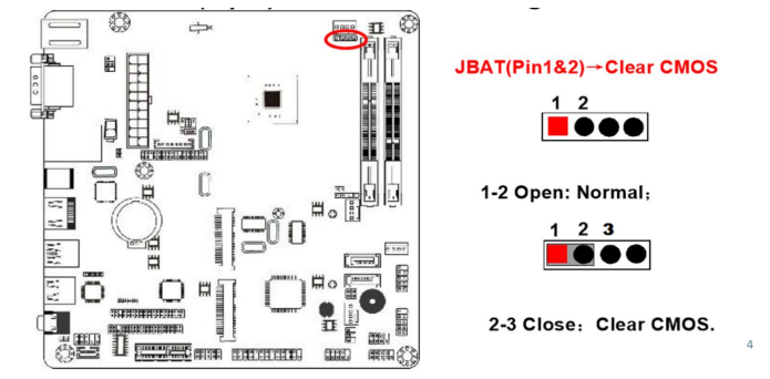
#### Clear CMOS <a href="#how-to-clear-cmos-2" id="how-to-clear-cmos-2"></a>

1. Locate the JBAT Jumper.
2. Short pins 1 and 2.
3. Wait 30 seconds.
4. Restore the jumper to its original position. The CMOS is now clear.

<figure><img src="https://3062424488-files.gitbook.io/~/files/v0/b/gitbook-x-prod.appspot.com/o/spaces%2FlLHqs7kbNoKOFTwGOfH6%2Fuploads%2Fgit-blob-5a38c921a65416d77bd498de7b79da29632247f8%2F194e7996e8559deb44eb6222c72b9f68abfe2d29398b71b90272dcc5636675a1.png?alt=media" alt="" height="342" width="695"><figcaption></figcaption></figure>

## <mark style="color:blue;">ML400G-30</mark> <a href="#ml400g-30" id="ml400g-30"></a>

### Manual <a href="#product-manual-3" id="product-manual-3"></a>

<https://drive.google.com/open?id=1LEZ4g-dhRQyQBrMyGhGayS90TVJMU-LC>

ASRock IMB-186 Motherboard

### Drivers <a href="#drivers-3" id="drivers-3"></a>

<https://drive.google.com/open?id=1RJPoD0gRRcAV-xkuIT6r_qmpW1V_BBh7>

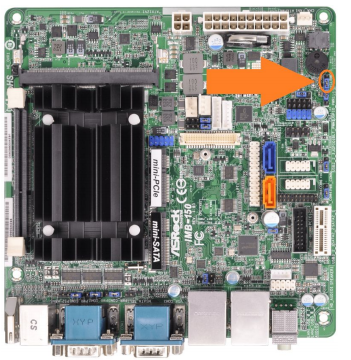
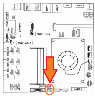
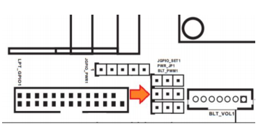
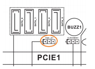
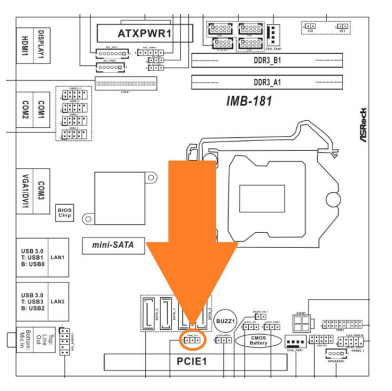
#### Enabling Auto Power On <a href="#how-to-enable-auto-power-on-3" id="how-to-enable-auto-power-on-3"></a>

1. Locate the PWR\_JP1 jumper indicated by the orange arrows

<figure><img src="https://3062424488-files.gitbook.io/~/files/v0/b/gitbook-x-prod.appspot.com/o/spaces%2FlLHqs7kbNoKOFTwGOfH6%2Fuploads%2Fgit-blob-ec2cfa64451bd6cca4f3254fbfb4601f23bf9525%2F2890db3f6aaeb0b952701bab005fa8b4a0e51d09ead793087fed241018cafc71.png?alt=media" alt="" height="407" width="405"><figcaption></figcaption></figure>

<figure><img src="https://3062424488-files.gitbook.io/~/files/v0/b/gitbook-x-prod.appspot.com/o/spaces%2FlLHqs7kbNoKOFTwGOfH6%2Fuploads%2Fgit-blob-bce290e5a45f0a4aa2c11e71b158ce3698bdcc7a%2F3f0b4633d1cd8f3777b6797597db70080705ad52e8d4a607886139bb226811fe.png?alt=media" alt="" height="189" width="380"><figcaption></figcaption></figure>

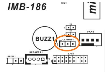
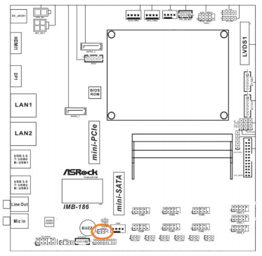
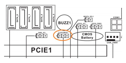
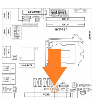
#### Clear CMOS <a href="#how-to-clear-cmos-3" id="how-to-clear-cmos-3"></a>

1. Locate the clear CMOS jumper.
2. Move the jumper over by 1 pin.
3. Wait 30 seconds.
4. Restore the jumper to its original position. The CMOS is now clear.

<figure><img src="https://3062424488-files.gitbook.io/~/files/v0/b/gitbook-x-prod.appspot.com/o/spaces%2FlLHqs7kbNoKOFTwGOfH6%2Fuploads%2Fgit-blob-edd39c74f56f74f95d676fc592d547e2bc2bf7ae%2Fe31ee6b2380d60aaf086ae20ea9842a03ff0adf9fffd42b3f85b3bbe6a84ded4.png?alt=media" alt="" height="272" width="377"><figcaption></figcaption></figure>

<figure><img src="https://3062424488-files.gitbook.io/~/files/v0/b/gitbook-x-prod.appspot.com/o/spaces%2FlLHqs7kbNoKOFTwGOfH6%2Fuploads%2Fgit-blob-3e502357034807887e959c9bf127f08cd25a169b%2F44b759fa2f6b662e7af8bd806f5439f8f635694939e339f0b1b5816c34cc8919.png?alt=media" alt="" height="365" width="373"><figcaption></figcaption></figure>

## <mark style="color:blue;">ML400G-51</mark> <a href="#ml400g-51" id="ml400g-51"></a>

### Manual <a href="#product-manual-4" id="product-manual-4"></a>

<https://drive.google.com/open?id=16rhOVroJDS1Ljop4OvjuuTtUvOK9tBPY>

### Drivers <a href="#drivers-4" id="drivers-4"></a>

<https://drive.google.com/open?id=1RI7U0gtxFDJszG4u98IqBHzVZWDxqriS>

#### Enabling Auto Power On <a href="#how-to-enable-auto-power-on-4" id="how-to-enable-auto-power-on-4"></a>

1. Locate the AT/ATX jumper.
2. Move it over by 1 pin.
3. Auto power on is now enabled.

<figure><img src="https://3062424488-files.gitbook.io/~/files/v0/b/gitbook-x-prod.appspot.com/o/spaces%2FlLHqs7kbNoKOFTwGOfH6%2Fuploads%2Fgit-blob-4e62f3608f7cab7e9ea8ee1ce724e3e7e35d39e9%2Fe453e319ad6f54ea4db800dc1ece45afa1179b3a24bd419e034d9db0c5f3378f.png?alt=media" alt="" height="227" width="313"><figcaption><p><br></p></figcaption></figure>

<figure><img src="https://3062424488-files.gitbook.io/~/files/v0/b/gitbook-x-prod.appspot.com/o/spaces%2FlLHqs7kbNoKOFTwGOfH6%2Fuploads%2Fgit-blob-87c413a4793620efc4ce2652b28822ac7bd8a6ae%2Fc9924d969c8f183888c878ed9bae30b01ba76db4d10c481336c8409a653d043f.png?alt=media" alt="" height="391" width="392"><figcaption></figcaption></figure>

#### Clear CMOS <a href="#how-to-clear-cmos-4" id="how-to-clear-cmos-4"></a>

1. Locate the CLRMOS1 jumper.
2. Move the jumper over by 1 pin.
3. Wait 30 seconds.
4. Restore the jumper to its original position. The CMOS is now clear.

<figure><img src="https://3062424488-files.gitbook.io/~/files/v0/b/gitbook-x-prod.appspot.com/o/spaces%2FlLHqs7kbNoKOFTwGOfH6%2Fuploads%2Fgit-blob-d0315bccb7a17d90c1e9b37bc47c7899b553c362%2Fb75ac28da3f1b0644d6f2198855ce7fe214ffcbaf94b70e30d8f1ae5620284d0.png?alt=media" alt="" height="218" width="433"><figcaption></figcaption></figure>

<figure><img src="https://3062424488-files.gitbook.io/~/files/v0/b/gitbook-x-prod.appspot.com/o/spaces%2FlLHqs7kbNoKOFTwGOfH6%2Fuploads%2Fgit-blob-95117607f303175bfddf737c12d16af93afb3ce4%2F336d6f81fafaa8bc199417af8be3cd708a610e9359a4e287649e7e24cbc66600.png?alt=media" alt="" height="349" width="332"><figcaption></figcaption></figure>

## <mark style="color:blue;">ML400G-52</mark> <a href="#ml400g-52" id="ml400g-52"></a>

### Manual <a href="#product-manual-5" id="product-manual-5"></a>

<https://drive.google.com/open?id=1Fxsvv12qMhNE8bIXRU1-cjcwNfCO3vAV>

Mitac PH12SI-I Motherboard

### Drivers <a href="#drivers-5" id="drivers-5"></a>

<https://drive.google.com/open?id=1h6whiW3LAtlNTqRVTpeoRP7ycZVy4Vxc>

#### Enabling Auto Power On <a href="#how-to-enable-auto-power-on-5" id="how-to-enable-auto-power-on-5"></a>

1. Power on the unit and press the Del key to access the BIOS
2. Navigate to the Chipset tab
3. Open the PCH-IO Config menu
4. Change”State After G3″ to S0
5. Save changes and exit
6. Auto power on is now enabled

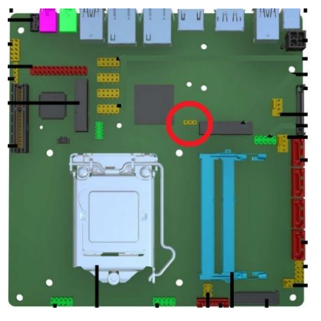
#### Clear CMOS <a href="#how-to-clear-cmos-5" id="how-to-clear-cmos-5"></a>

1. Locate the CLRMOS1 jumper
2. Move the
3. &#x20;jumper over by 1 pin
4. Wait 30 seconds
5. Restore the jumper to its original position
6. The CMOS is now clear

<figure><img src="https://3062424488-files.gitbook.io/~/files/v0/b/gitbook-x-prod.appspot.com/o/spaces%2FlLHqs7kbNoKOFTwGOfH6%2Fuploads%2Fgit-blob-57d540844a3a1f3f54aa8746e0aa83b9caaf1051%2F4303af9cb40d107869c3e2f08ac0ae94a67e043ad2203441f8f6240774690ff4.png?alt=media" alt="" height="457" width="456"><figcaption></figcaption></figure>

## <mark style="color:blue;">Security Advisory</mark>

For the latest security advisories concerning OnLogic products, including vulnerability disclosures and necessary updates, please refer to our official Security Advisories page. It is recommended to regularly check this resource for critical security information.\
[**Access Security Advisories**](/support-articles/security-advisories.md)