Connector Type
Due to the wide variety of potential applications, OnLogic does not supply a mating connector. Below is an example list of connectors compatible with this module.
https://www.digikey.com/en/products/detail/w%C3%BCrth-elektronik/61201623021/2060599
https://www.mouser.com/ProductDetail/Wurth-Elektronik/61201623021?qs=ZtY9WdtwX57DLOr1z4RBOw%3D%3D
Features
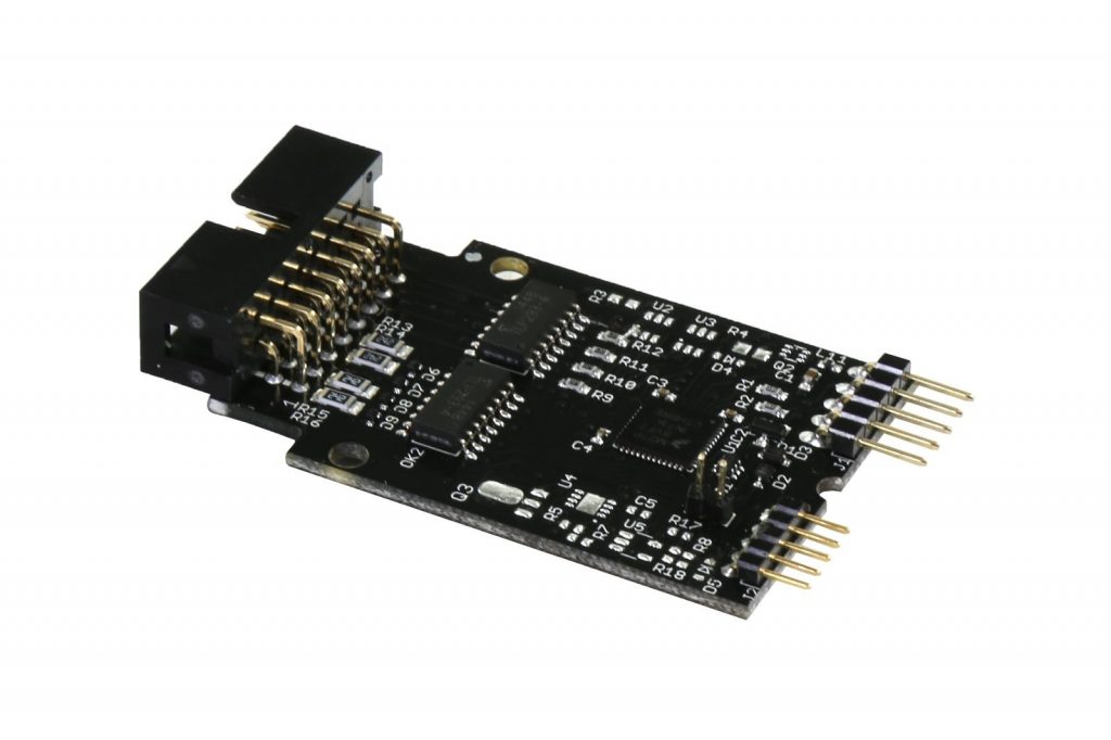
- Isolated Digital Input/Output
- Four Inputs, 0-16V (2.5V HIGH), dry contact
- Four Outputs, 50mA, open collector
- Keyed 2.54mm connector
- IO Isolation to 3750 Volts (*Rated, not tested)
- Simple-to-program USB-serial interface
- Onboard ARM Cortex-M0 processor
- Latches and 32-bit counters for inputs
Connections & Wiring
DIO Header (externally facing)
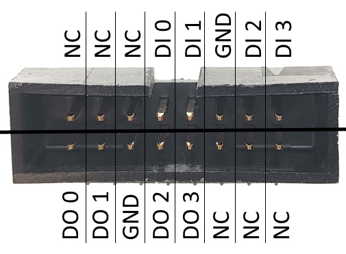
The header is 2×8 pins, 2.54mm pitch, with shroud and key
For mating connector, use Wurth Electronics 61201623021 or similar.
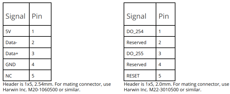
USB J1 (Left) MISC J2 (Right)
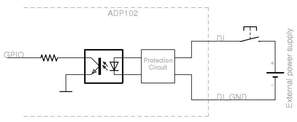
Sample Input Circuit
Digital inputs are triggered by the flow of a small amount (1-2mA) of current through DI. Current is limited, and correct polarity is ensured by the ADP102’s built-in protection circuit. A request for DI state will report active when the voltage at DI exceeds 2.5 V.
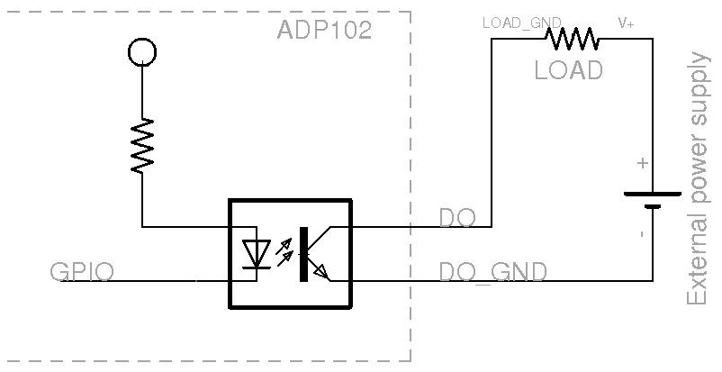
Sample Output Circuit
Digital outputs switch a circuit in series after the device they control (represented by LOAD). Each output is rated for 50mA. If more than 50mA are required, DO may be used to trigger a relay driving LOAD instead.
Application Interface
The ADP102 provides a standard USB-CDC (USB-serial) interface. To determine the COM port number, check device manager or equivalent for the COM device. A developer may employ any serial-compatible software library in order to communicate with the ADP102. Available commands are outlined below. After the execution of any command, a response is returned by the ADP102 containing any requested data. For commands that do not return a value, a success/failure code is returned instead.
Command Structure
Each command is comprised of a start character, length (not including the start character), 1-byte pin address, 2-byte command ID, and (optional) data. For example, to set the state of digital output 3 to ‘ON’, the command packet is:
| Start | Length | Address | Command High | Command Low | Data |
| 0x24 | 0x05 | 0x03 | 0x01 | 0x02 | 0xFF |
Digital Output Commands
| Name | Command | Value | Description |
| Get State | 0x0101 | Address | Get the IO pin input state. Returns the status of output pins as well. |
| Get Latch State | 0x0102 | Address | Get the input pin latch bit state. |
| Get Count | 0x0103 | Address | Get the input pin counter value. This counter is incremented at every low-to-high or high-to-low state change, depending on configuration. |
| Clear Count | 0x0104 | Address | Return the input counter value, then reset it to zero. |
| Set State | 0x0108 | Address, State | Set an output pin to the specified state. 0x00 species LOW, all others evaluate to HIGH. |
| Toggle State | 0x0109 | Address | Toggle an output pin to the opposite state. |
| Get Model Number | 0x0001 | None | Return the device model number. |
| Get Configuration | 0x0004 | Address | Return the configuration of the specified pin. |
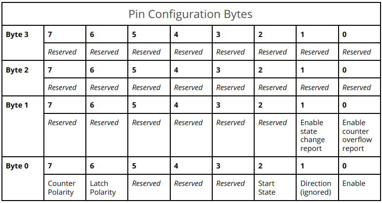
| Set Configuration | 0x0005 | Address, Configuration | Set the configuration of the specified pin. Available configuration settings are described in the section below. Unless this is followed by “Save Configuration” this is not preserved across reboots. |
| Save Configuration | 0x0006 | 0x00 | Save all pin configurations as “boot” settings. 0x00 must be provided in the data field. |
Response Structure
After executing each command, the ADP102 issues a response containing data the command generated (if any) and a success code. The first two bytes of a response packet are the incoming command code that generated the response OR’d with 0x8000, followed by the pin number requested and any relevant data. The packet is completed by the same carriage return delimiter as the command packet.
For example, a response to the ‘Get input status’ command looks like this:
| Start Byte | Length | Address | Command High | Command Low | Data | End |
| 0x24 | 0x04 | 0x00 | 0x82 | 0x02 | 0xFF | 0x13 |
State Change Reports
The ADP102 may also be configured to send a report to the host system whenever an input changes state, or a counter overflows (reaches the maximum value of 2^32 and resets). These reports are formatted as responses to the input “Get State” command (0x8101 [Address] [State] 0x13). They may be enabled or disabled via their respective configuration bits in each pin’s configuration.
Sample Code (Python)
''' Example usage of the ADP102 DIO expansion card '''

import sys
from time import sleep
import functools

from serial import Serial  # python -m pip install pyserial

# Detecting serial port
import serial.tools.list_ports as system_ports


def get_device_port() -> str:
    ''' Scans system to detect device CDC ACM port '''

    all_ports = system_ports.comports()

    for port, _, hwid in sorted(all_ports):
        if "15A2:0300" in hwid:
            # Replace with "1FC9:0094" if using ADP120
            # Fix for windows COM ports above 10
            if 'win' in sys.platform:
                return "\\\\.\\" + port
            else:
                return port

    return None


class PinConfig:
    ''' Pin configuration; used to set or report a pin config

    PARAMETERS:
        state_change:            Report to host when pin state has changed
        counter_overflow:        Report to host when pin counter has overflown
        counter_polarity:
        latch_polarity:
        starting_state:          Initial pin state
        enable:                  Enable/disable pin

    '''

    def __init__(self, state_change=False, counter_overflow=False, counter_polarity=0, latch_polarity=0,
                 starting_state=0, enabled=True):
        self.state_change = state_change
        self.counter_overflow = counter_overflow
        self.counter_polarity = counter_polarity
        self.latch_polarity = latch_polarity
        self.starting_state = starting_state
        self.enabled = enabled

    def bytes(self):
        nbytes = [0x00, 0x00, 0x00, 0x00]

        if self.state_change:
            nbytes[2] |= 0x02

        if self.counter_overflow:
            nbytes[2] |= 0x01

        if self.enabled:
            nbytes[3] |= 0x01

        if self.starting_state:
            nbytes[3] |= 0x04

        if self.latch_polarity:
            nbytes[3] |= 0x40

        if self.counter_polarity:
            nbytes[3] |= 0x80

        return bytes(nbytes)

    @staticmethod
    def from_bytes(nbytes):
        nbytes = list(nbytes)

        config = {
            'state_change': True if nbytes[2] & 0x02 else False,
            'counter_overflow': True if nbytes[2] & 0x01 else False,
            'enabled': True if nbytes[3] & 0x01 else False,
            'starting_state': True if nbytes[3] & 0x04 else False,
            'latch_polarity': True if nbytes[3] & 0x40 else False,
            'counter_polarity': True if nbytes[3] & 0x80 else False,
        }

        return PinConfig(**config)


class ADP102(Serial):
    ''' Subclass serial with ADP102 specific commands '''

    START = b'\x24'
    END = b'\x00\x80\x01'
    COMMANDS = {
        'model': b'\x00\x00\x01',
        'serial': b'\x00\x00\x03',
        'read_state': b'\x01\x01',
        'read_latch': b'\x01\x02',
        'read_count': b'\x01\x03',
        'clear_latch': b'\x01\x04',
        'clear_count': b'\x01\x05',
        'toggle_output': b'\x01\x09',
        'save_config': b'\x00\x06',
    }

    def __init__(self, *args, **kwargs):
        ''' Initialize serial device; set port timeout if missing '''
        if 'timeout' not in kwargs:
            kwargs['timeout'] = 5
        if 'write_timeout' not in kwargs:
            kwargs['write_timeout'] = 0

        super(ADP102, self).__init__(*args, **kwargs)

    def command(self, cmd: bytes, adr=None) -> bytes:
        ''' Send and ADP102.COMMAND to the hardware device '''
        if adr is None:
            return self.write_command_raw(cmd)
        else:
            return self.write_command_raw(bytes([adr]) + cmd)

    def read_response(self) -> bytes:
        ''' Read the response to a command '''
        r = self.read(1)
        if r == self.START:
            rlen = self.read(1)
            return self.read(ord(rlen) - 1)[3:]
        else:
            sleep(0.01)
            return self.read(self.in_waiting)

    def write_command_raw(self, cmd: bytes) -> bytes:
        ''' Write the raw bytes to the serial device '''
        # Raw command
        raw = self.START + bytes([len(cmd) + 1]) + cmd

        # Write the command
        count = self.write(raw)

        # Check whole command was written
        if count != len(raw):
            return None

        # Get the response
        reply = self.read_response()

        return reply

    def write_config(self, address, config):
        ''' Configure a pin '''
        return self.write_command_raw(bytes([address]) + b'\x00\x05' + config.bytes())

    def read_config(self, address):
        config = self.write_command_raw(bytes([address]) + b'\x00\x04')

        return PinConfig.from_bytes(config)

    def write_output(self, address, state):
        return self.write_command_raw(bytes([address]) + b'\x01\x08' + bytes([state]))

    # Support ADP102.model() syntax
    def __getattr__(self, name):
        cmd = self.COMMANDS.get(name)

        if cmd is None:
            raise AttributeError(name)
        else:
            result = functools.partial(self.command, cmd)

        return result


if __name__ == "__main__":
    port_name = get_device_port()

    # Detect the ADP102 module
    if port_name is None:
        print("Failed to detect device!")
        sys.exit(-1)

    adp = ADP102(port_name)

    # Report model and firmware version
    print(f"Model: {adp.model()}")

    # Read input and output states
    for i in range(0, 8):
        print(f"{'Input' if i < 4 else 'Output'} {i if i < 4 else i - 4} State: {adp.read_state(i)}")

    # Read the config of output 0
    cfg = adp.read_config(4)
    print(f"Output 0:\n  Starting state: {cfg.starting_state}\n  Enabled: {cfg.enabled}")

    # Toggle the starting state, and enable the port
    cfg.starting_state = False if cfg.starting_state else True
    cfg.enabled = True
    adp.write_config(4, cfg)

    cfg = adp.read_config(4)
    print(f"Output 0:\n  Starting state: {cfg.starting_state}\n  Enabled: {cfg.enabled}")

    # Write an output and confirm it worked
    adp.write_output(4, 1)
    print(f"Current State: {adp.read_state(4)}")