An optional DIO add-in card is available. The add-in card has an NXP i.MX1050-series microcontroller that can communicate with the host processor over USB. The card provides an interactive shell for configuration on a virtual COM port.
Supported VIN/Input/Output Voltage: 5-48V
Configuring the DIO Card
The add-in card is configured interactively through its shell using a serial terminal emulator program. The shell is accessed differently depending on operating system.
To access the shell on Windows:
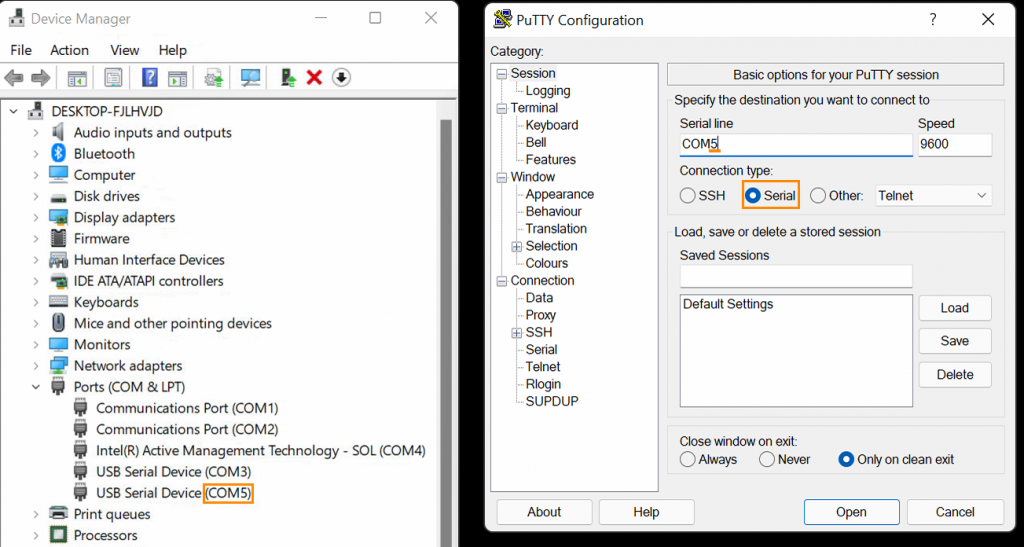
- Open Device Manager by pressing Win+X M. Open the “Ports (COM & LPT)” menu.
- Note the “COM#” numbers on each port listed.
- Download and install PuTTY from the link above.
- Open PuTTY. When prompted, enter the COM port number in the “Serial line” text box, then click “Open”.
- If the port number was correct, a “uart:~$” prompt should appear. If not, try a different port.
To access the shell on Linux:
- Install picocom, e.g. “sudo apt install picocom” on Ubuntu.
- Open the shell’s virtual COM port with picocom by running “picocom /dev/serial/by-id/usb-OnLogic_DIO-*-if00”.
- Some Linux distributions may not configure udev to produce by-id links. If those links are missing, try /dev/ttyACM0 and similar devices.
Once the shell is open, type “help” for usage information. A description of available shell commands can also be found here.
While the microcontroller shell is intended for human interaction, it can be used to programmatically control the MCU. To avoid a number of pitfalls when doing so, observe the following best practices:
- On Linux, use the symlinked device nodes inside
/dev/serial/by-idinstead of hardcoding/dev/ttyACMxdevice names./dev/ttyACMxnumbering is - unstable;
/dev/serial/by-id/usb-OnLogic_<device>-if00will reliably point to the terminal interface. - When writing Linux shell scripts, ensure that the echo flag is disabled on the TTY by running
stty -F /dev/serial/by-id/<device> -echobefore - interacting with the shell. Most serial libraries (pyserial, serialport-rs, etc.) will automatically disable this flag.
- When sending a command, precede it with a ‘\x03’ byte to clear the terminal’s line buffer and ensure that the command is interpreted correctly. Follow the command with a ‘\r’ or ‘\n’ character to execute the command.
- Send less than 64 bytes at a time. To send longer commands, explicitly flush the port’s output buffer in between each block of 64 bytes.
Connection Diagrams
 | Pin | Function |
| 1 | DI 3 | |
| 2 | VISO | |
| 3 | DI 2 | |
| 4 | NC | |
| 5 | DI 1 | |
| 6 | NC | |
| 7 | DI 0 | |
| 8 | NC | |
| 9 | DO 3 | |
| 10 | GND | |
| 11 | DO 2 | |
| 12 | GND | |
| 13 | DO 1 | |
| 14 | GND | |
| 15 | DO 0 | |
| 16 | GND |
Digital Input (Active-Low)

Digital Input (Active-High)

Digital Output (Low-Side/Sinking)
