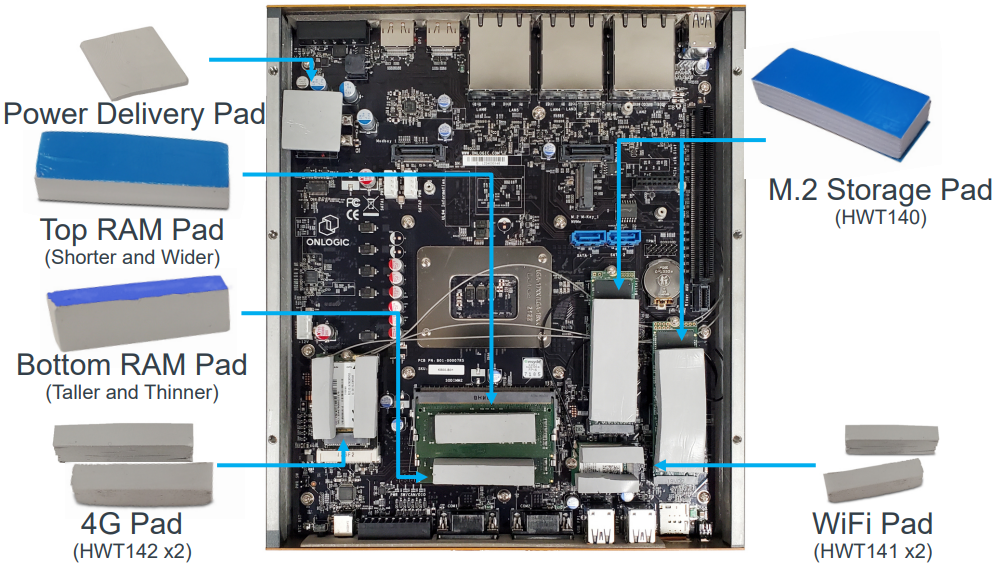
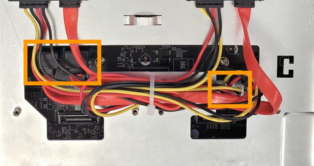
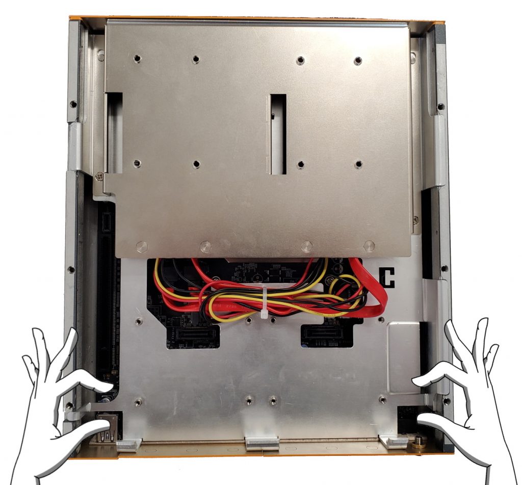
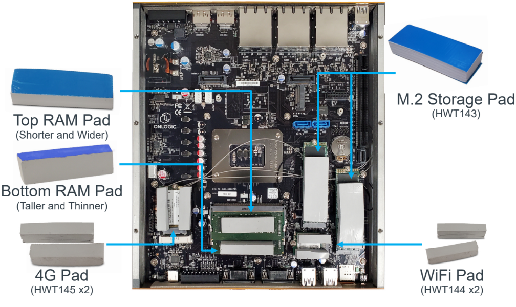
# Industrial Products
# CL100 Series
# CL100G
This page also applies to the TM700 ThinManager Ready platform.
## Technical Resources
*This article also applies to the TM700*.
### Downloads
Technical information related to the system's motherboard can be found from the support link below.
{% embed url="" %}
#### Drivers
The drivers for this ASRock motherboard are no longer hosted on their website, but you can download them from these links individually:
**VGA driver -**
**NUC TXE Driver** -
Additionally, you can reach out to ASRock customer support directly to see if they can provide additional assistance for the N3160-NUC-IPC motherboard, which is installed in this system:
#### CL100G CAD Files
{% file src="/files/P3d1FQW33kMZtsRc6mHO" %}
### Auto Power On
The CL100 can be configured to turn on automatically when DC power is connected. This is useful for power outage recovery or if the unit is mounted in a hard to reach location. You can enable Auto Power On by following the steps listed below.
* Power on the unit and immediately press the F2 key until you see the BIOS screen
* Using the arrow keys, navigate to the Advanced tab and enter the Chipset Configuration menu
* Next, locate the Restore on AC/Power Loss option
* Change it to \[Power On]
* Finally, navigate to the Exit tab and choose the Save Changes and Exit option
* The system will reboot and is now configured for auto power on
### Internal Access
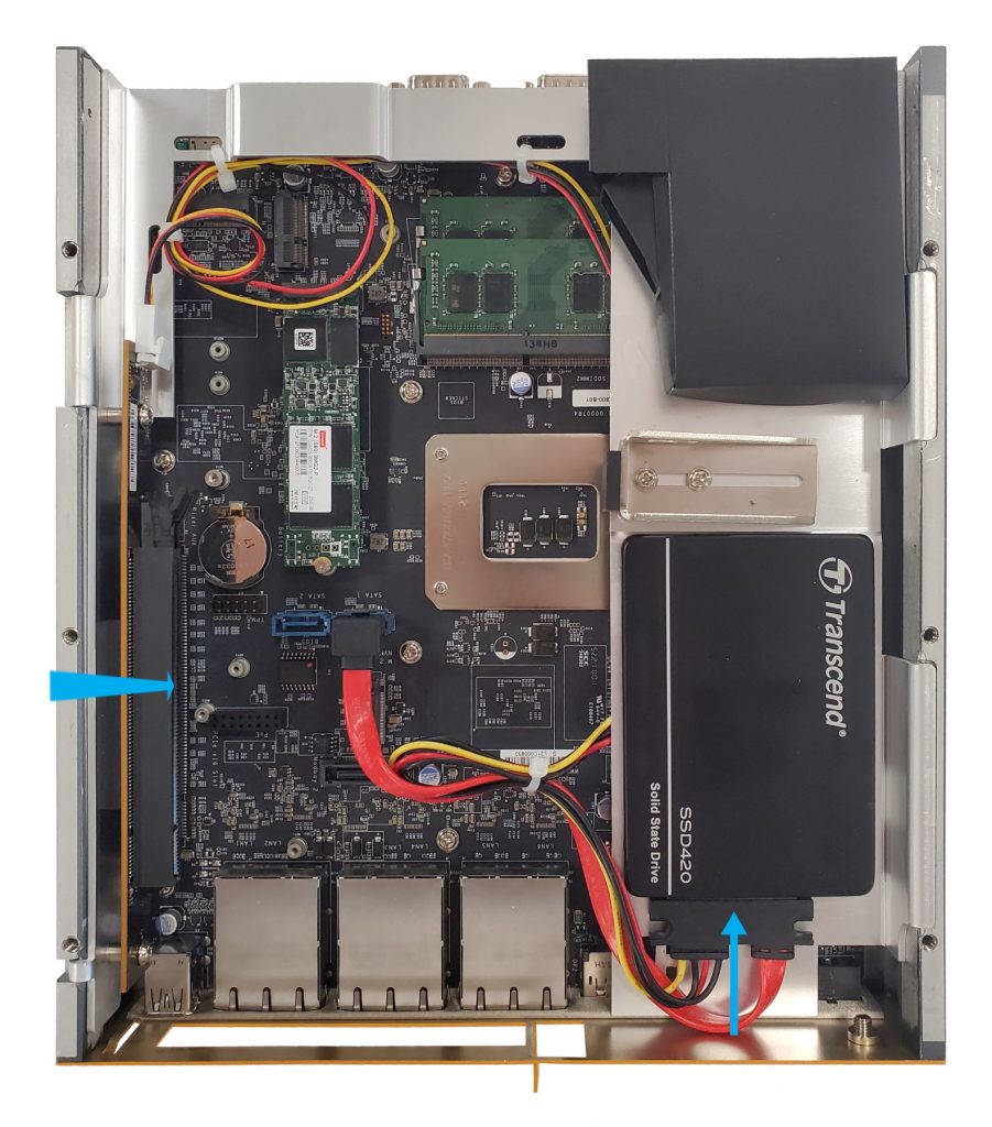
Opening the CL100 does not void the manufacturer’s warranty. However, some precautions are necessary to avoid damaging the unit.
* Perform this disassembly in an area free of static discharge
* Before beginning, touch a grounded metal surface to discharge your body of static electricity
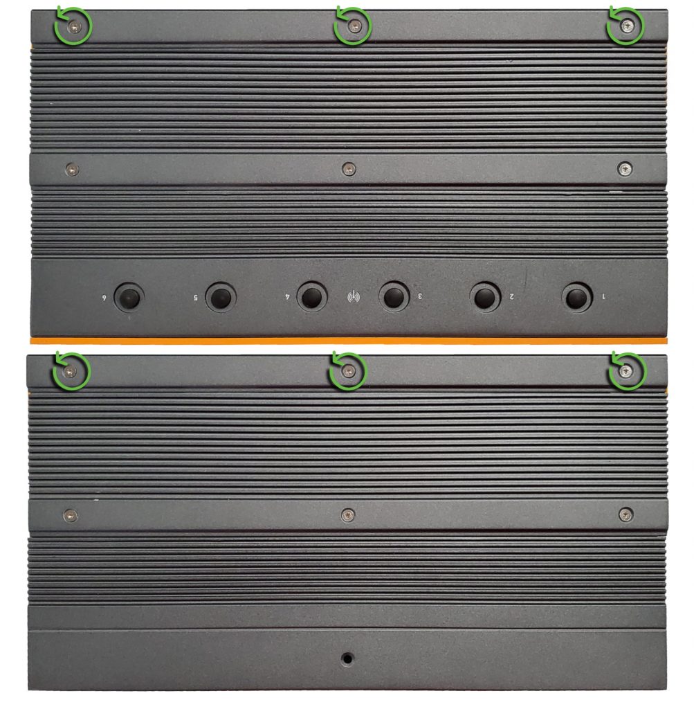
#### Opening the CL100 case
* Unplug the system and turn it upside down
* If applied, remove the rubber feet to access the screws
* Next, use a small P1 Phillips driver to remove the screws
* Now the bottom plate can now be removed. There may be slight resistance from the sticky thermal pad found inside
### Clear CMOS
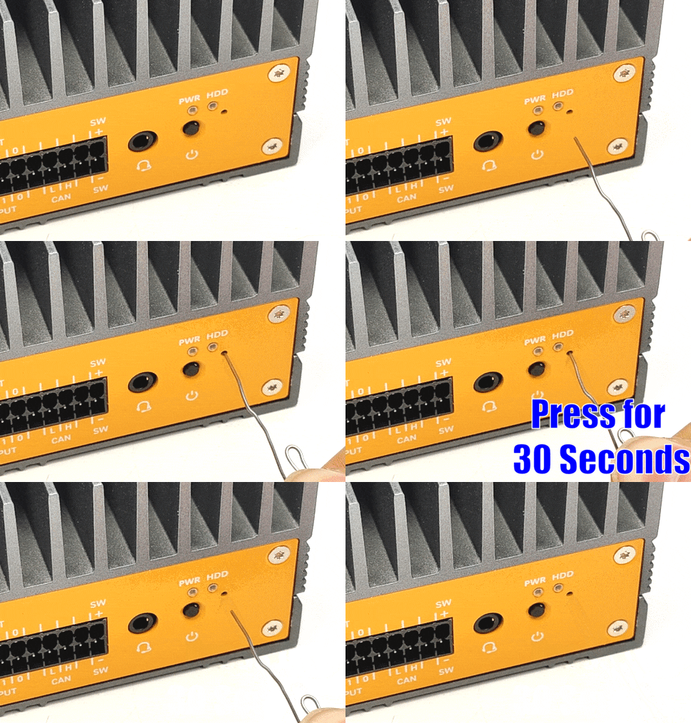
* First, locate the clear CMOS pad (circled in red)
* Then use a flathead screwdriver or other piece of metal to short the two halves together for 30 seconds
* After that, reinstall the bottom plate and power on the CL100. If it fails to function at this point, you may need to send it in for repair. If this is the case, please contact our Technical Support Team.
### mSATA storage
#### Installation
* Unplug the system and turn it upside down
* If applied, remove the rubber feet to access the screws
* Next, use a small P1 Phillips driver to remove the screws
* Now the bottom plate can now be removed. There may be slight resistance from the sticky thermal pad found inside
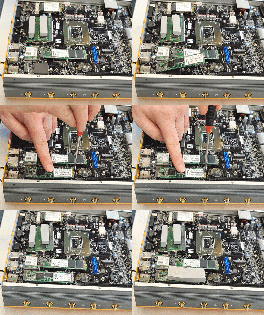
* Watch the animation to the right:
* Insert the mSATA drive into the slot
* Secure with M2 screw
* Peel and apply thermal pad
* Reinstall bottom plate
#### Removal
If your mSATA storage drive is not detected or you want to replace it, you can remove it by following the steps below.
* First, remove the small Phillips screw holding the drive in place. The drive will pop up to a 45-degree angle
* Next, pull the drive straight out and away from the slot
* Then, reinsert the drive and re-install the screw
### UEFI/Legacy Boot Mode
* Power on the CL100 and immediately press the F2 key until you see the BIOS screen
* Navigate to the Boot tab
* Open the CSM submenu
* Enable CSM for legacy boot mode, disable CSM for UEFI boot mode
* Press F10 to Save and Exit
## Security Advisory
For the latest security advisories concerning OnLogic products, including vulnerability disclosures and necessary updates, please refer to our official Security Advisories page. It is recommended to regularly check this resource for critical security information.\
[**Access Security Advisories**](/support-articles/security-advisories)
# CL200 Series
This page also applies to the TM110, TM710, and TM720 ThinManager Ready platforms.
# CL250 / CL210 / CL200
CL2X0 Series
## 1- Product Overview
Ultra-small form factor computers that are designed to be reliable and feature-rich, with a fanless and ventless design for durability and effective cooling. The CL200 series are IoT-ready with configurable options for 4G LTE, Wi-Fi/Bluetooth, and advanced functionalities like Movidius and multi-CEC. Measuring just 34 mm x 115 mm x 82 mm, the CL200 can be installed in compact spaces while maintaining connectivity.
### 1.1- Box Contents & Accessories
CL200 Assembly
CL210 & CL250 Assembly
**Accessories**
* Power Adapter
* Thermal Pads
Thermal Pads are used to assist with cooling expansion mSATA and mPCIe cards. If you purchased your system with expansion cards pre-installed, the thermal pads will already be installed inside the system. If you purchased additional items such as mounting brackets, power supplies, or antennas, they will be located in the system box or within the outer shipping carton.
### 1.2- System Specifications
Feature
CL200 (Standard-Basic)
CL210 (Standard-Advanced)
CL250
Form Factor
Pico ITX (100mm x 72mm)
Pico ITX (100mm x 72mm)
Pico ITX (100mm x 72mm)
Processor
Intel® Celeron® N3350
Intel® Celeron® N3350
Intel® Celeron® J3455
System Memory
2GB LPDDR4 onboard
4GB LPDDR4 onboard
8GB LPDDR4 onboard
Graphics
Intel® HD Graphics 500
Intel® HD Graphics 500
Intel® HD Graphics 500
Audio
Realtek ALC233
Realtek ALC233
Realtek ALC233
Super I/O
Nuvoton NCT 5524
Nuvoton NCT 5524
Nuvoton NCT 5524
LAN (1 & 2)
Realtek RTL8111H
Realtek RTL8111H
Realtek RTL8111H
Expansion 1
Full-length mPCIe slot (PCIe/USB/mSATA signal)
Full-length mPCIe slot (PCIe/USB/mSATA signal)
Full-length mPCIe slot (PCIe/USB/mSATA signal)
Expansion 2
Half-length mPCIe slot (PCIe/USB signal)
Half-length mPCIe slot (PCIe/USB signal)
Half-length mPCIe slot (PCIe/USB signal)
WiFi Antenna
4 x Antenna holes
4 x Antenna holes
4 x Antenna holes
Onboard Storage
8GB eMMC
32GB eMMC
None
Rear I/O
Micro SD slot
Micro SD slot
Micro SD slot
Front I/O: Audio
Jack (Mic-in/Line-out)
Jack (Mic-in/Line-out)
Jack (Mic-in/Line-out)
Front I/O: mDP
1 x mini-Display Port
2 x mini-Display Port
2 x mini-Display Port
Front I/O: LAN
1 x Gb LAN port
2 x Gb LAN port
2 x Gb LAN port
Front I/O: USB
2 x USB 3.0
2 x USB 3.0
2 x USB 3.0
Bottom I/O
1 x Power button 1 x LED (on the backside of PCB) 1 x USB2.0 vertical type 1 x 12V DC-in barrel RS 232 Box Header Connector
1 x Power button 1 x LED (on the backside of PCB) 1 x USB2.0 vertical type 1 x 12V DC-in barrel RS 232 Box Header Connector
1 x Power button 1 x LED (on the backside of PCB) 1 x USB2.0 vertical type 1 x 12V DC-in barrel RS 232 Box Header Connector
Onboard Headers and Connectors
1 x RTC battery header 1 x CEC header (module population is optional) 1 x clear CMOS, AT/ATX Jumper
1 x RTC battery header 1 x CEC header (module population is optional) 1 x clear CMOS, AT/ATX Jumper
1 x RTC battery header 1 x CEC header (module population is optional) 1 x clear CMOS, AT/ATX Jumper
miniDisplay Port connector - J54-DDI0 1st display miniDisplay Port connector - J55-DDI1 2nd display (optional)
A3
RJ45 LAN connector - J_Lan_1 RJ45 LAN connector - J_Lan_2 (optional)
A4
Dual USB3.0 connector
A5
Power Button
A6
Battery Header
A7
HDMI CEC Header (Optional)
A8
RS-232 COM Box Header
A9
Clear CMOS + AT/ATX Mode Header
A10
USB2.0 Verticle Type Connector
A11
DC-IN Power Jack
A12
Half-Height mPCIE Slot
A13
mPCIE Slot/mSATA Slot
Item
Functional Description
B1
Micro SD Connector
#### Memory & Storage
Memory and storage are soldered on the motherboard for the CL200 Series computers. Memory for both systems are LPDDR4 dual channel RAM. Both systems use industrial-grade eMMC onboard storage. Manufacturers and part numbers are subject to change, so please check the system pages for updates. Additional storage is available using the uSD card Revision 3.01 (SDXC) supporting up to 2TB.
| System | Storage | Manufacturer | Part Number | Size |
| --------- | ------- | ------------ | -------------- | ----- |
| CL200G-10 | eMMC | San Disk | SD1NBDG4-8G | 8 GB |
| CL210G-10 | eMMC | Samsung | KLMG2JETD-B041 | 32 GB |
| System | Memory | Manufacturer | Part Number | Size |
| --------- | ------ | ------------ | --------------- | -------- |
| CL200G-10 | LPDDR4 | Samsung | K4F8E304HB-MGCH | 1 GB x 2 |
| CL210G-10 | LPDDR4 | Samsung | K4F6E304HB-MGCJ | 2 GB x 2 |
#### Combo Audio Jack
The audio jack is implemented using the Realtek ALC233-VB2 and supports Nokia and Apple headset connectors.
CL200 Series Combo Audio Jack
| Pin | Nokia Headset Connector | Standard Connector |
| --- | ----------------------- | ------------------ |
| 1 | Left | Left |
| 2 | Right | Right |
| 3 | Mic | Ground |
| 4 | Ground | Mic |
#### LAN Port
#### Serial Port
The serial port header is 2x5, 2.54 mm pitch, colored black and keyed at pin 10.
#### Mini-PCI Express Expansion Slots
Standard pin-out supports half-height PCIe/USB and full-height PCIe/USB/mSATA signal.
### 2.3- Jumpers and Headers
**Jumper Set Up**
The following illustration shows how to use jumpers.
“Short” pins together by placing the jumper shunt on pins. Pins not capped with jumpers are “open”. With the illustrated 3-pin jumper, the shunt shorts pins 1 and 2. Check the corresponding header pin attributes to see what functionality is supported by shorting different pin pairs.
#### **AT/ATX, CMOS Jumper**
The following illustration shows the header without any jumpers.
This illustration shows jumpers in the default 6-4 and 5-3 positions.
| Function | Setting |
| ------------------ | ------- |
| Clear CMOS | 2-4 |
| Normal (default) | 4-6 |
| AT Mode | 1-3 |
| ATX Mode (default) | 3-5 |
**Clearing the CMOS**
Setting the jumper with the Clear CMOS jumper shunt allows you to clear the data in the CMOS. **NOTE:** Do not clear the CMOS right after updating the BIOS. You must boot up the system first and then shut it down before clearing the CMOS. **NOTE:** The password, date, time user default profile will be cleared only if the CMOS battery is removed.
To clear and reset system parameters to the default setup, follow these steps:
1. Turn off the computer and unplug the power cord from the power supply.
2. Wait 15 seconds.
3. Remove the jumper shunt from pins 6 and 4 and use it to short pins 2 and 4 on the header for 5 seconds.
4. Remove the jumper shunt and return it to short pins 6 and 4.
#### 2-Pin Battery Cable Header
The 3V Battery coin cell cable header is clearly labeled:
Function
Setting
3V Power
Pin 1
GND
Pin 2
#### HDMI CEC Header
If it was selected and configured in the build, the chip will be populated. CEC functionality will work with an HDMI adapter. Please see series pages for additional information.
### 2.4- Processor
#### Processor Core Design
#### Processor Graphics
Onboard Intel HD Graphics 500 processing circuitry is integrated into the processor. Single Display supports a maximum resolution of up to 3840x2160 (4K) @ 60 Hz. Dual independent displays are achieved through the optional second Mini-Display Port. Up to three mirrored displays are achieved via Display Port v1.2 daisy chaining.
### 2.5- Power Management
The CL200 Series supports multiple power states. These states can be configured on the motherboard. This section describes the power management functions you can perform.
#### Unexpected Shutdown Function
An unexpected shutdown does not necessarily cause a loss of data, but it can make access to some of your data difficult. To remedy this possibility, follow this procedure to power up the system again after the system power has been off for more than 4 seconds:
* If the SOC BIOS mode is set to AT mode, press the Power button once to power on the system.
* If the SOC BIOS mode is set to ATX mode, press the Power button twice to power on the system.
#### Wake-Up Events
The motherboard supports the following wake-up events.
| Wake-Up Event | From ACPI State | Comments |
| ------------- | --------------- | ------------------------------------------ |
| Power Button | S3, S4, S5 | |
| RTC Alarm | S3, S4, S5 | monitor to remain in sleep state |
| LAN | S3, S4, S5 | |
| USB | S3 | |
| PCIe | S3, S4, S5 | via WAKE; monitor to remain in sleep state |
Notes: S4 implies OS support only. USB ports must be turned off during S4/S5 states.
## 3- Installation & Mechanical
### 3.1- Dimensions
### 3.2- Mounting
#### Clip Installation & Wall Mounting
1. **Step 1:** Mark and prep holes in surface for mounting.
2. **Step 2:** Attach wall mount brackets to chassis.
3. **Step 3:** Fasten system to surface.
CL200 Mounting Plate Side
CL200 Mounting Plate Back
#### DIN Rail Mounting
1. **Step 1:** Attach DIN Rail mounting brackets to the chassis.
2. **Step 2:** Clip system to the DIN Rail.
### 3.3- Internal Access
#### Pre-Installation Precautions
It is important to read the following precautions before installing expansion cards into the motherboard:
* Wear a grounding strap attached to a grounded device to avoid damage from static electricity.
* Before opening the system, discharge static electricity by touching the metal case to a grounded object.
* Leave components in the static-proof bags they came in until they can be installed.
* Hold all circuit boards by the edges.
* Do not bend circuit boards.
#### **Internal Access**
* Remove the two silver Phillips screws
* Use a flathead screwdriver or similar tool to gently lever the bottom cover off
#### Reassembly
* Hinge the bottom plate back onto the system by aligning the tabs
* Reinstall the silver Phillips screws
#### Building CL200 Series with Wi-Fi
To add Wi-Fi to the CL200 Series, follow this procedure.
1. Before starting, ensure that you have read and understand the installation precautions listed above in the "Pre-Installation Precautions" section. \\
2. Remove both screws from the front of the case. Retain screws. \\
3. Remove the cover of the unit by sliding it toward the rear. \\
4. Remove rubber port blockers to install SMA connector through antenna holes. Remove nut first and line up the key. Install nut on the outside to hold connector in place. \\
5. Unscrew the screw on the standoff for the card length required. Retain screw. \\
6. Insert card at a 45 degree angle into the mPCIe slot until it snaps in. \\
7. Press down on the card's edge and screw down using retained screw into standoff. \\
8. Install second card as needed following the same instructions as above. \\
9. If installing broadcast modules, install MHF4 pigtail cable to the module. Make sure the MHF4 cable maps to the correct port. \\
10. Remove clear sticker backing from thermal pads to attach to installed modules. \\
11. Install thermal pads onto installed modules, making sure to keep all wires free from pads and other ports.
12. Install cover onto the unit using retained screws. \\
13. Install antennas to exposed SMA connector. \\
### 3.4- CAD & Drawings
{% file src="/files/7HSIQzo2gSekxNYqn8tN" %}
## 4- Software & Firmware
### 4.1- BIOS
#### UEFI Overview
The following section describes the CL200 Series UEFI. It shows each screen menu with a table describing the various fields and values.
#### Main Page
#### Advanced Page
**SMART Settings**
**NCT5524D Super IO Configuration**
**Hardware Monitor**
**S5 RTC Wake Settings**
**CPU Configuration**
**Socket 0 CPU Information**
**CPU Power Management**
**AMI Graphic Output Protocol Policy**
**Network Stack Configuration**
**USB Configuration**
**Platform Trust Technology**
**Thermal**
**System Component**
**RC ACPI Settings**
#### Chipset
**PCI Express Configuration**
**PCI Express Root Port 3**
**LAN 1**
**PCI Express Root Port 5**
**LAN2**
**USB Configuration**
#### Security
**Secure Boot**
#### Boot
**UEFI Hard Disk Drive BBS Priorities**
#### Save & Exit
### 4.2- Drivers & Downloads
#### Windows Drivers
[**Windows 10 Drivers**](https://static.onlogic.com/resources/drivers/CL200_Series/CL200_Win10x64_r2.zip)
#### BIOS Updates
| Version | Link |
| -------- | -------------------------------------------------------------------------------------------------- |
| D7870A17 | [Download](https://storage.googleapis.com/ls-public-web-content/resources/bios/CL200/D7870A17.zip) |
*Update the BIOS with the file(s) above. you can follow this* [*How-To guide*](/support-articles/how-tos/firmware-bios-drivers/update-efi-bios) *for installation instructions.*
### 4.3- Driver Installation
**Windows 10**
Download [the driver archive](https://drive.google.com/file/d/13H6lH0QqLkmCdJNfhSAl6AUWRKEGf4_h/view?usp=sharing) and extract it.\
In the Windows 10 folder, there are two applications required for full functionality, the kernel driver that allows communication with the CEC module, and the user driver that keeps the module up-to-date with the system’s HDMI port addresses.\
To install the kernel driver, right-click on ADP107.inf and select install. Accept any prompts that follow, then restart the system.
**Linux**
Download [the driver archive](https://drive.google.com/file/d/13H6lH0QqLkmCdJNfhSAl6AUWRKEGf4_h/view?usp=sharing) and extract it.\
Install the necessary prerequisites using:\\
```
sudo apt-get install build-essential linux-headers-uname -r make i2c-tools
```
In the Linux folder, you will find a kernel module that can be compiled from the command line.\
From the driver package’s Linux folder, run the following commands:\\
```
make
sudo make install
```
Finally, restart the system. Upon reboot, you should find that a character device is loaded at /dev/adp107 that can be used to communicate with the device using the application codes included in the next section.
#### Example Code: Python
Ubuntu – Scan for HDMI addresses and power up displays\
Prerequisites: python-smbus
```
import smbus
smbusNumber = 5
adp107Address = 0x20
physAddrOffset = 0x43
powerOnOffset = 0x4f
powerOffOffset = 0x50
ddcNumbers = [0,1]
def apd107ReadHdmiDdc(ddcNumber):
bus = smbus.SMBus(ddcNumber)
rawEdid = []
hdmiAddress = [ddcNumber]
for i in range(0, 256, 32):
try:
rawEdid += bus.read_i2c_block_data(0x50, i, 32)
except:
print "Failed to read DDC-%" % ddcNumber
return None
if rawEdid[126] == 0: #no extensions after main EDID block
return None
if rawEdid[130] == 4: #no data blocks present in extended EDID
return None
edidIndex = 132
blockType = 0
blockLen = 0
while edidIndex < (rawEdid[130] + 128):
blockType = rawEdid[edidIndex] >> 5
blockLen = rawEdid[edidIndex] & 0x1f
if (blockType == 3): #vendor block containing HDMI physical address
hdmiAddress.append(rawEdid[edidIndex+4])
hdmiAddress.append(rawEdid[edidIndex+5])
return hdmiAddress
edidIndex = edidIndex + blockLen + 1
def adp107ScanSetHdmiAddresses(bus):
for ddc in ddcNumbers:
hdmiAddress = adp107ReadHdmiDdc(ddc)
if hdmiAddress is not None:
bus.write_i2c_block_data(adp107Address, physAddrOffset, hdmiAddress)
def adp107PowerOnDisplay(bus, displayNum):
bus.write_i2c_block_data(adp107Address, powerOnOffset, [displayNum])
def adp107PowerOffDisplay(bus, displayNum):
bus.write_i2c_block_data(adp107Address, powerOffOffset, [displayNum])
adp107Bus = smbus.SMBus(smbusNumber)
adp107ScanSetHdmiAddresses(adp107Bus)
#commands are ignored if ScanSetHdmiAddresses didn't find an HDMI address
adp107PowerOnDisplay(bus, 0)
adp107PowerOnDisplay(bus, 1)
```
## 5- Troubleshooting & FAQ
#### Auto power on
* Power on the CL200 and press the Esc key a few times to access the BIOS
* Navigate to the Chipset tab
* Change auto power on to \[enable]
* Save & Exit
* The CL200 will now automatically turn on when power is connected
#### How to enable Watchdog in Ubuntu (20.04/22.04)
* Enter the BIOS and ensure that the watchdog timer is enabled. The option is at the top of the Advanced settings page.
* Install the watchdog package using \`*sudo apt-get install watchdog*\`.
* In the terminal, run \`*lsmod | grep wdat\_wdt*\` to see if the watchdog module is loaded. If the command returns nothing, the module is not loaded.
* If the watchdog module is not loaded, it is likely blacklisted by default. Open \`*/usr/lib/modprobe.d/blacklist\_linux-hwe-5.19\_5.12.0-43-generic.conf*\` with a text editor and remove or comment out \`*blacklist wdat\_wdt*\`. If there are other \`*blacklist\_linux…*\` files here, ensure that the blacklist is removed from them as well.
* Open \`*/etc/default/watchdog*\` with a text editor and add or modify the watchdog module line to be as follows: \`*watchdog\_module=”wdat\_wdt”*\`. Other watchdog module settings can be adjusted here as well.
* Open \`*/etc/watchdog.conf*\` and add or modify the watchdog device line to be as follows: \`*watchdog-device = /dev/watchdog* \`(it may also be \`*watchdog0*\`) . There are additional settings here that can be changed as needed, such as the watchdog timeout which controls how long it takes to trigger a system reboot after an event. The timeout defaults to 60s but can be adjusted by adding the line \`*watchdog-timeout = #*\` where \`*#*\` is the desired time in seconds.
* Reboot the system.
* The following commands should be run as the root user. To confirm the watchdog timer is working correctly, you can kill the watchdog process, stopping the watchdog pulse and causing the system to reboot using the following command: \`*killall -STOP watchdog*\`, if \`*killall*\` is not available try \`*pkill -STOP watchdog*\`. A kernel panic can also be triggered and cause the watchdog to reboot the system using the following command: \`*echo c > /proc/sysrq-trigger*\`.
#### **Clear CMOS**
* Locate the Clear CMOS jumpers
* Remove the black jumper from pins 6 and 4
* Install it onto pins 4 and 2, moving it down by 1 pin
* Wait 30 seconds
* Restore the jumper to its original 6-4 position
* The CMOS is now clear
#### mSATA/WiFi Card Installation
* Open the system following the Disassembly steps above.
* Install the WiFi and/or mSATA card as shown. Install the WiFi antenna pigtail cables as shown.
* The nuts and washers are loose for illustration purposes. They should be fully hand tightened
* Apply the thermal pad to the top of the WiFi/mSATA card. This can be located in your system’s accessories.
#### Optional CEC module (ADP107)
The ADP107 is a module that is installed in-line with the DisplayPort outputs on configured OnLogic systems. Its purpose is to enable Consumer Electronics Control (CEC) functionality which manages the connection between the system and any connected displays according to a set of preconfigured rules. This allows command signals to be passed to the displays when the computer starts, stops, wakes, and sleeps, in a user-configurable order after a configurable time delay.
#### Default Behavior
The device’s default configuration is to power up displays when the system starts/wakes and power them off when the system stops/sleeps. It is also configured by default to start the computer when the connected display powers on, and to power the computer off\
when the displays are powered off. The default startup delay timer is set to 5 seconds.
## 6- Regulatory Compliance and Safety Information
This document provides international regulatory and safety compliance information for the OnLogic Fanless computers xxxx-CL2YY-xxxx, (where x can be any alphanumeric character or blank and Y is numeric character) computer system.
For more information on accessories and additional features, visit the product page:
**FCC**
This device complies with part 15 of the FCC rules as a Class A device. Operation is subject to the following two conditions: (1) this device may not cause harmful interference and (2) this device must accept any interference received, including interference that might cause undesired operation.
**Industry Canada Compliance Statement**
This Class A digital apparatus complies with Canadian ICES-003.
**Avis de Conformité à la Réglementation d’Industrie Canada**
Cet appareil numérique de la classe A est conforme à la norme NMB-003 du Canada.
**CE**
This equipment complies with all applicable European Union (CE) directives if it has a CE marking. For this device to remain CE compliant, only CE compliant parts can be installed, and proper cables and cabling techniques are required.
#### Safe Use and Installation Instructions
1. Do not open or modify the device. The device uses components that comply with FCC and CE regulations. Modification of the device will void these certifications.
2. Install the device securely. Be careful handling the device to prevent injury and do not drop.
3. Wall or ceiling mounting device requires use of a mounting plate or bracket. Plate or bracket must be of metal construction and have a minimum thickness of 1mm.
4. Use M3x0.5mm Flat Head screws to attach mounting plate or mounting brackets to threaded holes on bottom of chassis. Screws should be a minimum length of 4mm. Add 1mm of screw length for every mm of additional thickness of plate or bracket beyond 1.5mm.
5. Operational temperature must be between 0-50°C with a non-condensing relative humidity of 10-90%. Derated operational temperature of 0-40°C dependent on included power adapter. See Table 1 below.
6. The device can be stored at temperatures between 0-60°C.
7. Keep the device away from liquids and flammable materials.
8. Do not clean the device with liquids. The chassis can be cleaned with a cloth.
9. Allow at least 2 inches of space around all sides of the device for proper cooling. If the device is mounted to a vertical surface then the recommended device orientation is so that heatsink fins allow air to rise unobstructed. Alternative orientations may result in reduced operational temperature range.
10. This device is intended for indoor operation only.
11. Use UL Listed external power supply with rated output 12V d.c., 3A min.
12. Install the device only with shielded network cables.
13. Service and repair of the device must be done by qualified service personnel. This includes but is not limited to replacement of CMOS battery. Replacement CMOS battery must be of same type as original.
14. Proper disposal of CMOS battery must comply with local governance.
WARNING: There is danger of explosion if the CMOS battery is replaced incorrectly. Disposal of battery into fire or a hot oven, or mechanically crushing or cutting of a battery can result in an explosion.
#### Wireless
If this product was configured with a wireless device, the FCC and IC IDs will be detailed on a label on the chassis.
### 6.2- Regulatory Documents
{% file src="/files/swgdVDaJG8r1lE9r9B3F" %}
{% file src="/files/3Ib3ahuiy7vGsiGlBoxZ" %}
{% file src="/files/UCFtl87dL6eooqad6K6U" %}
### 6.3- Security Advisory
For the latest security advisories concerning OnLogic products, including vulnerability disclosures and necessary updates, please refer to our official Security Advisories page. It is recommended to regularly check this resource for critical security information.\
[**Access Security Advisories**](/support-articles/security-advisories)
## 7- Appendices
#### Revision History
| Revision History | Date |
| ------------------------------- | ---------- |
| First Release of CL200 Manual | 09/26/2022 |
| Updated Errata and feature list | 06/12/2023 |
| Updated Specs for CL250 | 07/22/2024 |
# CL260
## 1- Product Overview
### 1.1- Introduction
An ultra-compact, fanless edge gateway with dual LAN, dual Display over USB-C, and Intel® Quad-Core processing.
CL260 Ultra Small Form Factor Industrial Computer
For more information on accessories and additional features, visit the CL260 product page:
*
### 1.2- Safety Safety Precautions, Safeguards & Information
Do not open and modify the device! The device complies with various national and international Safety, EMC and Environmental requirements per various standards.
Modification of the device may void certifications, warranty and/or cause possible injury to the user.
Safe use and installation instructions
1. Care must be taken handling the device to prevent injury to self or possibility of damaging\
the unit.
2. Read the entire manual before using the product.
3. Install the device securely per users manual instructions.
4. Wall or ceiling mounting device requires use of OnLogic mounting plate or bracket.
5. Use M3x0.5mm Flat Head screws to attach mounting plate or mounting brackets to threaded holes on bottom or rear of chassis. Screws should be a minimum length of 4mm. Add 1mm of screw length for every mm of additional thickness of plate or bracket beyond 1.5mm.
6. **Caution, Hot Surface!** It is normal for the unit to heat up and be hot to touch. **Do not touch** the heatsink area or enclosure during operation and 30 minutes after shutdown allowing the unit to cool down.
7. Ambient operating temperature must be between 0 °C to 50 °C with a non-condensing relative humidity of 10-85%.
8. The device can be stored at temperatures between -10 °C to 85 °C. Note: Unit must be stabilized within operating temperature before use, minimum 3HR.
9. Keep the device away from liquids and flammable materials. Not to be installed in a hazardous environment.
10. Do not clean the device with liquids. The chassis can be cleaned with a dry cloth or duster only. To prevent injury to self and/or damage to the device the unit must be powered down and all connecting power and other peripherals shall be disconnected prior to cleaning.
11. Allow adequate space around all sides of the device for proper cooling and to not exceed its maximum operating temperature limit. If the device is mounted to a vertical surface then recommended device orientation is such that heatsink fins allow air to rise unobstructed. Alternative orientations may result in reduced operational temperature range.
12. This device is intended for indoor operation only.
13. **Caution, Risk of Electric Shock!** Unit is powered by low voltage DC (Direct Current) only! Do not connect AC (Alternating Current) into the device!
14. To power the device use only UL Listed external power supplies with DC output of 12-24VDC, see specs for details.
15. Install the device only with shielded network cables.
16. The installer should be experienced in aftermarket installation and familiar with general practices for installing electronics.
17. This equipment is intended to be used in Restrict Access Location. The Restrict Access Location must only be accessed by a Skilled person or by Instructed person.
18. Service and repair of the device must be done by qualified skilled service personnel. This includes, but is not limited to, replacement of the CMOS battery. Replacement CMOS battery must be UL recognized and of a similar type as the original.
19. Proper disposal of the CMOS battery must comply with local governance.
20. Radio device is not intended for emergency service use.
21. To protect against excessive RF exposure, maintain at least 20cm from any user and the RF antennas. Only use provided dual band PIFA antennas with 2dBi/2dBi gain (2.4 and 5Ghz)\
for Wifi/BT.
22. This equipment is not suitable for use in locations where children are likely to be present.
**WARNING:** There is danger of explosion if the CMOS battery is replaced incorrectly. Disposal of battery into fire or a hot oven, or mechanically crushing or cutting of a battery can result in an explosion.
Précautions et guide d’installation
Ne pas ouvrir et modifier l'appareil ! L'appareil est conforme à diverses exigences nationales et internationales en matière de sécurité, de CEM et d'environnement selon diverses normes.
La modification de l'appareil peut annuler les certifications, la garantie et/ou causer des blessures à l'utilisateur.
Instructions d'utilisation et d'installation en toute sécurité
1. Des précautions doivent être prises lors de la manipulation de l'appareil pour éviter de se blesser ou d'endommager l'appareil.
2. Lisez l'intégralité du manuel avant d'utiliser le produit.
3. Installez l'appareil en toute sécurité selon les instructions du manuel de l'utilisateur.
4. Pour vous protéger contre une exposition RF excessive, maintenez au moins 20 cm de tout utilisateur et des antennes RF. Utilisez uniquement les antennes double bande fournies avec un gain de 2 dBi/2 dBi.
5. Le dispositif de montage mural ou au plafond nécessite l'utilisation d'une plaque ou d'un support de montage. La plaque ou le support doit être en métal et avoir une épaisseur minimale de 1 mm.
6. Utilisez des vis à tête plate M4x0,5 mm pour fixer la plaque de montage ou les supports de montage aux trous filetés au bas ou à l'arrière du châssis. Les vis doivent avoir une longueur minimale de 4 mm. Ajoutez 1 mm de longueur de vis pour chaque mm d'épaisseur supplémentaire de plaque ou de support au-delà de 1,5 mm.
7. **Attention surface chaude!** Il est normal que l'appareil chauffe et soit chaud au toucher. Ne touchez pas la zone du dissipateur thermique ou le boîtier pendant le fonctionnement et 30 minutes après l'arrêt pour permettre à l'unité de refroidir.
8. La température ambiante de fonctionnement doit être comprise entre 0 °C et 40 °C avec une humidité relative sans condensation de 10 à 85 %.
9. L'appareil peut être stocké à des températures comprises entre -10 °C et 85 °C. Remarque : L'unité doit être stabilisée à la température de fonctionnement avant utilisation, minimum 3 heures.
10. Gardez l'appareil à l'écart des liquides et des matériaux inflammables. Ne pas installer dans un environnement dangereux.
11. Ne nettoyez pas l'appareil avec des liquides. Le châssis peut être nettoyé uniquement avec un chiffon sec ou un plumeau. Pour éviter de se blesser et/ou d'endommager l'appareil, l'appareil doit être éteint et toutes les alimentations et autres périphériques doivent être déconnectés avant le nettoyage.
12. Prévoyez un espace suffisant autour de tous les côtés de l'appareil pour un refroidissement correct et pour ne pas dépasser sa limite de température de fonctionnement maximale. Si l'appareil est monté sur une surface verticale, l'orientation recommandée de l'appareil est telle que les ailettes du dissipateur thermique permettent à l'air de monter sans obstruction. Des orientations alternatives peuvent entraîner une plage de températures de fonctionnement réduite.
13. Cet appareil est destiné à une utilisation en intérieur uniquement.
14. **Attention, risque de choc électrique !** L'unité est alimentée uniquement par une basse tension CC (courant continu) ! Ne connectez pas le courant alternatif (courant alternatif) à l'appareil !
15. Pour alimenter l'appareil, utilisez uniquement des alimentations externes répertoriées UL avec une sortie CC de 12-24 VCC, voir les spécifications pour plus de détails.
16. Les méthodes de câblage utilisées pour le raccordement de l'équipement à l'alimentation secteur doivent être conformes au Code national de l'électricité, NFPA 70, et au Code canadien de l'électricité, Partie I, CSA C22.1.
17. Prévoyez suffisamment d'espace pour les connexions de câblage du bornier afin que les fils ne se plient pas et soient protégés contre les dommages accidentels.
18. Installez l'appareil uniquement avec des câbles réseau blindés.
19. L'installateur doit avoir de l'expérience dans l'installation de pièces de rechange et être familiarisé avec les pratiques générales d'installation de composants électroniques.
20. Cet équipement est destiné à être utilisé dans un lieu à accès restreint. L'accès à ce lieu est réservé à une personne qualifiée ou formée.
21. L'appareil radio n'est pas destiné aux services d'urgence.
22. L'entretien et la réparation de l'appareil doivent être effectués par un personnel qualifié. Cela inclut, mais sans s'y limiter, le remplacement de la batterie CMOS. La batterie CMOS de remplacement doit être du même type que celle d'origine.
23. L'élimination appropriée de la batterie CMOS doit être conforme à la gouvernance locale.
24. Le produit doit uniquement être connecté à un routeur, un commutateur ou un équipement réseau similaire certifié
25. Le produit est destiné à une utilisation en intérieur uniquement.
26. Le produit ne peut pas être connecté au réseau public.
27. Cet équipement n'est pas adapté à une utilisation dans des endroits où des enfants sont susceptibles d'être présents.
**ATTENTION:** Il existe un risque d'explosion si la pile CMOS n'est pas remplacée correctement. L'élimination de la batterie dans le feu ou dans un four chaud, ou l'écrasement ou le découpage mécanique d'une batterie peut entraîner une explosion.
### 1.3- Box Contents & Accessories
If you purchased additional items such as mounting brackets, power supplies or terminal block connectors, they will be located in the system box or within the outer shipping carton.
For more information on accessories and additional features, visit the CL Series Product page.
CL260 Product Page:
### 1.4- Product Specifications
Model
CL260
System Dimensions
4.5" x 1.2" x 3.2", 115x 30 x 82 mm
CPU (on solder side of board)
Intel® N150, N250
Memory
LPDDR5 8GB
LAN Controller
2x Realtek RTL8111H-CG (1 GbE)
Expansion
1x M.2 2280 M-Key (PCIe Gen3 x2, SATA III)
1x M.2 2230 E-Key (PCIe Gen3 x1, USB 2.0)
Right I/O
1x USB 3.2 Gen 1 Type-C (DP 1.4, 5V/3A)
1x Serial Port (RS-232/422/485)
1x 3-pin Terminal Block with 12~24 V Input
Front I/O
1x USB 3.2 Gen1 Type-C (DP 1.4, 5V/3A)
4x USB 3.2 Gen1 Type-A
2x 1 GbE LAN
1x Reset Button 1x Power Button
Onboard Headers & Connectors
1x Battery on a cable
Voltage Input
12V - 24V
Power Input
3-Pin Terminal Block
Operating Systems
Windows 11 IoT Enterprise LTSC 2024
Windows 11 Professional
Ubuntu 24.04 - Desktop Ubuntu 24.04 - Server
Special Features
Watchdog Timer TPM 2.0 onboard IC
Thermal Standards
Operating Temperature: 0-50℃
Storage Temperature: -20-85℃
Operating Humidity: 5% - 95% (non-condensing) * When using an approved AC adapter the Operating Temperature is 0-40℃.
Extra Chassis Features
2 Antenna holes
DIN Rail Mount VESA Mount
Regulatory
SAFETY Listings + CB ( Intertek File 5019151)
IEC/UL/EN 62368-1, 61010-1, 61010-2-201
EMC CISPR 32/35 Class A
FCC Part 15 Class A
IEC/EN 60601-1-2:2014 Medical Immunity
Radio Equipment Directive (2014/53/EU) [Only applicable for configurations with wireless transmitters and includes LTE/Wifi/BT together]
RoHS 3 Directive (2015/863/EU)
WEEE Directive (2012/19/EU)
## 2- Technical Specifications
### 2.1- External Features
#### Front I/O

#### Left I/O
The CL260 is pictured with 2 RP-SMA antenna plugs.
#### Right I/O
### 2.2- I/O Definitions
#### Front I/O Definition
#### Power Button
The front power button can be used to turn on and off the CL260 system. The power button is a momentary contact button without LED.
* A single press while the system is on will initiate a graceful Shutdown or Sleep operation from the OS
* Pressing and holding the button for 4 seconds while the system is running will cause a forced shutdown
* The system can be woken by a single press of the power button from any state
#### Status LEDs
Color
Type
Blue
The Power LED indicates the system events:
Powered on in the S0 State: Constant on
System is in the Sleep State (S3): Flashing
System is in S5 or deeper state: Off
White
Read/Write activities on M.2 storage device: Blinking
Orange
The Error LED indicates the system error events:
DRAM Error: Constant on
No boot device found: Slow blinking (0.5 Hz)
Low Battery: Fast blinking (4 Hz)
#### USB 3.2 Gen 1 Type C USB port
* USB 3.2 Gen 1 (5 Gbps)
* DisplayPort 1.4 compliant in DisplayPort Alt Mode
* Power output up to 5V/3A
{% hint style="info" %}
*For both USB-C Ports the Power Output is as follows:* \
*At 45℃ Ambient Temperature power output is 5V/3A*
*At 50℃ Ambient Temperature power output is: 5V/0.9A*
{% endhint %}
#### USB 3.2 Gen 1 Type A USB port
* USB 3.2 Gen 1 (5 Gbps)
#### LAN
The LAN Ports on CL260 supports up to 1Gbps link speeds over standard shielded CAT5e or CAT6 cables. The connector is the industry standard RJ45 connector. The LAN link state is shown by the two LEDs enclosed in the port. The description is included below.
#### Factory Reset Button
When Factory Reset Button is pressed, it resets system BIOS settings back to factory defaults.\
In order for the factory reset button to be functional it must be enabled in the BIOS setup menu.
#### Right I/O Definition
#### Terminal Block Power
The mainboard power is applied to the CL260 platform through a 3-pin terminal block connector (Mating part: Dinkle / OnLogic 0225-0603 or equivalent).
The system is operational from 12V\~24V. The maximum rated current of the connector is 15A per pin. Use a wire gauge that is rated for the operational current. Cables should be properly terminated with wire ferrules. Do not use the terminal block with tinned wire ends or solid core wire. See below for the connector pinout which is also indicated on the terminal block mounting panel adjacent to the connector. Installation of DC Mains connection shall only be performed by skilled personnel and in accordance with your local and national electrical code (Example: NEC, CEC).
When using the remote switch connections with the terminal block option, mating power switch cables should be a twisted-pair wire with floating shield to assure proper immunity to EMI/RFI. It is recommended to keep wires at less than 3 meters in length. Switches should be momentary contact type only.
{% hint style="danger" %}
For the best and safest results, please use the UL approved and tested power supply. Using an alternative power supply may pose a safety risk.\
If you need further assistance, please contact an OnLogic Sales Representative for more information.
{% endhint %}
| Pin | Function |
| --- | --------- |
| 1 | DC + |
| 2 | Earth GND |
| 3 | DC - |
{% hint style="info" %}
Wire Type: Cu. Only use 28 to 16 AWG wire size (Maximum Temperature Rating: 130°C)
{% endhint %}
#### USB 3.2 Gen 1 Type C USB port
* USB 3.2 Gen 1 (5 Gbps)
* DisplayPort 1.4 compliant in DisplayPort Alt Mode
* Power output up to 5V/3A
{% hint style="info" %}
One of the Type-C ports is for connecting to an external monitor. This machine is intended for standalone use and not to connect with multiple machines.
{% endhint %}
**Serial Port (10-Pin Terminal Block)**
The serial ports support RS-232, RS-422, and RS-485 configurations. Refer to the [BIOS manual](/product-documentation/industrial-products/cl200-series/cl260/cl260-bios-manual) for configuration instructions.
(Mating part: Dinkle 0159-0110 / OnLogic TB10P or equivalent).
#### Expansion Port Pinout
#### M.2 E-Key
#### M.2 M-Key
### 2.3- Motherboard Connectors
The motherboard top and bottom view for CL260 is as below.
#### Motherboard Top Side
#### Motherboard Bottom Side
#### M.2 E-Key
An M.2 E-Key port is present on the Helix motherboard to allow support for E-Key form-factor wireless expansion cards. Only 2230 form-factor cards are supported. The E-Key connector on the CL260 platform supports PCIe Gen 3 x1 and USB 2.0.
A full pinout table for this expansion slot is provided in **Expansion Port Pinout**
#### M.2 M-Key
An M.2 M-Key port is present on the Helix motherboard to allow support for M-Key form-factor expansion cards. Only 2280 form-factor cards are supported. The M-Key connector on the CL260 platform includes support PCIe Gen 3 x2 and SATA III.
A full pinout table for this expansion slot is provided in **Expansion Port Pinout**
#### BIOS EEPROM
If the BIOS needs to be updated, please refer to the [BIOS manual](#id-1-product-overview) for reflashing instructions.
#### RTC battery header
The RTC battery on the CL260 platform is used to maintain the real-time clock for the system. If the RTC battery is low, the Error LED will indicate the error event. The cabled RTC battery should be replaced with an UL listed battery. The battery shall use a ACES 50276-002H or equivelent connector to mate with the on-board connector.
### 2.4- Processor
Two Intel Twin Lake Processor options are available for the CL260.
CPU
OnLogic SKU
On Board RAM / Core / Thread Count
N150
CL260-N150-P
8GB / 4 / 4
N250
CL260-N250-P
8GB / 4 / 4
#### LPDDR5
The CL260 platform has the onboard LPDDR5 chips:
* Capacity: 8GB
* Speed: 4800 MT/s
### 2.5- Power Management
The power consumption of the CL260 system was measured for various system configurations, workloads, and power states at 12V system input voltages. Tests were performed using BurnInTest v10.2 to stress system components. The build configurations and power consumption are listed in the tables below.
\*The configurations below are using representative samples of internal devices, the specific components mentioned below may vary from the devices provided by OnLogic. The power consumption for each system configuration is record below
| System Component | Config 1 - N150 | Config 2 - N250 |
| ---------------- | ---------------------------------- | ---------------------------------- |
| CPU | N150 | N250 |
| Memory | LPDDR5 8GB | LPDDR5 8GB |
| LAN | 2x 1GbE connected | 2x 1GbE connected |
| Storage | Transcend 256GB TS256GMTS970TI-VS1 | Transcend 256GB TS256GMTS970TI-VS1 |
| M.2 E-Key | Intel AX210NGW | Intel AX210NGW |
| COM | Loopback plug connected | Loopback plug |
| OS | Windows 11 IoT LTSC 2024 | Windows 11 IoT LTSC 2024 |
Configuration 1 : N150
Power Consumption
Avg [Watt]
S5 (WoL disabled)
0.614
S5 (WoL enabled)
0.626
S3 (WoL disabled)
0.626
S3 (WoL enabled)
0.651
Windows S0 Idle
8.698
CPU Stress Only (Burn-In)
12.876
All Components Stress
13.306
All Components Stress (Burn-In)
w/ USB max loaded (2x USBC + 2x USBA)
60.220
Configuration 2 : N250
Power Consumption
Avg [Watt]
S5 (WoL disabled)
0.675
S5 (WoL enabled)
0.688
S3 (WoL disabled)
0.675
S3 (WoL enabled)
0.712
Windows S0 Idle
11.386
CPU Stress Only (Burn-In)
14.310
All Components Stress (Burn-In)
14.676
All Components Stress (Burn-In)
w/ USB max loaded (2x USBC + 2x USBA)
62.448
#### Protection Circuitry
Parameter
Value
Nominal Operating Voltage (Rated DC value of input)
12V - 24V (± 15%)
Rated Power Consumption
65W
These DC levels specified are the absolute max values for the pins for function and safety of the system. The protection circuitry allows for brief transient voltages above these levels without the system turning off or being damaged. A transient voltage suppressor on the power input allows momentary excursions above stated limits. For input power consumption and current see Power Consumption
#### Wake-Up Events
The CL platform supports multiple power states. The wake-up events can be configured in the BIOS. This section describes the supported power management functions and gives information on protection circuitry for power adapters. Low power shutdown is an additional option in the BIOS. See [**BIOS Manual**](/product-documentation/industrial-products/cl200-series/cl260/cl260-bios-manual) for more information.
| Wake Up Event | From ACPI State | Notes |
| -------------------- | ---------------------------------- | ----- |
| Power Button |
Pseudo G3 S5 S4 S3
| |
| LAN |
S5 S4 S3
| |
| USB |
S4 S3
| |
| RTC Wake Set by BIOS | S5 | |
| RTC Wake Set by OS | S3 | |
#### **Auto Power On**
Pressing Delete key while the system is booting, then navigate to Power -> Restore AC Power Loss\
Select Power On to **enable** auto power on\
Select Power Off to **disable** auto power on
### **2.6- Thermal Results**
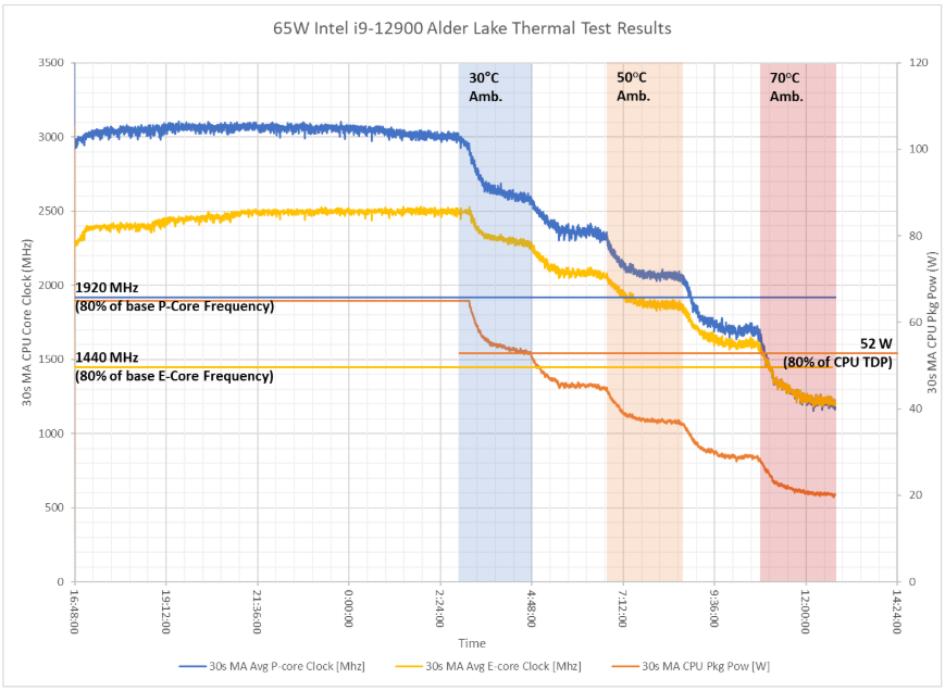
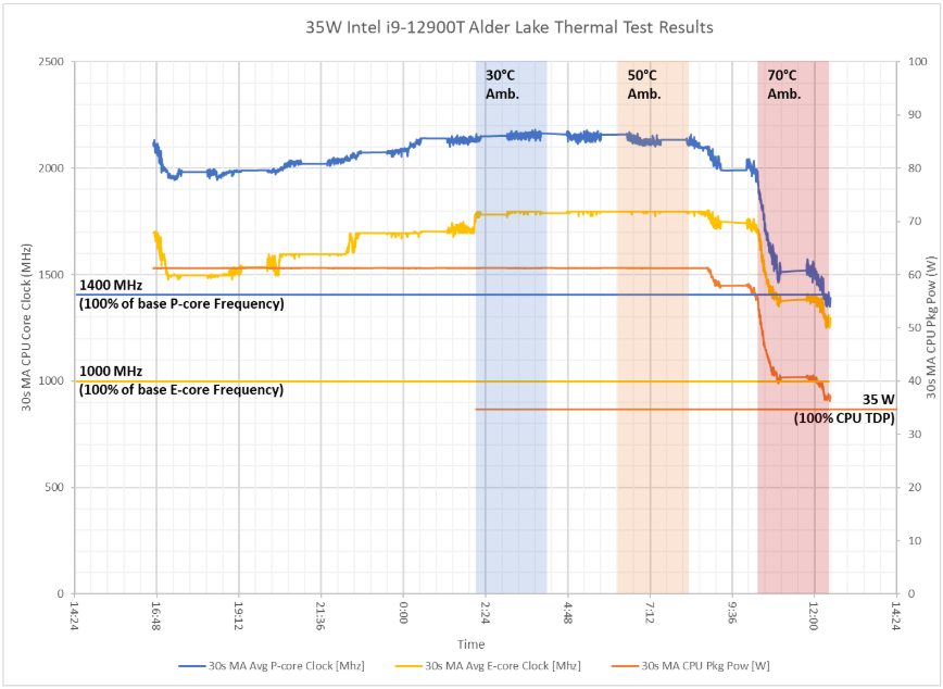
#### Test Conditions
* Temperature Range: 0ºC to 50°C
* Step size: 10°C
* Place the system in a chamber with 0.7 m/s of airflow and run the Furmark stress test
#### Test Results
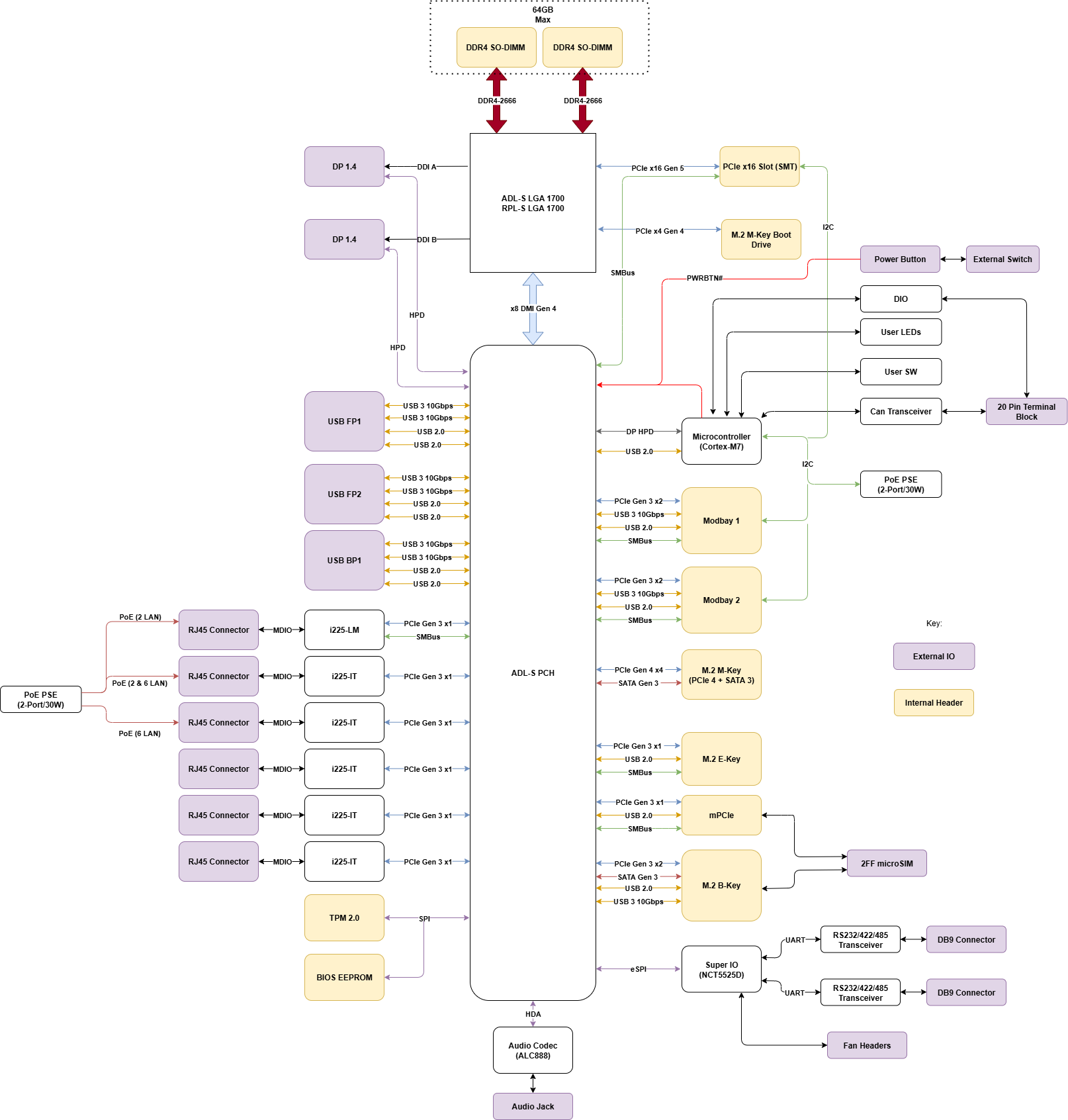
### 2.7- Block Diagram
## 3- Installation & Mechanical
#### Dimensions
### 3.1- Mounting
#### DIN Rail Mounting (MTD109)
**Step 1:** Align the two screw holes on the back of the system with the respective holes on the DIN Clip (MTD109).
**Step 2:** Attach DIN Clip (MTD109) to the system using the supplied M3 screws (M3X0.5 Flathead Screw, 6mm Long).
**Step 3:** Mount system onto the DIN rail.
*Note: The mounting brackets are required to support 4x the hanging weight of the system.*\
*The mating surface and hardware must be capable of supporting the same load.*
#### VESA Mounting (MTW117)
**Step 1:** Align the two screw holes on the back of the system with the respective holes on the VESA mounting bracket (MTW117).
**Step 2:** Attach VESA Mounting Bracket (MTW117) to the system using the supplied M3 screws (M3X0.5 Flathead Screw, 6mm Long)
#### Rubber Feet (MTF100)
**Step 1:** Peel feet from releasing paper.
**Step 2:** Adhere feet on the bottom side or CL260.
### 3.2- Internal Access
Properly opening OnLogic systems does not void the warranty in most cases, however, some precautions are necessary to avoid damaging the system.
* Perform this disassembly in an area free of static discharge.
* Disconnect power, video, and any other connections to the system. It should be fully unplugged.
* Ideally, wear a grounding strap. If that is not available, regularly touch a grounded metal surface to discharge your body of static electricity.
{% hint style="info" %}
It is recommended that this is to be performed by skilled personnel.
{% endhint %}
### 3.3- CAD & Drawings
#### CL260 CAD Files
{% file src="/files/VtAgTPvVZ47O3Q719ZWY" %}
{% file src="/files/zBEdyBoI56HgZOLNPVJr" %}
{% file src="/files/Evrqs8285ETAbl2OI5ly" %}
#### CL260 Mounting Dimensional Drawings
{% file src="/files/xH6TxEayDxHZwtTNh6p6" %}
## 4- Software & Firmware
### 4.1- Drivers & Downloads
Windows 11 Drivers - [Download](https://static.onlogic.com/resources/drivers/CL200_Series/CL260/V1.00_Production.zip)
(Follow our guide for [Installing Drivers via Device Manager](/support-articles/how-tos/operating-systems/windows/update-system-drivers))
### 4.2- BIOS
#### BIOS manual
For the full BIOS manual, please [click here](/product-documentation/industrial-products/cl200-series/cl260/cl260-bios-manual).
#### BIOS Updates
| Version | Details | Link |
| ------- | ------------------ | ------------------------------------------------------------------------------------ |
| 1.05E | Production Version | [Download](https://drive.google.com/drive/folders/1-tObqgRKxWgVdfTMAsHkCLTupoYkhAZP) |
*\*Update the BIOS with the file(s) above. You can follow this* [*how-to*](/support-articles/how-tos/firmware-bios-drivers/update-efi-bios) *guide for installation instructions. **PLEASE NOTE -** this is a SIGNED BIOS.*
### 4.3- Features & Configuration
#### How to configure Serial port for RS232/422/485
The BIOS controls the serial port configurations. Go to the following BIOS settings to adjust the communication types. Access the BIOS by pressing \ at boot up.
Set the communication type, navigate to:
**Advanced –> Serial Port**
* RS232 (default)
* RS422
* RS485
Make sure to save any changes by pressing F10 to Save and Exit.
## 5- Support & Compliance
### 5.1- Troubleshooting & FAQ
#### Factory Reset
The CL260 features a factory reset button to manually restore the BIOS to its default settings.
1. Locate the factory reset button on the front plate.
2. Press the reset button to restore system BIOS settings back to factory defaults or custom set values.
#### RS232/422/485 Information
120-ohm termination resistor:
For RS-422 and RS-485, the internal 120Ω termination resistor is enabled by default.
RS-485 Built-in biasing/fail-safe:
The transceiver supports enhanced fail-safe operation and does not require external biasing resistors to maintain a defined receiver state when the bus is idle.
Standard RS-485 biasing:
The transceiver implements an enhanced fail-safe receiver function. When the bus is open, shorted, or idle (un-driven), the receiver output is guaranteed to remain at a logic-high state. Therefore, no external RS-485 biasing resistors are required.
### 5.2- Regulatory
#### CE
This device has been tested to the relevant EMC and Safety standards. Modifications by the user may invalidate certifications. Testing included EN 55032, EN 55035, EN 60601-1-2, EN 62368-1, EN 18031-1 (RED 3.3d) and IEC 60945 Ed. 4.
#### FCC Statement
This device complies with part 15 of the FCC rules as a Class A device. Operation is subject to the following two conditions: (1) this device may not cause harmful interference and (2) this device must accept any interference received, including interference that may cause undesired operation.
#### ISED (Innovation, Science and Economic Development Canada)
This device complies with Industry Canada license-exempt RSS standard(s). Operation is subject to the following two conditions: (1) this device may not cause interference, and (2) this device must accept any interference, including interference that may cause undesired operation of the device.
Le présent appareil est conforme aux CNR d'Industrie Canada applicables aux appareils radio exempts de licence. L'exploitation est autorisée aux deux conditions suivantes : (1) l'appareil ne doit pas produire de brouillage, et (2) l'utilisateur de l'appareil doit accepter tout brouillage radioélectrique subi, même si le brouillage est susceptible d'en compromettre le fonctionnement.
#### **CAN ICES-003(A) / NMB-003(A)**
#### UKCA
The computer system was evaluated for medical, IT equipment, automotive, maritime and railway EMC standards as a class A device. The computer complies with the relevant IT equipment directives for the UKCA mark.
#### Download Documents
{% file src="/files/rtOpNAn1irbX8N0ydT6I" %}
{% file src="/files/Lxep81e8X6CJAm9cLVPt" %}
{% file src="/files/swgdVDaJG8r1lE9r9B3F" %}
{% file src="/files/h8QfpNh3MLnbnAOCYYtr" %}
{% file src="/files/mTIfX4J6LmmrWYcKXX51" %}
{% file src="/files/LoO0IZZXMfHRBr1Hvsk6" %}
{% file src="/files/sYKxgJOwlaeYPxqNtOKn" %}
{% file src="/files/isq4tVQ5Ks4F75Y84qOH" %}
### 5.3- Security Advisory
For the latest security advisories concerning OnLogic products, including vulnerability disclosures and necessary updates, please refer to our official Security Advisories page. It is recommended to regularly check this resource for critical security information.\
[**Access Security Advisories**](/support-articles/security-advisories)
# CL260 BIOS Manual
BIOS Version 1.04
## 1- Getting Started
### 1.1 - Introduction
The UEFI BIOS is a small program which runs when your computer starts and configures its basic functions. That configuration is automatic, and most users will be satisfied with the default configuration. If the default configuration is not sufficient, the BIOS has setup menus which can be used to reconfigure the computer.
The purpose of this manual is to document the function of the BIOS and its available configuration options. The text of this document lists the BIOS menus and options exactly as they appear in the BIOS menus: in the correct order, with the correct default values for this BIOS version. Some options are hidden based on how other options are set and which hardware is detected in the system, so some options may not appear on all systems. Informative screenshots are also provided throughout, but their contents may not exactly match this BIOS version.
### 1.2 - Navigating the Setup Menu
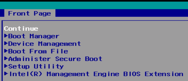
To access the BIOS setup menu, hold the DEL key on the keyboard while turning on the system. After a few seconds, the BIOS front page menu is shown:
On each menu, the selected option is shown in white, other options are shown in blue, and read-only options are shown in gray. Some menus have multiple screens, which are shown at the top of the screen. The active screen is shown with a gray background and inactive screens are shown with blue backgrounds.
BIOS menus are navigated by pressing keys on the keyboard:
* F1 shows help on available keyboard shortcuts
* ↑/↓ arrow keys select the option above or below the currently-selected option
* →/← arrow keys activate the screen to the right or left of the currently-activated screen
* Enter activates the selected option. If that option is a menu, it is opened. If it is a configuration option, a dialog is opened to select a new value.
* F5/F6 change the selected option to its previous or next value
* Esc returns to the previous menu
* F9 restores all options to their factory default values
* F10 saves all options and restarts the system
### 1.3 - Boot manager
To access the BIOS boot manager, hold the F10 key on the keyboard while turning on the system. After a few seconds, the BIOS boot manager is shown:
## 2- Onlogic Features
### 2.1 - Secure Boot
To access the Secure Boot Menu, hold the **Ctrl+Alt+F4** key on the keyboard while turning on the system. After a few seconds, the Secure Boot menu is shown:
* The system will prompt you to set admin passwords to configure secure boot for the first time.
* Enter the admin password to access the secure boot setting page.
### 2.2 - Error LED
The Error LED is effectively controlled by BIOS based on the following conditions:
| **Faulty condition** | **Error LED** | **When to detect** |
| ---------------------------- | ------------- | ------------------ |
| DIMM error | Constant on | At BIOS boot-up |
| No boot device found | Slow blinking | At BIOS boot-up |
| RTC coin cell battery < 2.5V | Fast blinking | At BIOS boot-up |
Blinking frequencies:
* Slow blinking: 0.5 Hz (Blinks once every two seconds)
* Medium blinking: 1 Hz (Blinks once every second)
* Fast blinking: 4 Hz (Blinks four times every second)
### 2.3 - Low RTC Battery Voltage Warning
When RTC battery is low, BIOS will display "Warning: Low RTC battery" for 30 seconds during the BIOS POST.
### 2.4 - Crisis Recovery
If a BIOS update is interrupted, your system may fail to boot. The system will attempt to recover in two ways:
**1. Automatic Recovery**
The system will automatically try to restore the original BIOS image.
* Look for the text "Crisis Recovery" on your screen.
* This indicates the repair is in progress.
**2. Manual Recovery (USB Method)**
If the system keeps rebooting and does not recover automatically, follow these steps:
1. Save a valid BIOS image file onto a USB flash drive.
2. Rename the file to: `CL260.bin`
3. Insert the USB drive into the computer.
4. The system will automatically find the file and repair the BIOS.
### 2.5 - Factory Reset Button
You can enable the Factory Reset Button under Onlogic Feature Configuration of the BIOS setup menu
#### How to Perform a Factory Reset
1. Turn off the system completely.
2. Press and hold the Factory Reset button.
3. While still holding Reset, press the Power button to turn the system on.
4. Wait 5 seconds after the system powers up, then release the Factory Reset button.
The Result:
* All BIOS settings return to default.
* Admin passwords are deleted.
### 2.5 - SSD S.M.A.R.T Health Check
SSD S.M.A.R.T Health Check is enabled by default in the Onlogic Feature Configuration
BIOS will check the SSD health status and display warnings if the status is bad for 30 seconds
### 2.6 - System Watchdog Timer
* Normal Operation: Once the computer boots to an OS, the BIOS constantly resets a hidden countdown timer to prove the system is still running smoothly.
* If the system freezes ("hangs") and stops working, it fails to reset that timer.
* When the timer runs out (hits zero), it automatically forces the computer to restart to recover from the freeze.
### 2.7 - To Enable In-Band ECC
To enable In-Band ECC in the memory configuration page, Intel Trusted Execution Technology must be disabled in the CPU configuration page.
## 3 - Main Menu
Several options are available on the Main page:
* Platform information: a comprehensive summary of the computer's hardware components and firmware details
* Language: Select which language to display
* System Time: adjust RTC time
* System Date: adjust RTC date
## 4 - Advanced Menu
The Advanced menu contains the following options:
* BT
* Enable/Disable BT module
* WIFI
* Enable/Disable WiFi module
* LAN WAKE
* Enable/Disable LAN WAKE
* USB Type-A S4/S5 keep power
* Enabled to make USB A continue to supply power in S4/S5
* Serial Port
* Select RS485/RS422/RS232/Loopback function
* Hardware Monitor
* Display voltage information
* Onlogic Feature Configuration
* Onlogic features described in Section 2 above
* **RC Advanced Menu**
* Advanced settings on platform
* **Boot Configuration**
* Configure boot settings
* Advanced Platform Information
* Console Redirection Configuration
* Console redirection allows the input and output of a computer's console to be rerouted to another device or location, often for remote management or troubleshooting.
### 4.1 - RC Advanced Menu - Turbo Mode
Enabling Turbo Mode on the CL260 Description By default, Turbo Mode is disabled in the shipping BIOS to prevent total power consumption from exceeding the maximum output of the power adapter, particularly when Power over Ethernet (PoE) is utilized to power external devices.
If you are not using PoE as a power source, you may follow the instructions in this guide to enable Turbo Mode via the BIOS Setup Utility.
#### Instructions for Enabling Turbo Mode
1. Power on the system and press \[DEL] to enter the BIOS Setup Utility. Navigate to the \[Advanced] tab and select \[RC Advanced Menu].
2. Within the \[RC Advanced Menu], select \[Power & Performance].
3. In the \[Power & Performance] menu, select \[CPU Power Management Control].
4\. Locate \[Turbo mode] at the top of the menu. Select this item and press \[ENTER] to change the value from \[Disabled] to \[Enabled]. No other settings need to be modified.
5\. Press \[F10] to save your changes and exit the BIOS Setup Utility. Turbo Mode is now enabled on your CL260.
## 5 - Security Menu

The Security menu contains the following options:
* **Current TPM Device** (read-only; possible values: Not Detected, TPM 1.2, TPM 2.0)
* **TPM Active PCR Hash Algorithm** (read-only)
* **TPM Hardware Supported Hash Algorithm** (read-only)
* **BIOS Supported Hash Algorithm** (read-only)
* **TrEE Protocol Version** (default value: 1.1; possible values: 1.0, 1.1)
* **TPM Availability** (default value: Available; possible values: Available, Hidden) When Hidden, don’t exposes TPM to OS
* TPM Operation - a command setting that tells the computer what to do with the security chip the next time it reboots.
## 4 - Power Management Menu
The Power menu contains the following options:
* **Wake on RTC from S5**
* Auto wake on S5, By Day of Month or Fixed time of every day
* **Restore AC Power Loss**
* Select Power Off/ Power On/ Last State after power loss restore
## 5 - Boot Menu
The Boot menu contains the following options:
* **Network Stack**
* Network Stack Support: Windows 8 BitLocker Unlock, UEFI IPv4/IPv6 PXE, Legacy PXE OPROM
* **PXE Boot capability**
* Disabled : Support Network Stack
* UEFI PXE : IPv4/IPv6
* Legacy : Legacy PXE OPROM only
* **Boot Device Type Order**
* Change boot device type order
* **Hard Disk Drive**
* Change hard drive boot order
* **Others**
* Changer other device boot order
## 6 - Exit Options

The exit screen provides options to leave the setup utility and to load and save settings.
* **Exit Saving Changes**: saves the current configuration and restarts the system to apply it
* **Save Change Without Exit**: saves the current configuration but does not restart the system
* **Exit Discarding Changes**: returns to the front page without saving or applying the current configuration
* **Load Optimal Defaults**: loads the factory default configuration
* **Load Custom Defaults**: loads a previously saved custom configuration
* **Save Custom Defaults**: saves the current configuration so it can be loaded later
* **Discard Changes**: restores the current configuration to its original state
# FR101 Series
# FR101
FR101 Computer Product Manual
## 1 - Product Overview
### 1.1 - Introduction
The OnLogic FR101 computer harnesses the advanced power and integrated edge AI capabilities of the Qualcomm QCS6490 Integrated ARM CPU. This is a versatile AI computing device capable of delivering AI inference capabilities in a fanless, industrial design. Engineered for the evolved edge, with a 0°C to 50°C operating temperature range, the FR101 thrives in a diverse range of industrial applications. The Qualcomm Dragonwing™ QCS6490 processor is purpose-built for high-performance edge computing, combining up to 8-core Qualcomm® Kryo™ CPUs, integrated Qualcomm® Adreno™ GPU, and a powerful AI engine (NPU + DSP), delivering up to 12 dense TOPS. These platforms enable real-time, on-device processing for compute-intensive applications like autonomous robotics, smart vision, and industrial automation.
For more information on accessories and additional features, visit the FR101 product page:
* [https://www.onlogic.com/store/fr101](https://www.onlogic.com/store/fr101/)
### 1.2 - Safety Safety Precautions, Safeguards & Information
Do not open and modify the device! The device complies with various national and international Safety, EMC and Environmental requirements per various standards.
Modification of the device may void certifications, warranty and/or cause possible injury to the user.
Safe use and installation instructions
1. Care must be taken handling the device to prevent injury to self or possibility of damaging\
the unit.
2. Read the entire manual before using the product.
3. Install the device securely per users manual instructions.
4. Wall or ceiling mounting device requires use of OnLogic mounting plate or bracket.
5. Use M3x0.5mm Flat Head screws to attach mounting plate or mounting brackets to threaded holes on bottom or rear of chassis. Screws should be a minimum length of 4mm. Add 1mm of screw length for every mm of additional thickness of plate or bracket beyond 1.5mm.
6. **Caution, Hot Surface!** It is normal for the unit to heat up and be hot to touch. **Do not touch** the heatsink area or enclosure during operation and 30 minutes after shutdown allowing the unit to cool down.
7. Ambient operating temperature must be between -20 °C to 60 °C with a non-condensing relative humidity of 10-85%.
8. The device can be stored at temperatures between -20 °C to 85 °C. Note: Unit must be stabilized within operating temperature before use, minimum 3HR.
9. Keep the device away from liquids and flammable materials. Not to be installed in a hazardous environment.
10. Do not clean the device with liquids. The chassis can be cleaned with a dry cloth or duster only. To prevent injury to self and/or damage to the device the unit must be powered down and all connecting power and other peripherals shall be disconnected prior to cleaning.
11. Allow adequate space around all sides of the device for proper cooling and to not exceed its maximum operating temperature limit. If the device is mounted to a vertical surface then recommended device orientation is such that heatsink fins allow air to rise unobstructed. Alternative orientations may result in reduced operational temperature range.
12. This device is intended for indoor operation only.
13.  **Caution, Risk of Electric Shock!** Unit is powered by low voltage DC (Direct Current) only! Do not connect AC (Alternating Current) into the device!
14. To power the device use only UL ITE Listed external power supplies with DC output of 12-24VDC, see specs for details.
15. Install the device only with shielded network cables.
16. The installer should be experienced in aftermarket installation and familiar with general practices for installing electronics.
17. Service and repair of the device must be done by qualified skilled service personnel. This includes, but is not limited to, replacement of the CMOS battery. Replacement CMOS battery must be UL recognized and of a similar type as the original.
18. Proper disposal of the CMOS battery must comply with local governance.
19. This equipment is not suitable for use in locations where children are likely to be present.
 **WARNING:** There is danger of explosion if the CMOS battery is replaced incorrectly. Disposal of battery into fire or a hot oven, or mechanically crushing or cutting of a battery can result in an explosion.
Précautions et guide d’installation
Ne pas ouvrir et modifier l'appareil ! L'appareil est conforme à diverses exigences nationales et internationales en matière de sécurité, de CEM et d'environnement selon diverses normes.
La modification de l'appareil peut annuler les certifications, la garantie et/ou causer des blessures à l'utilisateur.
Instructions d'utilisation et d'installation en toute sécurité
1. Des précautions doivent être prises lors de la manipulation de l'appareil pour éviter de se blesser ou d'endommager l'appareil.
2. Lisez l'intégralité du manuel avant d'utiliser le produit.
3. Installez l'appareil en toute sécurité selon les instructions du manuel de l'utilisateur.
4. Pour vous protéger contre une exposition RF excessive, maintenez au moins 20 cm de tout utilisateur et des antennes RF. Utilisez uniquement les antennes double bande fournies avec un gain de 2 dBi/2 dBi.
5. Le dispositif de montage mural ou au plafond nécessite l'utilisation d'une plaque ou d'un support de montage. La plaque ou le support doit être en métal et avoir une épaisseur minimale de 1 mm.
6. Utilisez des vis à tête plate M4x0,5 mm pour fixer la plaque de montage ou les supports de montage aux trous filetés au bas ou à l'arrière du châssis. Les vis doivent avoir une longueur minimale de 4 mm. Ajoutez 1 mm de longueur de vis pour chaque mm d'épaisseur supplémentaire de plaque ou de support au-delà de 1,5 mm.
7. **Attention surface chaude!** Il est normal que l'appareil chauffe et soit chaud au toucher. Ne touchez pas la zone du dissipateur thermique ou le boîtier pendant le fonctionnement et 30 minutes après l'arrêt pour permettre à l'unité de refroidir.
8. La température ambiante de fonctionnement doit être comprise entre -20 °C et 60 °C avec une humidité relative sans condensation de 10 à 85 %.
9. L'appareil peut être stocké à des températures comprises entre -20 °C et 85 °C. Remarque : L'unité doit être stabilisée à la température de fonctionnement avant utilisation, minimum 3 heures.
10. Gardez l'appareil à l'écart des liquides et des matériaux inflammables. Ne pas installer dans un environnement dangereux.
11. Ne nettoyez pas l'appareil avec des liquides. Le châssis peut être nettoyé uniquement avec un chiffon sec ou un plumeau. Pour éviter de se blesser et/ou d'endommager l'appareil, l'appareil doit être éteint et toutes les alimentations et autres périphériques doivent être déconnectés avant le nettoyage.
12. Prévoyez un espace suffisant autour de tous les côtés de l'appareil pour un refroidissement correct et pour ne pas dépasser sa limite de température de fonctionnement maximale. Si l'appareil est monté sur une surface verticale, l'orientation recommandée de l'appareil est telle que les ailettes du dissipateur thermique permettent à l'air de monter sans obstruction. Des orientations alternatives peuvent entraîner une plage de températures de fonctionnement réduite.
13. Cet appareil est destiné à une utilisation en intérieur uniquement.
14. **Attention, risque de choc électrique !** L'unité est alimentée uniquement par une basse tension CC (courant continu) ! Ne connectez pas le courant alternatif (courant alternatif) à l'appareil !
15. Pour alimenter l'appareil, utilisez uniquement des alimentations externes répertoriées UL ITE avec une sortie CC de 12-24 VCC, voir les spécifications pour plus de détails.
16. Les méthodes de câblage utilisées pour le raccordement de l'équipement à l'alimentation secteur doivent être conformes au Code national de l'électricité, NFPA 70, et au Code canadien de l'électricité, Partie I, CSA C22.1.
17. Prévoyez suffisamment d'espace pour les connexions de câblage du bornier afin que les fils ne se plient pas et soient protégés contre les dommages accidentels.
18. Installez l'appareil uniquement avec des câbles réseau blindés.
19. L'installateur doit avoir de l'expérience dans l'installation de pièces de rechange et être familiarisé avec les pratiques générales d'installation de composants électroniques.
20. L'appareil radio n'est pas destiné aux services d'urgence.
21. L'entretien et la réparation de l'appareil doivent être effectués par un personnel qualifié. Cela inclut, mais sans s'y limiter, le remplacement de la batterie CMOS. La batterie CMOS de remplacement doit être du même type que celle d'origine.
22. L'élimination appropriée de la batterie CMOS doit être conforme à la gouvernance locale.
23. Le produit doit uniquement être connecté à un routeur, un commutateur ou un équipement réseau similaire certifié
24. Le produit est destiné à une utilisation en intérieur uniquement.
25. Le produit ne peut pas être connecté au réseau public.
26. Cet équipement n'est pas adapté à une utilisation dans des endroits où des enfants sont susceptibles d'être présents.
**ATTENTION:** Il existe un risque d'explosion si la pile CMOS n'est pas remplacée correctement. L'élimination de la batterie dans le feu ou dans un four chaud, ou l'écrasement ou le découpage mécanique d'une batterie peut entraîner une explosion.
### 1.3 - Box Contents & Accessories
* 1x 19V Power Supply
* 1x 16-pin DIO Terminal Block
\
All drivers and product guides can be found on the corresponding product page. For more information on accessories and additional features, visit the FR101 Product Page:
[https://www.onlogic.com/store/fr101](https://www.onlogic.com/store/fr101/)
### 1.4 - Product Specifications
Model
System SKU
System Dimensions
94mm x 157mm x 70.75mm
530 g
CPU
8-Core Qualcomm® Kryo™ 670 Up to 2.1 GHz
GPU
Qualcomm® Adreno™ 643
AI Performance
Qualcomm® Hexagon™ 770
Up to 12 Dense TOPS (Tera Operations Per Second)
Memory
8GB LPDDR4x
Storage
128GB UFS Flash
Networking
Ethernet support through QPS615
Right I/O
1x Status LED
1x Power Button
1x Recovery Button
1x Reset Button
1x Function Button
Front I/O
1x 1GbE LAN (RJ45)
1x 10GbE LAN (RJ45)
4x USB 3.0 Type-A
1x USB 3.0 Type-C
1x HDMI (Maximum Resolution 1920x1080@60Hz)
1x Barrel Jack Power DC 19V
Rear I/O
Digital In/Digital Output (4 DI ports (5V) & 4 DO ports)
US, Canada, UK, EU, Japan, South Korea, Australia, New Zealand, China, India, Mexico, Brazil, Singapore, Hong Kong, Saudi Arabia, UAE
## 2 - Technical Specifications
### 2.1 - External Features
#### Front I/O
#### Right I/O
Button Defintions:
Button
Description
Power Button (Press)
Software Shutdown (Ubuntu Only)
Power Button (Hold - 8 sec)
Reset (Reboot)
FN1 Button (Press)
Send hotkey code (Kcode: F1)
FN1 Button (Hold - 8 sec)
Hardware shutdown (Reboots if connected to USB-C)
FN2 Button
Send hotkey code (Kcode: F2)
FN3 Button
Send hotkey code (Kcode: F3)
Status LED
| Scenario | LED Behavior |
| --------------------- | ------------ |
| System off with power | Dark |
| Booting | Steady Blue |
| Power on and ready | Steady Teal |
#### Back I/O
### 2.2 - I/O Definitions
#### Front I/O Definition
#### DC-IN
Mainboard power is applied to the Factor 101 platform by way of a female barrel jack connector. The system is operational at 19V DC.
#### USB-C
A USB 3.0 Type-C port is provided for peripheral usage and as an additional display output option through Display Port over USB-C. Additionally, the port is used for accessing the system via ADB (Android Debug Bridge). See [Force USB Recovery](#id-4.3-force-usb-recovery) for more information on flashing an operating system through the ADB port.
#### USB 3.0
4 USB 3.0 Type-A ports are provided for peripheral usage.
#### LAN 1
The first LAN port on FR101 supports up to 1Gbps link speeds over standard shielded CAT5e or CAT6 cables. The connector is the industry standard RJ45 connector. The LAN link state is shown by the two LEDs enclosed in the port.
#### LAN 2
The second LAN port on FR101 supports up to 10Gbps link speeds over standard shielded CAT5e or CAT6 cables. The connector is the industry standard RJ45 connector. The LAN link state is shown by the two LEDs enclosed in the port.
The FR101 uses the Qualcomm QPS615 Ethernet-AVB/TSN bridge IC for high-speed interfacing between the host SoC and ethernet devices on the network. Connection to the host is via 2 lanes of PCIe Gen3.
#### HDMI
Resolutions up to 1920x1080 @ 60Hz are supported. In case of interoperability issues between certain monitors and the FR101, connect the HDMI to the external display before powering on the system.
#### Back I/O Definition
#### 8 Channel DIO
The definitions of the digital input/output ports are shown below:
| Port | Value |
| ---- | ----- |
| DI 1 | 309 |
| DI 2 | 310 |
| DI 3 | 311 |
| DI 4 | 312 |
| DO 1 | 305 |
| DO 2 | 306 |
| DO 3 | 307 |
| DO 4 | 308 |
The digital input/output ports can be controlled through the Linux sysfs filesystem.
Example of a digital input port:
```shellscript
echo 309 > /sys/class/gpio/export
echo in > /sys/class/gpio/gpio309/direction
cat /sys/class/gpio/gpio309/value
echo 309 > /sys/class/gpio/unexport
```
Example of a digital output port:
```shellscript
echo 305 > /sys/class/gpio/export
echo out > /sys/class/gpio/gpio35/direction
echo 1 > /sys/class/gpio/gpio305/value
echo 0 > /sys/class/gpio/gpio305/value
echo 305 > /sys/class/gpio/unexport
```
Digital output port reference schematic (open drain/isolation):
The digital output port can drive relay coils with specifications of 12V/24V/40V, with a current limit of 150mA.
### 2.2 - Thermal Results
### 2.3 - Block Diagram
### 2.4 - Power Management
The FR101 supports an input voltage range of 12V-24V. However, to guarantee optimal performance, OnLogic recommends the use of the provided 19V/65W power supply. The approximate maximum power draw of the system under load is about 60W.
## 3 - Installation & Mechanical
### 3.1 - Dimensions
### 3.2 - Mounting
The FR101 supports wall mounting using the integrated mounting brackets.
### 3.3 - Internal Access
OnLogic does not recommend accessing the internals of the FR101 though the removal of any outer plate.
### 3.4 - CAD & Drawings
[FR101 Dimensional Drawings](https://media.onlogic.com/248f8472-1b41-4a43-9f88-4aee598a9ac5/f328330e-9f2c-42ba-9de6-4e5f70e8002b/9UBMmypT6IeIO6QdPOIOatkd5/HVZ3rHtJ3qRGbWOJZ7CuRb2vT.pdf?targetFileName=OnLogic_Factor101_Spec_Sheet.pdf)
{% file src="/files/mvxwx92Nkgg8C8zuXbQh" %}
## 4 - Software & Firmware
### 4.1 - Ubuntu 20.04
The FR101 will arrive imaged with a minimal Ubuntu 20.04 desktop environment. The default user name and password combination is onlogic/onlogic. The default root password is oelinux123, and the user may switch to root mode using `su`.
{% hint style="danger" %}
* `sudo` is not supported
* Do not run `apt upgrade`, as it may break package dependencies.
{% endhint %}
When booting into the operating system directly from the FR101, ensure that "Ubuntu on Wayland" is selected from the bottom right gear icon at login, shown below:
## 5 - Support & Compliance
### 5.1 - Recommended Hardware Configuration
#### Android Debug Bridge (ADB)
Android debug bridge is a command line tool used for accessing the FR101 system over USB-C for moving files, installing packages, or debugging applications. For more information on installation and use, refer to the official [android developer documentation](https://developer.android.com/tools/adb).
### 5.2 - Force USB Recovery
To reflash the system image, the device must enter Force USB Recovery mode to transfer the system image file from a PC/Laptop. The steps to enter EDL (Emergency Download Mode) mode are as follows:
1. Unplug all wires from the FR101 and unplug the USB cable from the imaging device.
2. Hold down the FN2 button with a paper clip.
3. While holding FN2, plug in power to the FR101. Wait 2-3 seconds then remove the paper clip.
4. Plug the USB-C cable in to the FR101.
5. Plug the USB cable into the imaging system.
{% hint style="success" %}
Check for the QDL port from the Ubuntu or Windows imaging system
{% endhint %}
### 5.3 - Flash Operating System
The FR101 supports flashing the integrated UFS via the USB-C port. To re-flash the operating system, first follow the instructions to put the FR101 into [QDL mode](#id-5.2-force-usb-recovery).
{% hint style="danger" %}
Back up any important files on the FR101 device before re-flashing.
{% endhint %}
From a separate Windows PC or laptop:
1. Attach a USB cable to the USB-C port on the FR101. Verify the QDL port is present by opening device manager, and expanding the "Ports" section.
2. Download and extract the 20.04\_onlogic folder from the OnLogic file repository.
3. Navigate to 20.04\_onlogic/image/QFIL\_flat/ufs/ and run \_Burn\_image.bat.
4. When prompted, select option "1b".
5. Once flashing is complete, the tool will automatically reboot the FR101.
For installing additional packages standard to an Ubuntu desktop experience, proceed with the following:
1. Navigate to 20.04\_onlogic/ubuntu/image/
2. On your Windows imaging device, run ubuntu\_preseed.bat
{% hint style="info" %}
Note: This step does not require the device to be in QDL mode.
{% endhint %}
3. Allow the script to complete and reboot the system upon success. You will be met with the Ubuntu login screen requiring the same default passwords and display environment selection mentioned in [4.1](#id-4.1-ubuntu-20.04).
# FR200 Series
# FR201
## 1- Introduction
The Factor 201 (FR201) harnesses the power of the Raspberry Pi Compute Module 4, which provides the core functionality of the Raspberry Pi 4. Combined with our own industry-focused carrier board, and a custom-designed industrial chassis, the Factor 201 has been engineered for today's industrial and embedded applications.
For more information on accessories and additional features, visit the FR201 product page:
*
### 1.2- Safety Safety Precautions, Safeguards & Information
Do not open or modify the device. The device uses components that comply with FCC and CE regulations. Modification of the device may void these certifications.
**Safe use and installation instructions**
1. Install the device securely. Be careful handling the device to prevent injury and do not drop.
2. Wall or ceiling mounting the device requires use of a mounting plate or bracket. The plate or bracket must be of metal construction and have a minimum thickness of 1mm.
3. Use M4x0.5mm Flat Head screws to attach mounting plate or mounting brackets to threaded holes on bottom or rear of chassis. Screws should be a minimum length of 4mm. Add 1mm of screw length for every mm of additional thickness of plate or bracket beyond 1.5mm.
4. Ambient operating temperature must be between 0 °C to 60 °C with a non-condensing relative humidity of 10-90%.
5. The device can be stored at temperatures between -10 °C to 85 °C.
6. Keep the device away from liquids and flammable materials.
7. Do not clean the device with liquids. The chassis can be cleaned with a cloth.
8. Allow at least 2 inches of space around all sides of the device for proper cooling. It is recommended to mount the device such that the metal side plates are vertical to allow air to rise unobstructed. Alternative orientations may result in reduced operational temperature range.
9. This device is intended for indoor operation only.
10. Use UL Listed external power supply with rated output 8-24Vdc
11. Install the device only with shielded network cables.
12. Only use SAE approved cables for automotive installation.
13. The installer should be experienced in aftermarket installation and familiar with general practices for installing electronics devices in vehicles.
14. The device should not be installed in the driver’s area of a vehicle.
15. The device should be mounted in accordance with accepted aftermarket practices and materials for vehicle installation.
16. Only use UL Listed connectors for power and serial.
17. Service and repair of the device must be done by qualified service personnel. This includes, but is not limited to, replacement of the CMOS battery. Replacement CMOS battery must be of the same type as the original.
18. Proper disposal of CMOS battery must comply with local governance.

**WARNING:** There is danger of explosion if the CMOS battery is replaced incorrectly. Disposal of battery into fire or a hot oven, or mechanically crushing or cutting of a battery can result in an explosion.\\
Précautions et guide d’installation

**WARNING:** There is danger of explosion if the CMOS battery is replaced incorrectly. Disposal of battery into fire or a hot oven, or mechanically crushing or cutting of a battery can result in an explosion.
**6.6.2 Instructions d'utilisation et d'installation en toute sécurité**
1. Installez l'appareil en toute sécurité. Manipulez l'appareil avec précaution pour éviter de vous blesser et ne le laissez pas tomber.
2. Le montage mural ou au plafond de l'appareil nécessite l'utilisation d'une plaque ou d'un support de montage. La plaque ou le support doit être en métal et avoir une épaisseur minimale de 1 mm.
3. Utilisez des vis à tête plate M4x0,5 mm pour fixer la plaque de montage ou les supports de montage aux trous filetés au bas ou à l'arrière du châssis. Les vis doivent avoir une longueur minimale de 4 mm. Ajoutez 1 mm de longueur de vis pour chaque mm d'épaisseur supplémentaire de plaque ou de support au-delà de 1,5 mm.
4. La température ambiante de fonctionnement doit être comprise entre 0 °C et 60 °C avec une humidité relative sans condensation de 10 à 90 %.
5. L'appareil peut être stocké à des températures comprises entre -10 °C et 85 °C.
6. Gardez l'appareil à l'écart des liquides et des matériaux inflammables.
7. Ne nettoyez pas l'appareil avec des liquides. Le châssis peut être nettoyé avec un chiffon.
8. Laissez au moins 2 pouces d'espace autour de tous les côtés de l'appareil pour un refroidissement correct. Il est recommandé de monter l'appareil de manière à ce que les plaques latérales métalliques soient verticales pour permettre à l'air de monter sans obstruction. Des orientations alternatives peuvent entraîner une plage de températures de fonctionnement réduite.
9. Cet appareil est destiné à une utilisation en intérieur uniquement.
10. Utilisez une alimentation externe homologuée UL avec sortie nominale 8-24 Vdc
11. Installez l'appareil uniquement avec des câbles réseau blindés.
12. Utilisez uniquement des câbles approuvés par SAE pour une installation automobile.
13. L'installateur doit avoir de l'expérience dans l'installation du marché secondaire et être familiarisé avec les pratiques générales d'installation d'appareils électroniques dans les véhicules.
14. L'appareil ne doit pas être installé dans le poste de conduite d'un véhicule.
15. L'appareil doit être monté conformément aux pratiques acceptées du marché secondaire et aux matériaux d'installation du véhicule.
16. Utilisez uniquement des connecteurs homologués UL pour l'alimentation et la série.
17. L'entretien et la réparation de l'appareil doivent être effectués par un personnel qualifié. Cela inclut, mais sans s'y limiter, le remplacement de la batterie CMOS. La batterie CMOS de remplacement doit être du même type que celle d'origine.
18. L'élimination appropriée de la batterie CMOS doit être conforme à la gouvernance locale.

**AVERTISSEMENT:** Il existe un risque d'explosion si la pile CMOS n'est pas remplacée correctement. L'élimination de la batterie dans le feu ou dans un four chaud, ou l'écrasement ou le découpage mécanique d'une batterie peut entraîner une explosion.
### 1.3- Box Contents & Accessories
* 1x Power Terminal Block
* 1x Com Terminal Block
If you purchased additional items such as mounting brackets, power supplies or terminal block connectors, they will be located in the system box or within the outer shipping carton.
All drivers and product guides can be found on the corresponding product page. For more information on accessories and additional features, visit the Factor 200 Series page.
Factor Series Page:
Factor 201 Product Page:
### 1.4- Product Specifications
Feature Category
Factor 201 Specification
System Dimensions
5.07" x 1.5" x 4"
129 x 38 x 102 mm
Board Dimensions
4.47" x 3.85"
CPU (on solder side of board)
Raspberry Pi CM4 Headers
Memory
CM4-dependent, up to 32GB
LAN Controller
1x Realtek RTL8153B (GbE)
1x from CM4 (GbE)
Expansion
1x M.2 2280 B-Key (USB 3.2 5Gb/s)
1x M.2 2280 B-Key (SATA III)
Back I/O
2x 1GbE LAN
1x 5-pin Serial (RS232/422/485)
3-pin Terminal Block with 12~24 V input
Front I/O
1x USB 3.0 5Gb/s
2x USB 2.0
1x HDMI
1x USB-C for CM4 Programming
1x Reset button
Onboard Headers & Connectors
1x Battery on a cable
1x Raspberry Pi Expansion Header (Female; internal)
1x SPI TPM Header
1x CM4 Boot Mode Select
1x PoE PD Header
1x USB2 Modem Header
Voltage Input
12~24V or PoE PD
Power Input
3-pin Terminal Block or PoE PD via optional add-on
Thermal Standards (Subject to change through RFI and RFQ steps)
Board Operating Temperature: -20-60C
Storage Temperature: -40-85C
Operating Humidity: 10% - 95% (non-condensing)
Extra Chassis Features
4 Antenna holes
M3x0.5 threaded mounting holes
Regulatory
SAFETY IEC/UL/EN 62368-1
EMC CISPR 32/35 Class A
FCC Part 15 Class A
IEC/EN 60601-1-2:2014 EMC Ready
Radio Equipment Directive (2014/53/EU) [Only applicable for configurations with wireless transmitters
RoHS 3 Directive (2015/863/EU)[
WEEE Directive (2012/19/EU)
## 2- Technical Specifications
### 2.1- External Features
#### Top I/O
#### Bottom I/O
### 2.2- I/O Definitions
#### Top I/O Definition
#### USB-C Config Port (CM4 Update)
A USB-C port is provided to connect to the CM4 in USB 2.0 device mode, to update the bootloader firmware or modify the eMMC filesystem in USB MSD mode.
A USB 2.0 host used to connect the FR201 must provide a 5V output in order to enable the USB-C connection to the CM4. System power for the FR201 must also be provided separately via the main power input or optional PoE.
USB 3.x, alternate function modes, and power output are not supported on this connector.
#### HDMI
FR201 uses the CM4’s integrated HDMI to drive the external HDMI Port. Resolutions up to 4096x2304 @ 60Hz are supported. CEC (Consumer Electronics Control) functionality is also supported, depending on software configuration.
#### USB 3.2 Gen1 5Gb/s
One USB 3.2 Gen1 (5Gb/s) port is provided for peripherals or boot media.
By default, this port is disabled during system boot to ensure that the CM4 boots from internal media. This behavior can be changed in software, or via the jumper header located in the center of the motherboard. See the headers section of this manual for more information.
#### USB 2.0
Two USB 2.0 ports are provided for peripheral usage. Together, they may deliver a maximum of 2A at 5V, depending on peripheral and device configuration.
#### Reset Button
The front reset button can be used to trigger a reset of the CM4. The reset button is a momentary contact button that is tool-accessible through the chassis.
#### Bottom I/O Definition
#### 3-Pin Terminal Block Power Connector
Mainboard power is applied to the FR201 platform by way of a 3-pin terminal block connector (Mating part: Dinkle 2ESSM-03P or equivalent). The system is operational from 8V\~24V. The maximum rated current of the connector is 15A per pin. Use a wire gauge that is rated for the operational current. See below for on-board connector pinout.
**Note: DC power input should not be connected when the system is supplied with POE power via the add-on module.**
3-Pin terminal power pinout
#### 5-Pin COM Terminal Block
The serial port supports RS-232, RS-422, and RS-485 configurations by way of a 5-pin terminal block connector (Mating part: Dinkle 0221-2005 or equivalent). The mode can be selected from within the operating system using available configuration tools. See FR201 software documentation for details.
COM terminal pinout
#### LAN1 - CM4 Driven
The CM4 LAN Port on FR201 supports up to 1Gbps link speeds over standard shielded CAT5e or CAT6 cables. The connector is the industry standard RJ45 connector. The LAN link state is shown by the two LEDs enclosed in the port. Activity is also indicated by the LAN1 LED on the side of the system. The default configuration is included below, but the behavior can be customized using the CM4 boot configuration file.
PoE PD (power input) support is available optionally by adding the ADP125 FR200 isolated POE PD module to the system.
**Note: DC power input should not be connected when the system is supplied with POE power via the non-isolated ADP122 add-on module.**\\
LAN activity light description
#### LAN2 - Realtek RTL8153B
The second LAN Port on FR201 supports up to 1Gbps link speeds over standard shielded CAT5e or CAT6 cables. The connector is the industry standard RJ45 connector. The LAN link state is shown by the two LEDs enclosed in the port. The description is included below. Activity is also indicated by the LAN2 LED on the side of the system.
LAN activity light description
#### Expansion Port Pinout
#### M.2 B-Key (MODEM)
#### M.2 B-Key (SATA)
### 2.3- Motherboard Connectors
#### M.2 B-Key
An M.2 B-Key port is present on the FR201 motherboard to allow support for B-Key form-factor expansion cards. Supported cards include 3042, 2242, and 2260 form-factors with an adapter and 2280 form-factor without. The B-Key connector at A14 on the FR201 platform supports SATA Gen I (1.5Gbps), SATA Gen II (3.0Gbps), and SATA Gen III (6.0Gbps) devices. The B-Key connector at A15 on the FR201 platform supports USB 3.2 5Gb/s and USB 2.0 devices.
A full pinout table for this expansion slot is provided in section [2.2- I/O Definitions](#r030936jpohs).
#### Boot Function Jumper Header
A 2mm pin header and jumpers are used to configure some CM4 boot settings.
To enable booting from media attached to the USB3 port, short pins 5 and 6 and apply power to the system.
To disable write-protect for the bootloader, short pins 3 and 4 and apply power.
To disable OS boot and place the CM4 in bootloader update mode, short pins 1 and 2 and apply power. The system will wait for a connection from an outside system via the USB-C configuration port in order to perform firmware updates.
ATX/CMOS header pinout
#### RTC Battery Header
The RTC battery on the FR201 platform is used to retain platform settings and maintain the real-time clock for the system. If the RTC battery is low, CMOS settings will not be retained and you may receive an alert in the operating system. The cabled RTC battery should be replaced with a Maxell CR2032-WK11 (or UL listed equivalent). An equivalent battery shall use a Hirose DF13-2S-1.25c connector to mate with the on-board connector.
#### Raspberry Pi Header
The Raspberry Pi header is designed to mimic the header on the standard Raspberry Pi 4, with additional features. For a detailed list of standard features that this header supports, see the Raspberry Pi documentation. The connector on the Factor 201 is female, but is pinned such that a developer can install a male-to-male interposer and use it as a standard hat header, if the developer notes the following changes:
1. A USB2.0 connection is added at pins 41 & 42.
2. The header’s I2C connection (typically noted as ID\_SC and ID\_SD) is changed to the system I2C bus, rather than the Raspberry Pi ID bus.
3. The header’s GPIO16, 18, 20, & 21 connections are shared with the TPM (configured as SPI6 when installed). If TPM support is desired, developers must avoid implementing these pins on the expansion header as well.
Raspberry Pi header pinout
#### DSI Header (Not Populated)
The DSI (MIPI display) header is pinned identically to the Raspberry Pi 4 DSI header, but is not implemented or installed by default, and is not supported at this time.
#### CSI Header (Not Populated)
The CSI (MIPI camera) header is pinned identically to the Raspberry Pi 4 DSI header, but is not implemented or installed by default, and is not supported at this time.
#### POE Add-on Connector
The POE PD Add-on connector is designed to support the OnLogic ADP125 POE PD add-on module. Other uses are not supported.
\
The ADP125 is an isolated PoE PD (powered device) modules. Factor series systems configured and shipped in **August 2024** or later have this version of the module. This offers isolation/protection from transient voltage of up to 100KV.
#### CM4 Headers
The dual-header CM4 connectors support installation of Raspberry Pi CM4 modules. Two mounting standoffs are included to secure the module.
### 2.4- Raspberry Pi Documentation
Access the official Raspberry Pi Documentation [here](https://www.raspberrypi.com/documentation/).
### 2.5- Power Management
#### Input Voltage Qualification
The base FR201 system is capable of operation with an input voltage ranging from 12V - 24V DC, however different configurations will impact total system draw and may limit input voltage flexibility in the final application.
#### Power Consumption
The power consumption of the Factor 201 was measured for various system configurations, workloads, and power states at both 12V and 24V system input voltages. Tests were performed using Burnintest v9.0 build 1012 to stress system components with and without graphics enabled. The build configurations and power consumption are listed in the tables below.
\
\*The configurations below are using representative samples of internal devices, the specific components mentioned below may vary from the devices provided by OnLogic.
The power consumption for each system configuration is record below
#### Protection Circuitry
These DC levels specified are the absolute max values for the pins for function and safety of the system. The protection circuitry allows for brief transient voltages above these levels without the system turning off or being damaged. A transient voltage suppressor on the power input allows momentary excursions above stated limits.
### **2.6- Thermal Results**
The thermal performance of the FR201 was validated by loading the system to simulate expected workloads while the test system was exposed to high ambient temperatures in a thermal chamber environment. Two different workloads were considered, a 4 core load for heavy processing and a single core workload to evaluate single thread performance. In each workload, the system was run at 100% load for 45 seconds and then the load was removed for a 15 second rest. In order to profile performance at a variety of thermal conditions, the thermal chamber temperature was raised from 40°C to 60°C with a 4 hour dwell at each 5° increment. CPU clock speeds were measured for the duration of the tests. The results were analyzed by comparing the average clock speed over the duration of the test to the expected base clock speed. In the 4 core test, CPU throttling was observed beginning at 50°C, with performance gradually decreasing to just above the maximum throttle state (600 MHz) at 60°C. In the single thread test, throttling does not begin until 55°C, with average frequency remaining above 900 MHz at 60°C.
***FR201 - 4 Core 75% Load Thermal Testing Graph** - The image below shows the thermal test results from an FR201 in a thermal chamber with 75% full 4 core workload (45s at 100% followed by 15s rest) over a temperature range from 40-60°C with a 4 hour dwell every 5°C.*
***FR201 - 4 Core 75% Load Thermal Testing Results Table** - The table below shows the key component temperature values from the above test*
***FR201 - Single Thread 75% Load Thermal Testing Graph** - The image below shows the thermal test results from an FR201 in a thermal chamber with 75% single thread workload (one core at 75% for 45s followed by 15s rest) over a temperature range from 40-60°C with a 4 hour dwell every 5°C.*
***FR201 - Single Thread 75% Load Thermal Testing Results Table** - The table below shows the key component temperature values from the above test.*
### 2.7- Block Diagram
## 3- Installation & Mechanical
### 3.1- Dimensions
### 3.2- Mounting
For a full set of mounting options and instructions, see the [FR201 Spec Sheet & Dimensional Drawings](https://static.onlogic.com/resources/spec-sheets/OnLogic-FR201-SpecSheet-V1.pdf).
### 3.3- Internal Access
Properly opening OnLogic systems does not void the warranty in most cases, however, some precautions are necessary to avoid damaging the system.
* Perform this disassembly in an area free of static discharge.
* Disconnect power, video, and any other connections to the system. It should be fully unplugged.
* Ideally, wear a grounding strap. If that is not available, regularly touch a grounded metal surface to discharge your body of static electricity.
For instructions on how to disassemble the FR201, see [Factor Series Technical Support](/support-articles/how-tos/firmware-bios-drivers/fr201-and-fr202-technical-resources#disassembly) in [Factor Series Technical Support](/support-articles/how-tos/firmware-bios-drivers/fr201-and-fr202-technical-resources).
### 3.4- CAD & Drawings
[FR201 Spec Sheet & Dimensional Drawings (228 KB)](https://media.onlogic.com/248f8472-1b41-4a43-9f88-4aee598a9ac5/48741cd7-d47c-4e7c-ac45-62c449493a73/fYRISE98aKAsXRdwaPHvYfFZA/m5F4jL3Zwb54tggPMP0hfp65p.pdf?targetFileName=OnLogic-FR201-SpecSheet-Dimensions-v2.pdf)
[NWK300 Spec Sheet](https://media.onlogic.com/248f8472-1b41-4a43-9f88-4aee598a9ac5/65f8d6ba-e9e2-497c-b859-69891157a91b/8GNLHPBKKRc92liX3qVtahLo7/bkBlMV70ppvNCrxykxbyCoaSO.pdf?targetFileName=OnLogic-NWK300-Spec%20Sheet-V1%20\(1\).pdf)
{% file src="/files/qC6mA1K30Xnz0nckhudr" %}
## 4- Software & Firmware
### 4.1- Downloads
For downloads see [Factor Series Technical Support](/support-articles/how-tos/firmware-bios-drivers/fr201-and-fr202-technical-resources#manuals-and-downloads) in [Factor Series Technical Support](/support-articles/how-tos/firmware-bios-drivers/fr201-and-fr202-technical-resources).
### 4.2- Features & Configuration
For features see [Factor Series Technical Support](/support-articles/how-tos/firmware-bios-drivers/fr201-and-fr202-technical-resources#factor-series-features) in [Factor Series Technical Support](/support-articles/how-tos/firmware-bios-drivers/fr201-and-fr202-technical-resources).
## 5- Support & Compliance
### 5.1- System Setup
Resources for [Factor Series Technical Support](/support-articles/how-tos/firmware-bios-drivers/fr201-and-fr202-technical-resources#system-setup), [Factor Series Technical Support](/support-articles/how-tos/firmware-bios-drivers/fr201-and-fr202-technical-resources#installing-operating-systems), and more can be found in the [Factor Series Technical Support](/support-articles/how-tos/firmware-bios-drivers/fr201-and-fr202-technical-resources) page.
### 5.2- Troubleshooting & FAQ
For troubleshooting and FAQ see [Factor Series Technical Support](/support-articles/how-tos/firmware-bios-drivers/fr201-and-fr202-technical-resources#frequently-asked-questions-faq) and [Factor Series Technical Support](/support-articles/how-tos/firmware-bios-drivers/fr201-and-fr202-technical-resources#troubleshooting) in [Factor Series Technical Support](/support-articles/how-tos/firmware-bios-drivers/fr201-and-fr202-technical-resources).
### 5.3- Regulatory
#### CE
The computer system was evaluated for medical, IT equipment, and maritime EMC standards as a class A device. The computer complies with the relevant equipment directives for the CE mark. Modification of the system may void the certifications. Testing includes: EN 55032, EN 55035, IEC 60601-1, EN 62368-1, EN 60950-1, and IEC 60945. The computer is approved for coexistence of the two provided radio transmitters when used with the specified antennas.
#### FCC Statement
This device complies with part 15 of the FCC rules as a Class A device. Operation is subject to the following two conditions: (1) this device may not cause harmful interference and (2) this device must accept any interference received, including interference that may cause undesired operation.
#### ISED
This device complies with Industry Canada license-exempt RSS standard(s). Operation is subject to the following two conditions: (1) this device may not cause interference, and (2) this device must accept any interference, including interference that may cause undesired operation of the device.
Le présent appareil est conforme aux CNR d'Industrie Canada applicables aux appareils radio exempts de licence. L'exploitation est autorisée aux deux conditions suivantes: (1) l'appareil ne doit pas produire de brouillage, et (2) l'utilisateur de l'appareil doit accepter tout brouillage radioélectrique subi, même si le brouillage est susceptible d'en compromettre le fonctionnement.
**CAN ICES-003(A) / NMB-003(A)**
#### UKCA
The computer system was evaluated for IT equipment EMC standards as a class A device. The computer complies with the relevant IT equipment directives for the UKCA mark.
#### VCCI
This is a Class A product based on the standard of the Voluntary Control Council for Interference (VCCI). If this equipment is used in a domestic environment, radio interference may occur, in which case the user may be required to take corrective actions.
For the latest security advisories concerning OnLogic products, including vulnerability disclosures and necessary updates, please refer to our official Security Advisories page. It is recommended to regularly check this resource for critical security information.\
[**Access Security Advisories**](/support-articles/security-advisories)
**Download Documents**
{% file src="/files/swgdVDaJG8r1lE9r9B3F" %}
{% file src="/files/5qWL1UFqEJJ8wbsPKypF" %}
{% file src="/files/prx9R7BkKPzTtedvPNua" %}
{% file src="/files/mqDE0EiznbxoK083pQSN" %}
{% file src="/files/PY6KIskisvR8p1ERQ6l2" %}
{% file src="/files/dSiy88gkGiC9Ct6B7DW0" %}
{% file src="/files/ajwN3b9pf9CHalTZw2ee" %}
### 5.4- Security Advisory
For the latest security advisories concerning OnLogic products, including vulnerability disclosures and necessary updates, please refer to our official Security Advisories page. It is recommended to regularly check this resource for critical security information.\
**Access Security Advisories:**
### 5.5- Appendices
#### Revision History
| Revision History | Date |
| -------------------------------------------------------------------------------- | ---------- |
| First release of FR201 manual | 2022-03-11 |
| Update Boot Jumper Pinout | 2022-06-28 |
| 2.3 Motherboard Connect Update | 2023-01-12 |
| Modified the "Front I/O" with “1x USB 3.2 10Gb/s” Instead of “2x USB 3.2 10Gb/s’ | 2023-7-21 |
| Updated to include new isolated PoE module | 2024-08-05 |
# FR202
## FR202 Product Manual
## Revision History
| Revision History | Date |
| ------------------------------------------ | ---------- |
| First release of FR202 manual | 2022-09-27 |
| Updated to include new isolated PoE module | 2024-08-05 |
| Updated Analog Current Input Wiring | 2024-04-19 |
| | |
| | |
## 1- System Overview
### 1.1- System Introduction
The Factor 202 (FR202) harnesses the power of the Raspberry Pi Compute Module 4, which provides the core functionality of the Raspberry Pi 4. Combined with our own industry-focused carrier board, and a custom-designed industrial chassis, the Factor 202 has been engineered for today's industrial and embedded applications.
For use as a compact IoT gateway, edge device, or customizable industrial controller, the Factor 202 is the industrial Raspberry Pi solution you've been waiting for.
### 1.2- In-box Accessories
* 1x Power Terminal Block
* 1x COM Terminal Block
* 7x IO Terminal Block
If you purchased additional items such as mounting brackets, power supplies or terminal block connectors, they will be located in the system box or within the outer shipping carton.
All drivers and product guides can be found on the corresponding product page. For more information on accessories and additional features, visit the Factor 200 Series page.
Factor Series Page: \
Factor 202 Product Page:
### 1.3- Product Specifications
Model
Factor 202 (Includes FR201 IO)
System Dimensions
7.9" x 2.1" x 4.8" 201x 54 x 121 mm
CPU (on solder side of board)
Raspberry Pi CM4 Headers
Memory
CM4-dependent, up to 32GB
LAN Controller
1x Realtek RTL8153B (GbE) 1x from CM4 (GbE)
Expansion
1x M.2 2280 B-Key (USB 3.2 5Gb/s)
1x M.2 2280 B-Key (SATA III)
Back I/O
2x 1GbE LAN
1x 5-pin Serial (RS232/422/485)
1x 3-pin Terminal Block with 12~24 V input
4x Analog input (0~5V/0~10V/-5~5V/-10~10V/0-20mA/4-20mA/4-24mA)
2x Temperature input (RT100/1000)
1x SPI/I2C/UART/RS485 Header
Front I/O
1x USB 3.0 5Gb/s
2x USB 2.0
1x HDMI
1x USB-C for CM4 Programming
1x Reset button 16x Digital input (Isolated)
16x Digital Output (Isolated)
Onboard Headers & Connectors
1x Battery on a cable
1x Raspberry Pi Expansion Header (Female; utilized in expansion)
1x SPI TPM Header
1x CM4 Boot Mode Select
1x PoE PD Header
1x USB2 Modem Header
Voltage Input
12~24V or PoE PD
Power Input
3-pin Terminal Block or PoE PD via optional add-on
1x Reference antenna is PIFA type (2 dBi/2 dBi gain) - external terminal
Radio Specifications
when equipped with Amit MDG100 (EU)
GPS Receiver
Operating frequency range: 1559 - 1610 MHz
GLONASS Receiver
Operating frequency range: 1559 - 1610 MHz
BDS Receiver
Operating frequency range: 1559 - 1610 MHz
Galileao Receiver
Operating frequency range: 1559 - 1610 MHz
QZSS Receiver
Operating frequency range: 1559 - 1610 MHz
GSM 900
Operating frequency range: 880 - 915 MHz, 925 - 960 MHz Maximum output power: 33dBm rated
GSM 1800
Operating frequency range: 1710 - 1785 MHz, 1805 - 1880 MHz Maximum output power: 30dBm rated
WCDMA Band 1
Operating frequency range: 1920 - 1980 MHz, 2110 - 2170 MHz Maximum output power: 24dBm rated
WCDMA Band 8
Operating frequency range: 880 - 915 MHz, 925 - 960 MHz Maximum output power: 24dBm rated
LTE FDD Band 1
Operating frequency range: 1920 - 1980 MHz, 2110 - 2170 MHz Maximum output power: 23dBm rated
LTE FDD Band 3
Operating frequency range: 1710 - 1785 MHz, 1805 - 1880 MHz Maximum output power: 23dBm rated
LTE FDD Band 7
Operating frequency range: 2500 - 2570 MHz, 2620 - 2690 MHz Maximum output power: 23dBm rated
LTE FDD Band 8
Operating frequency range: 880 - 915 MHz, 925 - 960 MHz Maximum output power: 23dBm rated
LTE FDD Band 20
Operating frequency range: 832 - 862 MHz, 791 - 821 MHz Maximum output power: 23dBm rated
LTE FDD Band 28A
Operating frequency range: 703 - 733 MHz, 758 - 788 MHz Maximum output power: 23dBm rated
LTE FDD Band 38
Operating frequency range: 2570 - 2620 MHz Maximum output power: 23dBm rated
LTE FDD Band 40
Operating frequency range: 2300 - 2400 MHz Maximum output power: 23dBm rated
E-GSM
Operating frequency range: 880 - 915 MHz Maximum output power: 33dBm rated
DCS
Operating frequency range: 1710 - 1785 MHz Maximum output power: 30dBm rated
Radio Specifications
when equipped with Amit MDG200 (North America)
GPS Receiver
Operating frequency range: 1559 - 1610 MHz
GLONASS Receiver
Operating frequency range: 1559 - 1610 MHz
BDS Receiver
Operating frequency range: 1559 - 1610 MHz
Galileao Receiver
Operating frequency range: 1559 - 1610 MHz
QZSS Receiver
Operating frequency range: 1559 - 1610 MHz
WCDMA Band 2
Operating frequency range: 1850 - 1910 MHz, 1930 - 1990 MHz Maximum output power: 24dBm rated
WCDMA Band 4
Operating frequency range: 1710 - 1755 MHz, 2110 - 2155 MHz Maximum output power: 24dBm rated
WCDMA Band 5
Operating frequency range: 824 - 849 MHz, 869 - 894 MHz Maximum output power: 24dBm rated
LTE FDD Band 12
Operating frequency range: 699 -716 MHz, 729 - 746 MHz Maximum output power: 23dBm rated
LTE FDD Band 13
Operating frequency range: 777 - 787 MHz, 758 - 768 MHz Maximum output power: 23dBm rated
LTE FDD Band 14
Operating frequency range: 788 - 798 MHz, 758 - 768 MHz Maximum output power: 23dBm rated
LTE FDD Band 66
Operating frequency range: 1710 - 1780 MHz, 2100 - 2200 MHz Maximum output power: 23dBm rated
LTE FDD Band 71
Operating frequency range: 663 -698 MHz, 617 - 652 MHz Maximum output power: 23dBm rated
### 1.4- Exterior Features and Dimensions
#### Top I/O
#### Bottom I/O
#### Factor 202 Dimensions (FR202)
### 1.5- System Block Diagrams
## 2- I/O Definitions
### 2.1- Top I/O Definition
#### USB-C Config Port (CM4 Update)
A USB-C port is provided to connect to the CM4 in USB 2.0 device mode, to update the bootloader firmware or modify the eMMC filesystem in USB MSD mode.
A USB 2.0 host used to connect the FR201 must provide a 5V output in order to enable the USB-C connection to the CM4. System power for the FR201 must also be provided separately via the main power input or optional PoE.
USB 3.x, alternate function modes, and power output are not supported on this connector.
#### HDMI
FR201 uses the CM4’s integrated HDMI to drive the external HDMI Port. Resolutions up to 4096x2304 @ 60Hz are supported. CEC (Consumer Electronics Control) functionality is also supported, depending on software configuration.
#### USB 3.2 Gen1 5Gb/s
One USB 3.2 Gen1 (5Gb/s) port is provided for peripherals or boot media.\
By default, this port is disabled during system boot to ensure that the CM4 boots from internal media. This behavior can be changed in software, or via the jumper header located in the center of the motherboard. See the [headers section](#raspberry-pi-header) of this manual for more information.
#### USB 2.0
Two USB 2.0 ports are provided for peripheral usage. Together, they may deliver a maximum of 2A at 5V, depending on peripheral and device configuration.
#### Reset Button
The front reset button can be used to trigger a reset of the CM4. The reset button is a momentary contact button that is tool-accessible through the chassis.
#### Digital Inputs
DI terminal pinout
16 optically isolated digital inputs are provided via 2 10-pin terminal block connecters (Dinkle 0221-2010 or equivalent). Performance is optimized for 12-24V operation.
Each group of 4 inputs (DI0-3, DI4-7, DI8-11, and DI12-15) is software-configurable to active-high or active-low. The active-low configuration activates internal pull-ups to the VCC pin of the same header. Customers must connect both VCC and GND of that group’s connector for the IOs to function correctly.
Inputs are active at voltages exceeding 11.5V and inactive below 4.5V.
**“Active-Low” / Sinking Output-Compatible Input Wiring**
**“Active-High” / Sourcing Output-Compatible Input Wiring**
#### Digital Outputs
DO terminal pinout
16 optically isolated digital outputs are provided via 2 10-pin terminal block connecters (Dinkle 0221-2010 or equivalent). Performance is optimized for 12-24V operation. Operating voltage should not exceed 24V. Each output has a 0.5A resettable fuse.
Each group of 4 outputs (DO0-3, DO4-7, DO8-11, and DO12-15) is software-configurable to sourcing or sinking (high- or low-side switched). For all configurations, customers must supply a VCC and GND connection on the same connector as the outputs in use. No power is sourced for the outputs through the system power connector.
**Sourcing Output Wiring**
**Sinking Output Wiring**
### 2.2- Bottom I/O Definition
#### 3-Pin Terminal Block Power Connector
Mainboard power is applied to the FR201 platform by way of a 3-pin terminal block connector (Mating part: Dinkle 2ESSM-03P or equivalent). The system is operational from 8V\~24V. The maximum rated current of the connector is 15A per pin. Use a wire gauge that is rated for the operational current. See below for on-board connector pinout.\
**Note: DC power input should not be connected when the system is supplied with POE power via the add-on module.**
3-Pin terminal power pinout
#### 5-Pin COM Terminal Block
The serial port supports RS-232, RS-422, and RS-485 configurations by way of a 5-pin terminal block connector (Mating part: Dinkle 0221-2005 or equivalent). The mode can be selected from within the operating system using available configuration tools. See [FR201 software documentation](/product-documentation/industrial-products/factor-fr200-series/fr201#id-4-software-and-firmware) for details.
COM terminal pinout
#### LAN1 - CM4 Driven
The CM4 LAN Port on FR201 supports up to 1Gbps link speeds over standard shielded CAT5e or CAT6 cables. The connector is the industry standard RJ45 connector. The LAN link state is shown by the two LEDs enclosed in the port. Activity is also indicated by the LAN1 LED on the side of the system. The default configuration is included below, but the behavior can be customized using the CM4 boot configuration file.\
PoE PD (power input) support is available optionally by adding the ADP125 FR200 isolated POE PD module to the system.\
**Note: DC power input should not be connected when the system is supplied with POE power via the non-isolated ADP122 add-on module.**
LAN activity light description
#### LAN2 - Realtek RTL8153B
The second LAN Port on FR201 supports up to 1Gbps link speeds over standard shielded CAT5e or CAT6 cables. The connector is the industry standard RJ45 connector. The LAN link state is shown by the two LEDs enclosed in the port. The description is included below. Activity is also indicated by the LAN2 LED on the side of the system.
LAN activity light description
#### Analog/Temperature Inputs
AI terminal pinout
4 analog inputs and two temperature inputs are provided on the two 10-pin headers shown above.\
Each analog input accepts 0\~5V, 0\~10V, -5\~5V, -10\~10V, 0-20mA, 4-20mA, or 4-24mA signals, internally scaled and measured by an ADC connected to the SPI4 bus. Voltage inputs are connected by supplying V+ and GND to the connector from the signal source. Current inputs are connected using I+ and GND. Final values are computed based on software configuration.
An application to configure and use the analog inputs is provided by OnLogic and ships in OnLogic-installed operating systems. Calibration updates can be made in the application by adjusting the scaling factor applied as measurements are computed.\
For details of use, see the [software and firmware documentation](#id-5-software-and-firmware) section.
Temperature inputs may be connected to 2-, 3-, or 4-wire RTD sensors. Excitation current is supplied between TI+ and TI-, and the sensor input is measured between TV+ and TV-. To connect a 2- or 3-wire sensor, short the appropriate missing wires at the connector (ex. for a 2-wire sensor, connect TI+ to TV+, TI- to TV-, and then connect TV+ and TV- to the sensor).\
Excitation current is configurable via software, and the temperature must be derived from the voltage measurement based on the performance curve of the sensor connected.
Left: Analog Voltage Input Wiring. Right: Analog current input wiring
Left: 4-Wire Temperature Sensor Wiring. Right: 2-Wire Temperature Sensor Wiring
#### SPI/I2C/UART/RS485 Header (Isolated)
Communication terminal pinout
SPI, I2C, and UART/RS485 interfaces not used internally are isolated and exposed on a communications header on the bottom IO face.\
In the standard configuration, the following interfaces are connected:
* SPI4 (chip select #1)
* I2C6
* UART1
UART1 may also be routed to an onboard RS485 transceiver outputting on the same connector pins. TX/RX control is implemented via Pi/BCM GPIO 17.
Where necessary, internal pull-ups on the SPI and I2C interfaces are provided. Depending on the length and configuration of the external wiring, customers may need to provide additional components for signal conditioning.
#### Front Display
A 320x240 full-color backlit display with capacitive touchscreen is provided for customer use, for displaying diagnostic or setup information. It can be configured as an additional desktop display using a framebuffer driver or used independently of the operating system graphics system via the SPI3 interface.
A demonstration application with basic diagnostic information is provided as part of OnLogic-supplied operating systems. Example code and additional information is available in the [FR200 software documentation](/support-articles/how-tos/firmware-bios-drivers/fr201-and-fr202-technical-resources#front-display).
### 2.3- Motherboard Connectors
Item
Function Description
A1
USB-C (USB 2.0 for CM4 Firmware Update)
A2
HDMI
A3
TPM
A4
USB 3.2
A5
USB 2.0 (x2)
A6
Pinhole Reset Button
A7
Raspberry Pi Header
A8
Power Input
A9
Serial Terminal Block
A10
RJ45 Gb Ethernet (RTL8153)
A11
PoE Add-on Connector
A12
RJ45 Gb Ethernet (CM4)
A13
RTC Battery Connector
A14
M.2 B-Key (SATA)
A15
M.2 B-Key (USB3)
A16
DSI Connector (Not Populated)
A17
CM4 Boot Function Jumper Header
A18
CSI Connector (Not Populated)
#### M.2 B-Key
An M.2 B-Key port is present on the FR201 motherboard to allow support for B-Key form-factor expansion cards. Supported cards include 3042, 2242, and 2260 form-factors with an adapter and 2280 form-factor without. The B-Key connector at A14 on the FR201 platform supports SATA Gen I (1.5Gbps), SATA Gen II (3.0Gbps), and SATA Gen III (6.0Gbps) devices. The B-Key connector at A15 on the FR201 platform supports USB 3.2 5Gb/s and USB 2.0 devices.
A full pinout table for this expansion slot is provided in [**Appendix D**](#id-6.5-appendix-d-expansion-port-pinout).
#### Boot Function Jumper Header
A 2mm pin header and jumpers are used to configure some CM4 boot settings.
To enable booting from media attached to the USB3 port, short pins 5 and 6 and apply power to the system.
To disable write-protect for the bootloader, short pins 3 and 4 and apply power.
To disable OS boot and place the CM4 in bootloader update mode, short pins 1 and 2 and apply power. The system will wait for a connection from an outside system via the USB-C configuration port in order to perform firmware updates.
ATX/CMOS header pinout
#### RTC Battery Header
The RTC battery on the FR201 platform is used to retain platform settings and maintain the real-time clock for the system. If the RTC battery is low, CMOS settings will not be retained and you may receive an alert in the operating system. The cabled RTC battery should be replaced with a Maxell CR2032-WK11 (or UL listed equivalent). An equivalent battery shall use a Hirose DF13-2S-1.25c connector to mate with the on-board connector.
#### Raspberry Pi Header
The Raspberry Pi header is used as the main connection between the FR202 IO board and the motherboard. The pinout and description are provided here as a reference.
The Raspberry Pi header is designed to mimic the header on the standard Raspberry Pi 4, with additional features. For a detailed list of standard features that this header supports, see the Raspberry Pi documentation. The connector on the Factor 201 is female, but is pinned such that a developer can install a male-to-male interposer and use it as a standard hat header, if the developer notes the following changes:
1. A USB2.0 connection is added at pins 41 & 42.
2. The header’s I2C connection (typically noted as ID\_SC and ID\_SD) is changed to the system I2C bus, rather than the Raspberry Pi ID bus.
3. The header’s GPIO16, 18, 20, & 21 connections are shared with the TPM (configured as SPI6 when installed). If TPM support is desired, developers must avoid implementing these pins on the expansion header as well.
Raspberry Pi header pinout
#### DSI Header (Not Populated)
The DSI (MIPI display) header is pinned identically to the Raspberry Pi 4 DSI header, but is not implemented or installed by default, and is not supported at this time.
#### CSI Header (Not Populated)
The CSI (MIPI camera) header is pinned identically to the Raspberry Pi 4 DSI header, but is not implemented or installed by default, and is not supported at this time.
#### POE Add-on Connector
The POE PD Add-on connector is designed to support the OnLogic ADP125 POE PD add-on module. Other uses are not supported.\
See specifications for the ADP125 [here](/support-articles/how-tos/firmware-bios-drivers/fr201-and-fr202-technical-resources#adp125)
#### CM4 Headers
The dual-header CM4 connectors support installation of Raspberry Pi CM4 modules. Two mounting standoffs are included to secure the module.
#### MCU Update Header
A two-pin header is provided to force the DIO controller into bootloader mode. DIO controller updates should be performed by this method only when instructed.
## 3- Mounting Instructions
#### DIN Rail Mounting
**Step 1 (DIN Bracket only):** Align the mounting holes of the din clip bracket to the two mounting holes on the back of the chassis.
**Step 2 (DIN Bracket):** Mount system onto the DIN rail.
#### Wall Mounting
**Step 1:** Align the four screw holes on the bottom of the system with the respective holes on the mounting brackets.
**Step 2:** Attach wall mounting brackets (MTW101) to the system using the supplied M3 screws (M3X0.5 Flathead Screw, 4mm Long)
**Step 3 (Wall Mount only):** Install system to surface using keyhole slots on wall mount brackets and appropriate hardware for the surface (not provided).
*Note: The mounting brackets are required to support 4x the hanging weight of the system.*\
*The mating surface and hardware must be capable of supporting the same load.*
## 4- Power Management
### 4.1- Protection Circuitry
Parameter
Value
Nominal operating voltage (Rated DC value of input)
12~24V
Undervoltage protection trip DC level (system turns off)
6.5V
Maximum safe DC voltage (system not damaged)
27V
These DC levels specified are the absolute max values for the pins for function and safety of the system. The protection circuitry allows for brief transient voltages above these levels without the system turning off or being damaged. A transient voltage suppressor on the power input allows momentary excursions above stated limits. For input power consumption and current see [**Appendix A**](#id-6.1-appendix-a-power-consumption)**.**
### 4.2- Input Voltage Qualification
The base FR202 system is capable of operation with an input voltage ranging from 12V - 24V DC, however different configurations will impact total system draw and may limit input voltage flexibility in the final application.
## 5- Software & Firmware
### 5.1- Downloads
For downloads see [Factor Series Technical Support](/support-articles/how-tos/firmware-bios-drivers/fr201-and-fr202-technical-resources#manuals-and-downloads) in [Factor Series Technical Support](/support-articles/how-tos/firmware-bios-drivers/fr201-and-fr202-technical-resources).
### 5.2- Features & Configuration
For features see [Factor Series Technical Support](/support-articles/how-tos/firmware-bios-drivers/fr201-and-fr202-technical-resources#factor-series-features) in [Factor Series Technical Support](/support-articles/how-tos/firmware-bios-drivers/fr201-and-fr202-technical-resources)
## 6- Regulatory Compliance
#### CE
The computer system was evaluated for medical, IT equipment, and maritime EMC standards as a class A device. The computer complies with the relevant equipment directives for the CE mark. Modification of the system may void the certifications. Testing includes: EN 55032, EN 55035, IEC 60601-1, EN 62368-1, EN 60950-1, and IEC 60945. The computer is approved for coexistence of the two provided radio transmitters when used with the specified antennas.
#### FCC Statement
This device complies with part 15 of the FCC rules as a Class A device. Operation is subject to the following two conditions: (1) this device may not cause harmful interference and (2) this device must accept any interference received, including interference that may cause undesired operation.
#### ISED
This device complies with Industry Canada license-exempt RSS standard(s). Operation is subject to the following two conditions: (1) this device may not cause interference, and (2) this device must accept any interference, including interference that may cause undesired operation of the device.
Le présent appareil est conforme aux CNR d'Industrie Canada applicables aux appareils radio exempts de licence. L'exploitation est autorisée aux deux conditions suivantes: (1) l'appareil ne doit pas produire de brouillage, et (2) l'utilisateur de l'appareil doit accepter tout brouillage radioélectrique subi, même si le brouillage est susceptible d'en compromettre le fonctionnement.
**CAN ICES-003(A) / NMB-003(A)**
#### UKCA
The computer system was evaluated for IT equipment EMC standards as a class A device. The computer complies with the relevant IT equipment directives for the UKCA mark.
#### VCCI
This is a Class A product based on the standard of the Voluntary Control Council for Interference (VCCI). If this equipment is used in a domestic environment, radio interference may occur, in which case the user may be required to take corrective actions.
#### Regulatory Uploads
{% file src="/files/swgdVDaJG8r1lE9r9B3F" %}
{% file src="/files/4rzbWmrgyg6rRFyDXn0N" %}
{% file src="/files/3hPli42ERHWu2fqzIl5w" %}
{% file src="/files/KOy9mreNT7sizHpv4NSK" %}
{% file src="/files/t0NwZLJ2VWLDl9G7ocxs" %}
{% file src="/files/0zkxpBfiRDaemo45TOOf" %}
{% file src="/files/aB477RP7ilx6rLMZYt9x" %}
{% file src="/files/JcWRwZNXu1JTtgzCoXzM" %}
## 7- Appendices
### 7.1- Appendix A: Power Consumption
The power consumption of the Factor 202 was measured for various system configurations, workloads, and power states at both 12V and 24V system input voltages. The build configurations and power consumption are listed in the tables below.
\*The configurations below are using representative samples of internal devices, the specific components mentioned below may vary from the devices provided by OnLogic.
| System Component | Config 1 Low | Config 2 Mid | Config 3 High |
| :--------------: | :-------------: | :---------------------------: | :---------------------------: |
| CPU | CM4 BCM2711 | CM4 BCM2711 | CM4 BCM2711 |
| Memory | 2GB | 4GB | 8GB |
| SATA Storage | none | Innodisk DEM28-A28M41BW1DC-27 | Innodisk DEM28-A28M41BW1DC-27 |
| M.2 B-Key Modem | none | none | MDG200 |
| OS | Raspberry Pi OS | Raspberry Pi OS | Raspberry Pi OS |
The power consumption for each system configuration is recorded below
| Config 1 Low | | |
| :-------------------: | :---------: | :---------: |
| **Power Consumption** | **12V (W)** | **24V (W)** |
| OS Idle | 5.9 | 6.2 |
| CPU / 1-Core Stress | 7.9 | 7.4 |
| CPU / 4-Core Stress | 8.7 | 9.3 |
| Config 2 Mid | | |
| :-------------------: | :---------: | :---------: |
| **Power Consumption** | **12V (W)** | **24V (W)** |
| OS Idle | 6.6 | 6.9 |
| CPU / 1-Core Stress | 8.7 | 8.9 |
| CPU / 4-Core Stress | 9.6 | 10.0 |
| Config 3 High | | |
| :-------------------: | :---------: | :---------: |
| **Power Consumption** | **12V (W)** | **24V (W)** |
| OS Idle | 7.3 | 7.5 |
| CPU / 1-Core Stress | 9.4 | 9.6 |
| CPU / 4-Core Stress | 10.2 | 10.4 |
### 7.2- Appendix B: Software Documentation
For a detailed overview of the configuration and individual settings, please refer to the [Raspberry Pi Technical Resource Section](/support-articles/how-tos/firmware-bios-drivers/fr201-and-fr202-technical-resources). Instructions for updating the BIOS and Firmware can also be found in[ this section](/support-articles/how-tos/firmware-bios-drivers/fr201-and-fr202-technical-resources#firmware-updates).
### 7.3- Appendix C: System Thermal Results
The thermal performance of the FR202 was validated by loading the system to simulate expected workloads while the test system was exposed to high ambient temperatures in a thermal chamber environment. The test workload was a 4 core load designed to simulate heavy processing. The system was run at 100% load for 45 seconds and then the load was removed for a 15 second rest. In order to profile performance at a variety of thermal conditions, the thermal chamber temperature was raised from 40°C to 60°C with a 4 hour dwell at each 5° increment. The results were analyzed by comparing the average clock speed over the duration of the test to the expected base clock speed. CPU throttling was observed beginning at 50°C, with performance gradually decreasing to just above the maximum throttle state (600 MHz) at 60°C.
***FR202 - 4 Core 75% Load Thermal Testing Graph -** The image below shows the thermal test results from an FR202 in a thermal chamber with 75% full 4 core workload (45s at 100% followed by 15s rest) over a temperature range from 40-60°C with a 4 hour dwell every 5°C.*
***FR202 - 4 Core 75% Load Thermal Testing Component Results -** the graph below shows the key component temperature values from the above test. The table is the maximum observed temperature and component test limits*
### 7.4- Appendix D: Expansion Port Pinout
#### M.2 B-Key (MODEM)
#### M.2 B-Key (SATA)
### 7.5- Appendix E: Safety Information
Do not open or modify the device. The device uses components that comply with FCC and CE regulations. Modification of the device may void these certifications.
#### Safe Use and Installation Instructions
1. Install the device securely. Be careful handling the device to prevent injury and do not drop.
2. Wall or ceiling mounting the device requires use of a mounting plate or bracket. The plate or bracket must be of metal construction and have a minimum thickness of 1mm.
3. Use M4x0.5mm Flat Head screws to attach mounting plate or mounting brackets to threaded holes on bottom or rear of chassis. Screws should be a minimum length of 4mm. Add 1mm of screw length for every mm of additional thickness of plate or bracket beyond 1.5mm.
4. Ambient operating temperature must be between 0 °C to 60 °C with a non-condensing relative humidity of 10-90%.
5. The device can be stored at temperatures between -10 °C to 85 °C.
6. Keep the device away from liquids and flammable materials.
7. Do not clean the device with liquids. The chassis can be cleaned with a cloth.
8. Allow at least 2 inches of space around all sides of the device for proper cooling. It is recommended to mount the device such that the metal side plates are vertical to allow air to rise unobstructed. Alternative orientations may result in reduced operational temperature range.
9. This device is intended for indoor operation only.
10. Use only antennas provided. Maintain 20cm of distance from the antenna.
11. Use UL Listed external power supply with rated output 12Vdc
12. Install the device only with shielded network cables.
13. Only use SAE approved cables for automotive installation.
14. The installer should be experienced in aftermarket installation and familiar with general practices for installing electronics devices in vehicles.
15. The device should not be installed in the driver’s area of a vehicle.
16. The device should be mounted in accordance with accepted aftermarket practices and materials for vehicle installation.
17. Only use UL Listed connectors for power and serial.
18. Service and repair of the device must be done by qualified service personnel. This includes, but is not limited to, replacement of the CMOS battery. Replacement CMOS battery must be of the same type as the original.
19. Proper disposal of CMOS battery must comply with local governance.
**WARNING:** There is danger of explosion if the CMOS battery is replaced incorrectly. Disposal of battery into fire or a hot oven, or mechanically crushing or cutting of a battery can result in an explosion.
#### Instructions d'utilisation et d'installation en toute sécurité
1. Installez l'appareil en toute sécurité. Manipulez l'appareil avec précaution pour éviter de vous blesser et ne le laissez pas tomber.
2. Le montage mural ou au plafond de l'appareil nécessite l'utilisation d'une plaque ou d'un support de montage. La plaque ou le support doit être en métal et avoir une épaisseur minimale de 1 mm.
3. Utilisez des vis à tête plate M4x0,5 mm pour fixer la plaque de montage ou les supports de montage aux trous filetés au bas ou à l'arrière du châssis. Les vis doivent avoir une longueur minimale de 4 mm. Ajoutez 1 mm de longueur de vis pour chaque mm d'épaisseur supplémentaire de plaque ou de support au-delà de 1,5 mm.
4. La température ambiante de fonctionnement doit être comprise entre 0 °C et 60 °C avec une humidité relative sans condensation de 10 à 90 %.
5. L'appareil peut être stocké à des températures comprises entre -10 °C et 85 °C.
6. Gardez l'appareil à l'écart des liquides et des matériaux inflammables.
7. Ne nettoyez pas l'appareil avec des liquides. Le châssis peut être nettoyé avec un chiffon.
8. Laissez au moins 2 pouces d'espace autour de tous les côtés de l'appareil pour un refroidissement correct. Il est recommandé de monter l'appareil de manière à ce que les plaques latérales métalliques soient verticales pour permettre à l'air de monter sans obstruction. Des orientations alternatives peuvent entraîner une plage de températures de fonctionnement réduite.
9. Cet appareil est destiné à une utilisation en intérieur uniquement.
10. Utilisez uniquement les antennes fournies. Maintenez une distance de 20cm avec l’antenne.
11. Utilisez une alimentation externe homologuée UL avec sortie nominale 12 Vdc
12. Installez l'appareil uniquement avec des câbles réseau blindés.
13. Utilisez uniquement des câbles approuvés par SAE pour une installation automobile.
14. L'installateur doit avoir de l'expérience dans l'installation du marché secondaire et être familiarisé avec les pratiques générales d'installation d'appareils électroniques dans les véhicules.
15. L'appareil ne doit pas être installé dans le poste de conduite d'un véhicule.
16. L'appareil doit être monté conformément aux pratiques acceptées du marché secondaire et aux matériaux d'installation du véhicule.
17. Utilisez uniquement des connecteurs homologués UL pour l'alimentation et la série.
18. L'entretien et la réparation de l'appareil doivent être effectués par un personnel qualifié. Cela inclut, mais sans s'y limiter, le remplacement de la batterie CMOS. La batterie CMOS de remplacement doit être du même type que celle d'origine.
19. L'élimination appropriée de la batterie CMOS doit être conforme à la gouvernance locale.
**AVERTISSEMENT:** Il existe un risque d'explosion si la pile CMOS n'est pas remplacée correctement. L'élimination de la batterie dans le feu ou dans un four chaud, ou l'écrasement ou le découpage mécanique d'une batterie peut entraîner une explosion.
### 7.6- Appendix F: CAD Files
{% file src="/files/5QoR2AApbslrTE56Oyyz" %}
### 7.7- Appendix G: Technical Resources
For technical resources, see [Factor Series Technical Support](/support-articles/how-tos/firmware-bios-drivers/fr201-and-fr202-technical-resources)
### 7.8- Appendix H: NWK300 Spec sheet
For the NWK300 module, see [NWK300](/product-documentation/components-and-expansion/wireless-connectivity/nwk300)
## 8- Security Advisory
For the latest security advisories concerning OnLogic products, including vulnerability disclosures and necessary updates, please refer to our official Security Advisories page. It is recommended to regularly check this resource for critical security information.\
[**Access Security Advisories**](/support-articles/security-advisories)
# HX300 Series
# HX310 / HX330
Intel Celeron/Pentium Industrial Edge Computer. This page also applies to the TM260 ThinManager Ready platform.
## 1- Product Overview
### 1.1- Introduction
The Helix 300 Series harnesses the enhanced power and capabilities of Intel "Elkhart Lake" Celeron and Pentium processors in a low profile fanless system built for the challenges of the IoT edge. With support for triple independent 4K displays, a 0°C to 50°C operating temperature range, and a wealth of configuration options, the Helix 310 and Helix 330 were engineered with versatility in mind. The systems also feature compliance testing for IT Equipment EMC and Safety and pre-compliance testing for IEC 60601-1-2 (4th edition) medical immunity.
### 1.2- Safety
Safety Precautions, Safeguards & Information
Do not open and modify the device! The device complies with various national and international Safety, EMC and Environmental requirements per various standards.
Modification of the device may void certifications, warranty and/or cause possible injury to the user.
#### Safe use and installation instructions
1. Care must be taken handling the device to prevent injury to self or possibility of damaging the unit.
2. Read the entire manual before using the product.
3. Install the device securely per users manual instructions.
4. To protect against excessive RF exposure, maintain at least 20cm from any user and the RF antennas. Only use provided dual band antennas of 2dBi/2dBi gain.
5. Wall or ceiling mounting device requires use of OnLogic mounting plate or bracket.
6. Use M3x0.5mm Flat Head screws to attach mounting plate or mounting brackets to threaded holes on bottom of chassis. Screws should be a minimum length of 4mm. Add 1mm of screw length for every mm of additional thickness of plate or bracket beyond 1.5mm.
7. **Caution, Hot Surface!** It is normal for the unit to heat up and be hot to touch. **Do not touch** the heatsink area or enclosure during operation and 30 minutes after shutdown allowing the unit to cool down.
8. Ambient operating temperature must be between 0 °C to 40 °C with a non-condensing relative humidity of 10-85%.
9. The device can be stored at temperatures between -10 °C to 85 °C. Note: Unit must be stabilized within operating temperature before use, minimum 3HR.
10. Keep the device away from liquids and flammable materials. Not to be installed in a hazardous environment.
11. Do not clean the device with liquids. The chassis can be cleaned with a dry cloth or duster only. To prevent injury to self and/or damage to the device the unit must be powered down and all connecting power and other peripherals shall be disconnected prior to cleaning.
12. Allow adequate space around all sides of the device for proper cooling and to not exceed its maximum operating temperature limit. If the device is mounted to a vertical surface then recommended device orientation is such that heatsink fins allow air to rise unobstructed. Alternative orientations may result in reduced operational temperature range.
13. This device is intended for indoor operation only.
14. Caution, Risk of Electric Shock! Unit is powered by low voltage DC (Direct Current) only! Do not connect AC (Alternating Current) into the device!
15. To power the device use only UL ITE Listed external power supplies with DC output of 12-24VDC, see specs for details.
16. Wiring methods used for the connection of the equipment to the mains supply shall be in accordance with the National Electrical Code, NFPA 70, and the Canadian Electrical Code, Part I, CSA C22.1.
17. Allow ample space for terminal block wiring connections such that the wires do not bend and are protected from accidental damage.
18. Install the device only with shielded network cables.
19. The installer should be experienced in aftermarket installation and familiar with general practices for installing electronics.
20. Radio device is not intended for emergency service use.
21. Service and repair of the device must be done by qualified service personnel. This includes, but is not limited to, replacement of the CMOS battery. Replacement CMOS battery must be of the same type as the original.
22. Proper disposal of CMOS battery must comply with local governance.
23. Product must only be connected to a certified router, switch or similar network equipment
24. Product is intended for indoor use only.
25. Product cannot be connected to the public network.
26. This equipment is not suitable for use in locations where children are likely to be present.
**WARNING:** There is danger of explosion if the CMOS battery is replaced incorrectly. Disposal of battery into fire or a hot oven, or mechanically crushing or cutting of a battery can result in an explosion
Précautions et guide d’installation
Ne pas ouvrir et modifier l'appareil ! L'appareil est conforme à diverses exigences nationales et internationales en matière de sécurité, de CEM et d'environnement selon diverses normes.
La modification de l'appareil peut annuler les certifications, la garantie et/ou causer des blessures à l'utilisateur.
.
1. Des précautions doivent être prises lors de la manipulation de l'appareil pour éviter de se blesser ou d'endommager l'appareil.
2. Lisez l'intégralité du manuel avant d'utiliser le produit.
3. Installez l'appareil en toute sécurité selon les instructions du manuel de l'utilisateur.
4. Pour vous protéger contre une exposition RF excessive, maintenez au moins 20 cm de tout utilisateur et des antennes RF. Utilisez uniquement les antennes double bande fournies avec un gain de 2 dBi/2 dBi.
5. Le dispositif de montage mural ou au plafond nécessite l'utilisation d'une plaque ou d'un support de montage. La plaque ou le support doit être en métal et avoir une épaisseur minimale de 1 mm.
6. Utilisez des vis à tête plate M4x0,5 mm pour fixer la plaque de montage ou les supports de montage aux trous filetés au bas ou à l'arrière du châssis. Les vis doivent avoir une longueur minimale de 4 mm. Ajoutez 1 mm de longueur de vis pour chaque mm d'épaisseur supplémentaire de plaque ou de support au-delà de 1,5 mm.
7. **Attention surface chaude!** Il est normal que l'appareil chauffe et soit chaud au toucher. Ne touchez pas la zone du dissipateur thermique ou le boîtier pendant le fonctionnement et 30 minutes après l'arrêt pour permettre à l'unité de refroidir.
8. La température ambiante de fonctionnement doit être comprise entre 0 °C et 40 °C avec une humidité relative sans condensation de 10 à 85 %.
9. L'appareil peut être stocké à des températures comprises entre -10 °C et 85 °C. Remarque : L'unité doit être stabilisée à la température de fonctionnement avant utilisation, minimum 3 heures.
10. Gardez l'appareil à l'écart des liquides et des matériaux inflammables. Ne pas installer dans un environnement dangereux.
11. Ne nettoyez pas l'appareil avec des liquides. Le châssis peut être nettoyé uniquement avec un chiffon sec ou un plumeau. Pour éviter de se blesser et/ou d'endommager l'appareil, l'appareil doit être éteint et toutes les alimentations et autres périphériques doivent être déconnectés avant le nettoyage.
12. Prévoyez un espace suffisant autour de tous les côtés de l'appareil pour un refroidissement correct et pour ne pas dépasser sa limite de température de fonctionnement maximale. Si l'appareil est monté sur une surface verticale, l'orientation recommandée de l'appareil est telle que les ailettes du dissipateur thermique permettent à l'air de monter sans obstruction. Des orientations alternatives peuvent entraîner une plage de températures de fonctionnement réduite.
13. Cet appareil est destiné à une utilisation en intérieur uniquement.
14. **Attention, risque de choc électrique !** L'unité est alimentée uniquement par une basse tension CC (courant continu) ! Ne connectez pas le courant alternatif (courant alternatif) à l'appareil !
15. Pour alimenter l'appareil, utilisez uniquement des alimentations externes répertoriées UL ITE avec une sortie CC de 12-24 VCC, voir les spécifications pour plus de détails.
16. Les méthodes de câblage utilisées pour le raccordement de l'équipement à l'alimentation secteur doivent être conformes au Code national de l'électricité, NFPA 70, et au Code canadien de l'électricité, Partie I, CSA C22.1.
17. Prévoyez suffisamment d'espace pour les connexions de câblage du bornier afin que les fils ne se plient pas et soient protégés contre les dommages accidentels.
18. Installez l'appareil uniquement avec des câbles réseau blindés.
19. L'installateur doit avoir de l'expérience dans l'installation de pièces de rechange et être familiarisé avec les pratiques générales d'installation de composants électroniques.
20. L'appareil radio n'est pas destiné aux services d'urgence.
21. L'entretien et la réparation de l'appareil doivent être effectués par un personnel qualifié. Cela inclut, mais sans s'y limiter, le remplacement de la batterie CMOS. La batterie CMOS de remplacement doit être du même type que celle d'origine.
22. L'élimination appropriée de la batterie CMOS doit être conforme à la gouvernance locale.
23. Le produit doit uniquement être connecté à un routeur, un commutateur ou un équipement réseau similaire certifié
24. Le produit est destiné à une utilisation en intérieur uniquement.
25. Le produit ne peut pas être connecté au réseau public.
26. Cet équipement n'est pas adapté à une utilisation dans des endroits où des enfants sont susceptibles d'être présents.
**ATTENTION:** Il existe un risque d'explosion si la pile CMOS n'est pas remplacée correctement. L'élimination de la batterie dans le feu ou dans un four chaud, ou l'écrasement ou le découpage mécanique d'une batterie peut entraîner une explosion.
### 1.3- Box Contents & Accessories
* 4x Rubber Feet
* Power cable retention clip
If you purchased additional items such as mounting brackets, power supplies or terminal\
block connectors, they will be located in the system box or within the outer shipping carton.\
All drivers and product guides can be found on the corresponding product page. For more\
information on accessories and additional features, visit the Helix Product pages.
{% embed url="" %}
{% embed url="" %}
### 1.4- Product Specifications
1x Intel GPY115 or 2x Intel GPY115 with Pentium J6426
1x Intel GPY115 or 2x Intel GPY115
Expansion
1x M.2 2280/60/3042 B-Key (PCIe x 1, USB 3.0, SATA III)
1x M.2 2230 E-key (Wi-Fi) (PCIe / USB 2.0)
1x M.2 2280 M-key (PCIe x 2, SATA III)
1x M.2 2230 E-key (Wi-Fi) (PCIe / USB 2.0)
1x M.2 2280 M-key (PCIe x 2, SATA III)
Optional Add On Module
4G/5G, CAN Bus
Dual LAN
Back I/O
3x Full size DisplayPort 1.4
1x Gb LAN (2 Gb LAN optional with Pentium J6426)
2x USB 3.1 (Host Gen 2)
2x USB 2.0
Terminal Block Option (Punch out)
1x Antenna punch out
Barrel Jack (12~24 V input)
1x Kang Yang SWPL-3 (Power Cable Retention)
Same
Side I/O
Kensington Lock 2x Antenna Punch Outs
Same
Front I/O
1x Power LED button (recessed)
1x USB 2.0
1x USB 3.1 (Host Gen 2)
3FF-Sim slot (Mapped to B-Key)
1x Serial port (DB9 RS-232/422/485)*
1x Power LED button (recessed)
2x Gb LAN
1x USB 2.0
1x USB 3.1 (Host Gen 2)
3FF-Sim slot (Mapped to B-Key)
1x Serial port (DB9 RS-232/422/485)*
ModBay (Front Plate)
2x COM DB9 RS-232/422/485 or CANBus
3 antenna punch outs
10-pin terminal block (for 8-pin DIO)
Dual LAN RJ45
Onboard Headers & Connectors
1x Battery on a cable
2x Serial Header (RS 232/422/485)
1x USB 2.0 (1x5 header)
1x 2-Pin power for devices 5V (J32)
4-Pin in for Terminal Block Power
Auto Power On (AT/ATX Mode Select)
2x6 connector for GPIO x 8 with Interrupt (including 1 pin power, 2 pin ground, 1 keyed)
CAN-FD Bus 2x5-pin header with key (to use standard DB9 cable)
Same
Voltage Input
Rated input: 8~24V via DC jack or onboard 4-pin power header; +/- 10% tolerance
Same
Power Input
Barrel Jack with optional 4-pin Terminal Block (supports remote switch, Barrel Jack covered when not in use.)
Same
Power Protections
TVS for power input protection
Moderate disturbance protection with a TVS LC filter. Alternate DC supplies should be IT equipment rated when possible
Same
BIOS
Insyde
Same
Operating Systems
Windows 10 IoT Enterprise, Ubuntu 20.04 IOTG
Same
Special Features
Watchdog timer RTC PTT in BIOS TPM header, Nuvoton NPCT750AABYX Hardware Autopower on
Same
Mounting Options
DIN (edge mount) Wall VESA Desk
Same
Thermal Standards, Subject to Change through RFI and RFQ steps
System Operating Temperature: 0-50°C Board Operating Temperature: 0-65°C
Storage Temperature: -10-85°C
Operating Humidity: 0% - 90%
Same
**Radio Specifications when equipped with INT-9260 Wifi/BT (device for indoor use)**
Feature
Details
Frequency Bands
2.4GHz and 5GHz bands
Operating Frequency
2400 - 2485 MHz
5150 - 5250 MHz, 5250 - 5350 MHz
5470 - 5725 MHz, 5725 - 5878 MHz
Channel spacing / Bandwidth
2.4GHz: 802.11b/g/n; 5 MHz / BT: 1MHz
Bandwidth: 20 MHz / 40 MHz
5 GHz: 802.11a/n/ac: 20, 40, 80, 160 MHz
RF Output Power
20dBm (2400-2485 MHz) IEEE 802.11b/g/n & BT
10dBm (2400-2485 MHz) BLE
23dBm (5150-5725 MHz) IEEE 802.11a/n/ac
13.98 dBm (5725-5875MHz) IEEE 802.11a/n/ac
Type of Modulation
2.4GHz: DSSS/OFDM/FHSS
5 GHz: OFDM
Antenna Specifications
ANT200 - PIFA type with 2dBi/2dBi gain on 2.4 & 5 GHz
Modes of Operation
Duplex (Tx/Rx)
Duty Cycle (access protocol)
As In: IEEE 802.11 a/b/g/n/ac
Version of Firmware / Software
Software Intel PROSet/Wireless WiFi Software 20..x and following versions for WIFI/BT
*\*Note: Limited RS422/485 capability. See Appendix H for details.*
## 2- Technical Specifications
### 2.1- External Features
Front I/O
HX310 with COM option
HX310 with Antenna option
HX310 with DIO option
HX330 with additional LAN option
Rear I/O
HX310 (HX330 has the same connector orientations and locations on the motherboard)
### 2.2- I/O Definitions
#### Front I/O Definition
#### **Power Button / Power LED**
The front power button can be used to turn on and off the Helix system. The power button is a momentary contact button with a blue LED backlight used to display the status of the system. A single press while the system is on will initiate a graceful shutdown operation from the OS. Pressing and holding the button for 4 seconds while the system is running will cause a hard reset of the system. The system can be woken by a single press of the power button from any state.\
The LED backlight will indicate the system status. A solid blue light indicates that the system is powered in the S0 state. A flashing blue light indicates the system is in the sleep state. The LED is off in S5 and deep sleep states.
#### **SIM Card**
A 3FF Subscriber Identity Module (SIM) card slot is present on the front panel of the Helix platform allowing native support for OnLogic cellular modules. The SIM signals are connected to the M.2 B-Key internal expansion slot. In order to access the SIM Slot, the Modbay panel and bottom plate must first be removed. The Modbay panel is secured by two screws on either side, pictured above in\
the “Front I/O Definition” section.\
The SIM slot is a Push-Push type receptacle. To insert or remove the SIM card from the front panel of the Helix platform, please use a small implement to push the card into the slot until it clicks. To remove the card, push with a small implement until the card clicks, then pull on the free end of the\
card to remove it.
COM DB9 Option\
The serial port mode on Helix can be selected in the BIOS configuration. The serial ports support RS-232, RS-422, and RS-85 configurations. Refer to the BIOS manual for configuration instructions.
#### **COM DB9 Option**
The serial port mode on Helix can be selected in the BIOS configuration. The serial ports support RS-232, RS-422, and RS-85 configurations. Refer to the BIOS manual for configuration instructions.
COM DB9 pinout
#### CAN DB9 Option
The CAN port on Helix supports CAN2.0 A/B at baud rates from 100-100 kbaud. The system CAN port is not internally terminated, and a properly terminated (120 Ohms, typical) cable should be used. CAN messages may be sent and received through the sideband Programmable Services Engine, via the Host Embedded Controller Interface (HECI). Windows drivers are available for this interface, and a command line tool is available for [download](https://static.onlogic.com/resources/firmware/utilities/hwc_1.2.1.zip).
CAN DB9 pinout
#### **USB 3.2**
There is one USB 3.2 Gen 2 port on the front panel of the Helix platform. This port is capable of linking at 10Gb/s transfer rates.
#### **USB 2.0**
There is one USB 2.0 port on the front panel of the Helix platform. This port is capable of linking at 480 Mb/s transfer rates.
#### **DIO Option**
The Helix platform supports an optional Isolated Digital I/O add-in card through a 10-pin terminal block (Mating connector: Phoenix Contact pn: #1840447 or similar). This option allows for integration of the Helix platform with existing PLC integrations or other digital logic applications. The Digital IO\
may be managed through the sideband Programmable Services Engine, via the Host Embedded\
Controller Interface (HECI). Windows drivers are available for this interface, and a command line tool\
is available for download from our support website. For a complete explanation of features, operating\
voltages, and safety information, please refer to the [DIO expansion manual](/product-documentation/components-and-expansion/dio/mod110-isolated-dio-module) on the OnLogic support\
site.
Pin 10
Pin 9
Pin 8
Pin 7
Pin 6
Pin 5
Pin 4
Pin 3
Pin 2
Pin 1
GND
In 4
In 3
In 2
In 1
Out 4
Out 3
Out 2
Out 1
Power
#### **Dual LAN Option (HX330)**
The HX330 supports up to two additional LAN ports on the front Modbay slot of the system. Both ports are Intel I210 network controllers.
#### Rear I/O Definition
#### **Barrel Jack Power Connector**
Mainboard power is applied to the Helix platform by way of a female barrel jack connector (OD: 5.5mm ID: 2.5mm. 12mm length ). The system is operational from 9V\~24V at 5 amps, 12V only operation is at 3A. The maximum rated current of the connector is 7A. Use a wire gauge that is rated for the operational current.
Barrel Jack power pinout
#### **DisplayPort 1, 2, &3**
Helix utilizes Intel’s Integrated Gen 11 processor graphics that power the onboard DisplayPorts. This means resolutions up to 4096x2160 @ 60Hz are supported on all three outputs simultaneously. All ports support Multi-Stream Transport (MST).
#### LAN1 - MaxLinear GPY115 PHY
Helix supports up to 1Gbps link speeds over standard shielded CAT5e or CAT6 cables. This is done using the Integrated MAC and the MaxLinear GPY115 PHY. The connector is the industry standard RJ45 connector. The LAN link state and activity is shown by the two LEDs enclosed in the port. The description is included below.
#### LAN2 - MaxLinear GPY115 PHY
The second LAN Port on Helix supports up to 1Gbps link speeds over standard shielded CAT5e or CAT6 cables. The connector is the industry standard RJ45 connector. The LAN link state and activity is shown by the two LEDs enclosed in the port. The description is included below. The second LAN port is available only with the Pentium J6426 CPU option.
#### **USB 3.2**
The dual stack USB 3.2 ports on the rear panel are USB 3.2 Gen 2 ports, capable of linking at 10Gb/s transfer rates.
#### Terminal block power option
If the terminal block power option is selected, mainboard power is applied to the Helix platform through a 4-pin terminal block connector (Mating part: Phoenix Contact #1840382 or equivalent).
The system is operational from 9V\~24V at 5 amps, 12V operation is at 3A. The maximum rated current of the connector is 6A per pin. Use a wire gauge that is rated for the operational current. Cables should be properly terminated with wire ferrules. Do not use the terminal block with tinned wire ends or solid core wire. Always follow the part number tightening torque and wire sizing specifications to prevent damage to connector systems and PC. See below for connector pinout.
When using the remote switch connections with the terminal block option, mating power switch cables should be a twisted-pair wire with floating shield to assure proper immunity to EMI/RFI. It is recommended to keep wires at less than 3 meters in length. Switches should be momentary contact type only.
#### Expansion Port Pinout
#### M.2 B-Key
#### M.2 E-Key
#### M.2 M-Key
### 2.3- Motherboard Connectors
The motherboard is the same for HX310 and HX330. The second LAN port is only available for\
configurations with the Pentium J6426 CPU option.
Motherboard bottom view (Heatsink side)
#### **M.2 B-Key**
An M.2 B-Key port is present on the Helix motherboard to allow support for B-Key form-factor expansion cards. Supported cards include 3042, 2242, 2260, 2280 form-factors. The B-Key connector on the Helix platform supports PCIe Gen 3 x1, USB 3.2 5Gb/s, USB 2.0, SATA Gen I (1.5Gbps), SATA Gen II (3.0Gbps), and SATA Gen III (6.0Gbps) devices.
The 3FF Micro SIM card slot is available for OnLogic 4G Extrovert modules.
#### M.2 E-Key
An M.2 E-Key port is present on the Helix motherboard to allow support for E-Key form-factor wireless expansion cards. Only 2230 form-factor cards are supported. The E-Key connector on the Helix platform supports PCIe Gen 3 x1 and USB 2.0.
#### M.2 M-Key
An M.2 M-Key port is present on the Helix motherboard to allow support for M-Key form-factor expansion cards. Only 2280 form-factor cards are supported. The M-Key connector on the Helix platform includes support for PCIe Gen 3 x2, SATA Gen I (1.5Gbps), SATA Gen II (3.0Gbps), and SATA Gen III (6.0Gbps) devices.
#### SO-DIMM1 & SO-DIMM2
The Helix platform has two onboard DDR4 SO-DIMM Slots. Below find the specifications of the two SO-DIMM Slots:
* Maximum Capacity: DDR4-3200 32GB with two 16GB SO-DIMM Modules
* Channel configuration: 1DIMM Per Channel (DPC) - 2 Channels
* No ECC Support
#### COM1 & COM2
The two on-board COM headers utilize standard 9-pin 2.54mm pitch male pin headers with the pin configuration in the chart below. These serial ports support RS-232, RS-422 Full-Duplex, and RS-485 half-Duplex configurations. The serial port communication mode can be selected in the BIOS configuration. Refer to the BIOS manual (Appendix C) for configuration instructions.
#### CAN
The on-board CAN transceiver headers utilize standard 9-pin 2.54mm pitch male pin headers with the pin configuration in the chart below. Refer to the [CAN user guide](/product-documentation/components-and-expansion/dio/mod110-isolated-dio-module) for configuration instructions.
#### Power Switch Header
The on-board power switch header can be used to control the power state of the Helix platform in parallel with the front panel power button. Mating power switch cables should be a twisted-pair wire with floating shield to assure proper immunity to EMI/RFI. Mating connector is a standard 2.54mm female header. It is recommended to keep wires at less than 3 meters in length. Switches must be momentary contact type only.
#### **ATX/CMOS Jumper Header**
A 2mm pin header and jumpers are used to clear the CMOS settings and select the hardware auto power-on behavior of the Helix platform.
ATX mode can be selected by moving the pin jumper to connect pins 3 and 5 will select ATX power mode. The system power-on will be controlled by the system power button or other supported wake events. When the pin jumper is moved to connect pins 1 and 3, the system will operate in AT mode, where the system will power on when system power is first applied. The default selection is ATX mode.
The system CMOS settings can be cleared with the second pin jumper. To clear the CMOS the following steps shall be followed:
1. Disconnect system power.
2. Place jumper in the “clear” position.
3. Wait 10 seconds.
4. Remove jumper from the “clear” position and return to default position
#### **RTC Battery Header**
The RTC battery on the Helix platform is used to retain BIOS CMOS settings and maintain the real-time clock for the system. If the RTC battery is low, CMOS settings will not be retained and you may receive an alert in the operating system. The cabled RTC battery should be replaced with a Maxell CR2032-WK11 (or UL listed equivalent). An equivalent battery shall use a Hirose DF13-2S-1.25c connector to mate with the on-board connector.
#### **TPM Header**
Helix features an onboard TPM (Trusted Platform Module) header. Helix supports OnLogic’s module (OnLogic part TPM01) featuring TPM 2.0. This gives the option to have a dedicated secure module to secure Helix through cryptographic keys.
#### **Fan Header**
The on-board fan header can power and control any five volt three or four-wire fan (including variable-speed PWM fans) using the standard pin configuration in the chart below. Three-wire fans will only connect to pins 1-3. This header utilizes a standard 4-pin 2.54mm pitch fan connector with a small retention tab. Any mating connector with the standard form factor, such as Molex part number 0470541000, can be used to connect a fan. Most CPU and case fans utilize this connector and pinout. The 5V pin on this connector can provide up to 1A of current.
#### USB 2.0 Header
The on-board USB 2.0 header provides a single USB 2.0 signal. It utilizes a standard 4-pin 2.54mm pitch male pin connector with the pin configuration in the chart below. The 5V power pin (Pin 1) can provide up to 1A of current.
#### Power Input Header
Mainboard power can be applied to the Helix platform by way of the 4-pin JST XH-4 connector (Mating part: JST XHP-4 or equivalent). The system is operational from 8V\~24V. The maximum rated current of the connector is 3A per pin. Use a wire gauge that is rated for the operational current. See below for connector pinout.
#### Supplemental 5V Power Output
Additional 5V power can be supplied (to internal devices only) by use of the 2-pin header on the motherboard. The maximum rated current of the connector is 2A per pin. Use a wire gauge that is rated for the operational current. See below for connector pinout.
### 2.4- Processor
Two CPU options are available for both the HX310 and HX330 models:
* **Celeron N6211:** 2-core processor.
* **Pentium J6426:** 4-core processor.
The second onboard LAN port is standard on configurations with the Pentium J6426 processor.
### 2.5- Power Management
#### Average Power Consumption
The power consumption of the HX310 system was measured for various system configurations, workloads, and power states at both 12V and 24V system input voltages. Tests were performed using Burnintest v9.0 build 1012 to stress system components with and without graphics enabled. The build configurations and power consumption are listed in the tables below.
\*The configurations below are using representative samples of internal devices, the specific components mentioned below may vary from the devices provided by OnLogic. The power consumption for each system configuration is record below.
#### Protection Circuitry
These DC levels specified are the absolute max values for the pins for function and safety of the system. The protection circuitry allows for brief transient voltages above these levels without the system turning off or being damaged. A transient voltage suppressor on the power input allows momentary excursions above stated limits.
#### Wake-Up Events
The Helix platform supports multiple power states. The wake-up events can be configured in the BIOS. This section describes the supported power management functions and gives information on protection circuitry for power adapters. Low power shutdown is an additional option in the BIOS.
#### Auto Power On
The system can be configured to turn on automatically when DC power is connected. This is useful for power outage recovery or if the unit is mounted in a hard to reach location. You can enable Auto Power On by following the steps listed below.
* Follow the Internal Access instructions.
* Locate the jumper shown in purple
* The bottom jumper in the below image (closest to the outside of the system) controls auto power on. It is called the AT/ATX jumper.
* Use needlenose pliers or your fingernails to grab the jumper and remove it from the pins.
* Reinstall the jumper as shown, Auto power on is now enabled (AT Mode)
### 2.6- Add-in Modules
* **Isolated DIO:** Additional information for the Isolated DIO can be found [here](/product-documentation/components-and-expansion/dio/mod110-isolated-dio-module).
* **CAN Bus:** An optional CAN DB9 port is available, supporting CAN2.0 A/B.
* **Cellular:** OnLogic 4G modules are supported via the M.2 B-Key slot and the front-panel SIM slot.
* **Dual LAN:** The HX330 supports two additional Intel I210 LAN ports in the front Modbay.
### 2.7- Thermal Results
The thermal performance of the Helix platform was validated by fully loading system components while the test system was exposed to the limits of its rated environment (0C-50C). CPU clock speeds and core temperatures were measured for the duration of the test. The results were analyzed by comparing the average clock speed over the duration of the test to the rated base clock speed. A passing result was defined by an average clock speed no less than 20% of the rated base clock and operation below the CPU Max temperature limit.
***HX300 -Elkhart Lake SKU 3 1800mhz base clock 50C-0C Thermal Testing Graph -*** *The image below shows the thermal test results from an HX300 in a thermal chamber over the course of 20 hours at a workload of 100%. After 17 Hours the 50C thermal chamber was brought down to 0C.*
**50°C Ambient Performance**
| Item Tested | Pass Condition | Test Result | Delta |
| -------------- | -------------- | ----------- | ----- |
| CPU Temp. | <100°C | 95°C | 5°C |
| Restarted | <1 times | 0 Times | 100% |
| Avg. CPU Freq. | >1400 MHz | 1648 MHz | +9% |
**0°C Ambient Performance**
| Item Tested | Pass Condition | Test Result | Delta |
| -------------- | -------------- | ----------- | ------ |
| CPU Temp. | <100°C | 49.9°C | 50.1°C |
| Restarted | <1 times | 0 Times | 100% |
| Avg. CPU Freq. | >1400 MHz | 1596 MHz | +11.1% |
### 2.8- Block Diagram
***
## 3- Installation & Mechanical
### 3.1- Dimensions
Helix 300 Dimensions (HX310/HX330)
### 3.2- Mounting
#### Wall Mount & DIN Rail Mounting
**Step 1:** Attach wall mounting brackets MTW101 (no DIN), MTW101-K (DIN), MTW107 (Vertical DIN), VMPL-1041 (VESA) to the chassis using the supplied screws. Specifications can be found below:
*Screw type: M3X0.5 FH 120 Degree Screw*
*Length: 4 mm*
**Step 2:** Locate the 4 holes that line up accordingly to the bracket as shown below.
**Step 3:** Fasten system to surface. The mounting bracket systems are required to secure 3x the hanging weight of the computer system. The mating substrate must be capable of maintaining the same rating.
**Step 4 (for DIN Bracket):** Using the outer 2 holes of the 3 hole set on the wall mount bracket, line up the DIN bracket.
**Step 5 (for DIN Bracket):** Using the supplied screws, using a Phillips head screwdriver, mount the DIN bracket to the bracket.
**Step 6 (for DIN Bracket):** Mount system onto the DIN rail.
#### VESA Mounting
**Step 1:** Attach wall mounting brackets to the chassis using:
*Screw type: M3X0.5 FH 120 Degree Screw*
*Length: 4 mm*
**Step 2:** Locate the 4 holes that line up accordingly to the bracket as shown
**Step 3:** Fasten system to surface. The mounting bracket systems are required to secure 3x the hanging weight of the computer system. The mating substrate must be capable of maintaining the same rating.
### 3.3- Internal Access
Opening the system does not void the warranty, however, some precautions are necessary to avoid damaging the unit. Any damaged caused will not be covered by warranty.
* Perform this disassembly in an area free of static discharge
* Before beginning, touch a grounded metal surface to discharge your body of static electricity
### 3.4- CAD & Drawings
{% file src="/files/T2NGfZ3pdGNOOPVdoXFB" %}
{% file src="/files/BYP7jg5Zwvaz1A49hqsC" %}
## 4- Software & Firmware
### 4.1- BIOS
#### BIOS manual
For the full BIOS manual, please [click here](/product-documentation/industrial-products/helix-hx300-series/hx310-hx330-bios-manual).
*Update the BIOS with the file(s) below. You can follow this* [*how-to*](/support-articles/how-tos/firmware-bios-drivers/update-efi-bios) *guide for installation instructions.*
**BIOS Updates**
| BIOS Version | Release Date | Changelog | Link |
| ------------ | ------------ | --------------------------------------------------------------------------------------------- | ------------------------------------------------------------------------------------------- |
| A083P155 | 2026-01-07 | Resolved an issue with the PSE DIO Counting feature | [Download](https://static.onlogic.com/resources/bios/HX300/Z01-B003A083P155_HX3x0.zip) |
| A076P154 | 2025-03-18 | Resolved Iris LAN port connection dropping issue. | [Download](https://static.onlogic.com/resources/bios/HX300/HX310_H330_Z01-B003A076P154.zip) |
| A075P154 | 2024-03-27 | Resolved issues with accessing and using the PSE feature. Includes routine stability updates. | [Download](https://static.onlogic.com/resources/bios/HX300/HX300_A075P154.zip) |
[Changelog](https://static.onlogic.com/resources/bios/Changelogs/HX300_ReleaseNote.txt)
### 4.2- Drivers & Downloads
#### **Drivers**
| Version | Release Date | Release Date | Notes |
| ---------- | ------------ | ------------------------------------------------------------------------------------------------------------- | ------------------------------------------------------------------------------------------------------------------------------------------- |
| Windows 10 | 4/30/25 | [Download Drivers](https://drive.google.com/drive/folders/1A0XFaGzFOjClE4k20bb3EgPh336EaxZb?usp=drive_link) | [How-to: Update System Drivers](/support-articles/how-tos/operating-systems/windows/update-system-drivers) |
#### **Hardware Control Application (HWC)**
| Version | Link | Link | Release Notes |
| ------- | ---------- | -------------------------------------------------------------------------------------------------------------------------------------------------------------------------------------------- | ---------------------------------------------------------------------------------------------------------------------------------------------------------------------------------------------------------------------------------------------------- |
| v1.2.1 | 10/11/2023 |
\* Note that the CAN baudrateis fixed at 1M. Please see our C-Based PSE-Examples for setting the baudrateprogrammatically.
|
*Make sure your system’s drivers are installed and up-to-date.*
#### Linux Support
This model uses the new Intel GPY115/EC1000S Ethernet controller provided by the Elkhart Lake platform. Some operating systems are not compatible, or require additional setup by the user for this Ethernet controller.\
**\*For systems purchased before March 1st 2023, Ubuntu can be installed after the Ethernet firmware has been updated. Customers interested in this can contact OnLogic Tech Support** **to RMA the system for this update.**
### 4.3- Features & Configuration
#### Digital IO & CAN
The Helix 300 and 310 systems offer optional CAN bus and isolated Digital IO support. This functionality is through the processor’s supporting ARM microcontroller, known as the Programmable Services Engine (PSE).
The PSE is isolated from the core processor, runs its own OS ([Zephyr RTOS](https://zephyrproject.org/)), but can be sent messages over the system’s Host Embedded Controller Interface (or HECI). The OS is transparent to the user. This interface may be used to send and receive CAN messages alongside setting and reading the Digital IO.
#### Quickstart
**Requirements:** An HX300 or HX310 with Windows and the latest HECI driver. The HECI Windows driver is provided and supported by Intel, and will be preinstalled on HX300 units purchased with Windows. If Windows is installed by the user, the driver is included with our driver package linked at the top of this page.
1. Download the HX300’s [Hardware Control Application (HWC)](/product-documentation/components-and-expansion/dio/mod110-isolated-dio-module).
2. Open a command window, and navigate to the location of the downloaded file.
1. Press the Windows Key + R
2. Type `cmd.exe` and hit `Enter`
3. In the window that opens navigate to the download location:
1. e.g. `cd C:\User\Username\Downloads`
3. Display the built-in help text:
1. `hwc.exe --help`
#### DIO Examples
The (optional) MOD110 digital input/output (DIO) expansion adds up to eight digital inputs and outputs to the system, and an additional CAN port. It also optionally provides support for pulse width modulation (PWM) on three of the eight digital output pins, and support for using a quadrature encoder peripheral (QEP) in place of the first and/or second group of three digital inputs.
See our dedicated DIO article on how to get started with the [MOD110 expansion module](/product-documentation/components-and-expansion/dio/mod110-isolated-dio-module). The HX300 series utilizes the MOD106 DIO, however the PSE controls are the same for both parts and both are opto-isolated modules so this guide can be used for both.
#### Application Integration
The HECI interface uses packed structures to send data between the host and PSE. Specific type structures are provided in the sample code, but an outline of the message format is available below:
| **Bits** | **Description** |
| -------- | --------------------------------------------------------------------------------------------------------------------------- |
| 0 – 7 |
HECI Command Identifier: 0x01: System Information: 0x02: Digital IO 0x04: Can Bus
|
| 8 | Set as ‘1’ if this message is a response from the PSE |
| 9 | Set as ‘1’ if this message contains a valid data body |
| 10 – 25 | Packed ‘argument’ for a given command. Format depends on the command identifier. |
| 26 – 31 | Status of last command |
| 32 – 39 |
Data format of body: 0: Raw data 1: Version information 2: CAN message 4: DIO message 7: ASCII String
|
| 40 – 168 | Body of message data, usually in the form of another packed structure. |
Input Impedance
Each digital input has a 10K internal pullup and a 10K series resistor.
#### TM260 ThinManager Firmware
The TM260 (the HX330 with ThinManager Ready firmware) is compatible with ThinManager 11 or higher. Customers interested in the ThinManager WiFi Boot option should use ThinManager 13.2 to enable this feature. Checkout our [OnLogic Blog](https://www.onlogic.com/blog/introducing-thinmanager-wi-fi-boot/) with more info about ThinManager WiFi Boot.
The TM260 requires version 14 of the Terminal Capability Database (TermCap) in order to properly download the firmware it needs to function. Customers can follow this [Installation Guide](https://thinmanager.com/technotes/02_Installs/InstallTermCap.pdf) to perform this update for their systems.
#### Using the TPM 2.0 Module
As with other newer model systems, this model includes a firmware TPM by default. It functions similarly to a TPM 2.0 module. If the optional dedicated TPM 2.0 module is added to the system, the firmware TPM will need to be disabled to allow it to function.
The firmware TPM can be disabled in the BIOS:
1. Power on the system and press Del to enter the Front Page menu.
2. Select **Setup Utility**.
3. Navigate to the Advanced tab and open **Chipset Configuration**.
4. Disable Platform Trust Technology.
5. Press F10 to save and exit.
The dedicated TPM should now be functional and detectable in TPM.MSC or Device Manager.
## 5- Support & Compliance
### 5.1- Troubleshooting & FAQ
#### Clear CMOS
If your unit fails to boot or power on, a CMOS reset may help. You will need to open the unit to perform the reset. This does not void your warranty, however, any damage caused by doing so will not be covered. Ensure your body is discharged of any static electricity by touching a grounded metal surface.
* Follow the Internal Access guidance.
* Locate the jumper shown below.
* The top jumper will clear the CMOS
* Use needlenose pliers or your fingernails to grab the jumper and remove it from the pins.
* Reinstall the jumper as shown and leave in place for 30 seconds.
* Restore the jumper to its original position.
#### Replacing the CMOS battery
* Follow the Internal Access guidance
* The CMOS battery is held in by a light adhesive. Pull the battery off the board and take care not to damage any components on the board.
* Pull the wire straight up to unplug the battery from the board.
* Plug the new battery into the board.
* Peel off the adhesive and stick in place to eliminate movement.
* The BIOS settings and time will be reset when the unit is powered back on.
#### Ubuntu boots up slowly/Doesn't turn off completely
If you are having issues with Ubuntu randomly crashing, taking several minutes to boot up, or an issue with not fully turning off, try Enabling the PinCntrl Driver GPIO Scheme:
1. Access the BIOS by pressing DEL while the system is booting up.
2. Enable *Expert Mode* under Advanced
3. **Enable Pin Control Driver GPIO Scheme:**\
Advanced/ RC AdvancedMenu/ PCH-IO Configuration/ PinCntrl Driver GPIO Scheme / Enabled
4. Press F10 to Save & Exit
#### Preparing for Ubuntu Installation
While Ubuntu Linux is supported on the HX3XX series platform, in order to enable the on-board Programmable Services Engine (PSE) , the following BIOS update must take place.
**Step 1: Enter the BIOS and Enable Expert Mode**
**Step 2: Enable Pin Control Driver GPIO Scheme**
Advanced/RC Advanced Menu/PCH-IO Configuration/PinCntrl Driver GPIO Scheme = Enabled
**Step 3: (Optional) Re-Disable Expert Mode**
Advanced/Expert Mode = Disabled
For further support on Ubuntu Linux please refer to this resource: [Ubuntu Linux - first login and reinstallation](/support-articles/how-tos/operating-systems/linux/ubuntu-linux-setup-and-reinstallation)
#### PXE Boot Issue
To support PXE (network boot), update your system to the latest BIOS revision available. Note that any operating system booted over PXE will also need Ethernet drivers in order to function.
#### Frequently Asked Questions (FAQ)
How much power does the system draw?
The system draws approximately 26 watts at full load. We recommend a 36 watt or higher power supply.
What are the electrical limits on the optional DIO expansion?
The operating voltage is 5-48v with isolation. The amperage limit is 150mA.
Where can I find the mating connector for my terminal block power port?
You can find a replacement online [here](https://www.galco.com/ec350v-04p-316470.html?utm_brand=Dinkle\&utm_category=Connectors,%20Cordsets%20&%20Terminals\&utm_id=20981216334\&utm_device=c\&utm_network=g\&utm_mt=e\&source=AdWords\&utm_source=adwords\&utm_medium=cpc\&utm_campaign=MFR%20-%20Puls%20-%20Part%20Numbers%20-%20G%20-%20New\&utm_term=ec350v-04p\&utm_content=159432181418\&hsa_acc=8832569925\&hsa_cam=20981216334\&hsa_grp=159432181418\&hsa_ad=689605415264\&hsa_src=g\&hsa_tgt=kwd-347508800547\&hsa_kw=ec350v-04p\&hsa_mt=e\&hsa_net=adwords\&hsa_ver=3\&gad_source=1\&gclid=Cj0KCQiAkoe9BhDYARIsAH85cDMk25UJJqkN9aWlHWEWITPoAyUqr95GW5TXuHh_QY3gqUyeXJE6OMkaAiUiEALw_wcB).
#### Errata (Known Issues)
* **IP-1: RS422 and RS485 Require SerCx2:**
* **Description:** On Windows, RS422/485 modes require the `SerCx2.sys` driver framework, which is not supported by all serial utilities.
* **Workaround:** A UART Sub-Device driver is available for download to map to the `Serial.sys` framework, though it has limitations (e.g., no DTR/DTS line support).
* **IP-2: System May Power On After Power Interruption:**
* **Description:** The system may power on unexpectedly after an input power brownout or glitch.
* **Resolution:** Investigating.
* **IP-3: Wake-On-LAN Does Not Function:**
* **Description:** The Wake-On-LAN feature does not wake the system from any power state.
* **Resolution:** Investigating.
### 5.2- Regulatory
#### CE
This device has been tested to the relevant EMC and Safety standards. Modifications by the user may invalidate certifications. Testing included EN 55032, EN 55035, EN 60601-1, EN 62368-1, and IEC 60945 Ed. 4.
#### FCC Statement
This device complies with part 15 of the FCC rules as a Class A device. Operation is subject to the following two conditions: (1) this device may not cause harmful interference and (2) this device must accept any interference received, including interference that may cause undesired operation.
#### ISED (Innovation, Science and Economic Development Canada)
This device complies with Industry Canada license-exempt RSS standard(s). Operation is subject to the following two conditions: (1) this device may not cause interference, and (2) this device must accept any interference, including interference that may cause undesired operation of the device.
Le présent appareil est conforme aux CNR d'Industrie Canada applicables aux appareils radio exempts de licence. L'exploitation est autorisée aux deux conditions suivantes : (1) l'appareil ne doit pas produire de brouillage, et (2) l'utilisateur de l'appareil doit accepter tout brouillage radioélectrique subi, même si le brouillage est susceptible d'en compromettre le fonctionnement.
**CAN ICES-003(A) / NMB-003(A)**
#### UKCA
The computer system was evaluated for medical, IT equipment, automotive, maritime and railway EMC standards as a class A device. The computer complies with the relevant IT equipment directives for the UKCA mark.
#### VCCI
This is a Class A product based on the standard of the Voluntary Control Council for Interference (VCCI). If this equipment is used in a domestic environment, radio interference may occur, in which case the user may be required to take corrective actions.
#### Download Documents
{% file src="/files/dXyOyfEHBN85brXMiCaP" %}
{% file src="/files/swgdVDaJG8r1lE9r9B3F" %}
### 5.3- Security Advisory
For the latest security advisories concerning OnLogic products, including vulnerability disclosures and necessary updates, please refer to our official Security Advisories page. It is recommended to regularly check this resource for critical security information.\
[**Access Security Advisories**](/support-articles/security-advisories)
### 5.4- Appendices
#### Revision History
| **Revision History** | **Date** |
| ------------------------------------------------------------------------------------- | ---------- |
| First release of HX300 manual | 8/4/2021 |
| Update errata list | 8/12/2021 |
| Update including radio transmitter info, VCCI, RF, Safety info, and power supply info | 1/25/2022 |
| CEC Module Removal | 04/21/2022 |
| Updated Drawings | 05/13/2022 |
| Update Graphs & Appendices | 07/28/2022 |
| Updating SIM Slot Info | 09/15/2022 |
| Update errata list | 01/10/2023 |
| Serial Port Clarification | 4/27/2023 |
| VESA Wall Mount Correction | 6/7/2023 |
| IO Clarification | 7/3/2023 |
| COM and CAN Pin Update | 12/02/2024 |
# HX310 / HX330 BIOS Manual

**NOTE:** To enter the BIOS on Helix systems, hold the ‘Delete’ key on your keyboard during boot.
## 1- Front Page

**Boot Manager**
| **Type** | Menu |
| --------------- | ------------------------------------------------------------------------------------------------------------------- |
| **BIOS Page** | Front Page |
| **Description** | Opens the list of detected bootable devices, allowing you to manually select a device to boot, such as an OS or PXE |
**Device Management**
| **Type** | Menu |
| --------------- | --------------------------------------------------------------------------------------------------------------------------------------------------------------------- |
| **BIOS Page** | Front Page |
| **Description** | Opens the Device Manager menu which includes a configuration menu for Intel Rapid Storage Technology and a Network Device List (if RST and Network Stack are enabled) |
**Boot From File**
| **Type** | Menu |
| --------------- | -------------------------------------------- |
| **BIOS Page** | Front Page |
| **Description** | Allows you to boot from a UEFI bootable file |
**Administer Secure Boot**
| **Type** | Menu |
| --------------- | ---------------------------------------- |
| **BIOS Page** | Front Page |
| **Description** | Opens the Secure Boot configuration menu |
**Setup Utility**
| **Type** | Menu |
| --------------- | ------------------------------------------------------------------------------------------- |
| **BIOS Page** | Front Page |
| **Description** | Opens the primary BIOS configuration menu referenced in sections 2 through 6 of this manual |
## 2- Main Page

**InsydeH2O Version**
| **Type** | Information |
| --------------- | ------------------------------------ |
| **BIOS Page** | Main Page |
| **Description** | Displays current system BIOS version |
**Build Date**
| **Type** | Information |
| --------------- | ------------------------------------------ |
| **BIOS Page** | Main Page |
| **Description** | Displays the BIOS build date in MM/DD/YYYY |
**Processor Type**
| **Type** | Information |
| --------------- | -------------------------------------- |
| **BIOS Page** | Main Page |
| **Description** | Displays model number of installed CPU |
**Total Memory**
| **Type** | Information |
| --------------- | --------------------------------------------------------- |
| **BIOS Page** | Main Page |
| **Description** | Displays total capacity of all memory installed in system |
**Channel A**
| **Type** | Information |
| --------------- | -------------------------------------------------- |
| **BIOS Page** | Main Page |
| **Description** | Displays capacity of memory installed in Channel A |
**Channel B**
| **Type** | Information |
| --------------- | -------------------------------------------------- |
| **BIOS Page** | Main Page |
| **Description** | Displays capacity of memory installed in Channel B |
**System Memory Speed**
| **Type** | Information |
| --------------- | ------------------------------------------- |
| **BIOS Page** | Main Page |
| **Description** | Displays base frequency of installed memory |
**Language**
| **Type** | Information |
| --------------- | ----------------------------------------------------- |
| **BIOS Page** | Main Page |
| **Description** | Selects the current default language used by the BIOS |
**System Time**
| **Type** | Information |
| --------------- | ---------------------------------------------------------------------------------------------------------- |
| **BIOS Page** | Main Page |
| **Description** | Displays the time in HH:MM:SS. Valid range is from 0 to 23, 0 to 59, 0 to 59. Use +/- to increase/decrease |
**System Date**
| **Type** | Information |
| --------------- | ----------------------------------------------------------------------------------------------------------------- |
| **BIOS Page** | Main Page |
| **Description** | Displays the date in MM:DD:YYYY. Valid range is from 1 to 12, 1 to 31, 2000 to 2099. Use +/- to increase/decrease |
**Platform Information**
| **Type** | Subsection |
| --------------- | ----------------------------------------------------------------------------------------------- |
| **BIOS Page** | Main Page |
| **Description** | Contains detailed information about the system processor, pch, and firmware component versions. |
## 3- Advanced Page

**Expert Mode**
| **Type** | Configurable Setting |
| ----------------- | --------------------------------------------- |
| **BIOS Page** | Advanced |
| **Description** | Expose additional BIOS configuration options. |
| **Default Value** | Disabled |
### 3.1- Boot Configuration
**Numlock**
| **Type** | Configurable Setting |
| ----------------- | ------------------------------------------------ |
| **BIOS Page** | Advanced > Boot Configuration |
| **Description** | Sets state of Num Lock key when system is booted |
| **Default Value** | Off |
**Rotate Screen**
| **Type** | Configurable Setting |
| ----------------- | --------------------------------------------- |
| **BIOS Page** | Advanced > Boot Configuration |
| **Description** | Rotate the screen 90 or 270 degrees clockwise |
| **Default Value** | Off |
### 3.2- USB Configuration
**USB BIOS Support**
| **Type** | Configurable Setting |
| ----------------- | ------------------------------------------------------- |
| **BIOS Page** | Advanced > USB Configuration |
| **Description** | Set USB BIOS Support as disabled, enabled, or UEFI only |
| **Default Value** | Enabled |
### 3.3- Chipset Configuration
**Platform Trust Technology**
| **Type** | Configurable Setting |
| ----------------- | --------------------------------------------------- |
| **BIOS Page** | Advanced Page > Chipset Configuration |
| **Description** | Enables or Disables Intel Platform Trust Technology |
| **Default Value** | Enabled |
### 3.4- ACPI Table/Features Control
**FACP - RTC S4 Wakeup**
| **Type** | Configurable Setting |
| ----------------- | -------------------------------------------------------------- |
| **BIOS Page** | Advanced > ACPI Table/Features Control |
| **Description** | Enables or disables the ability to use the RTC to wake from S4 |
| **Default Value** | Enabled |
### 3.5- SFB Chipset Feature
**Wake on USB from S5**
| **Type** | Configurable Setting |
| ----------------- | ---------------------------------------- |
| **BIOS Page** | Advanced > SFB Chipset Feature |
| **Description** | Enable/Disable Wake on USB from S5 state |
| **Default Value** | Disabled |
**Wake on USB Wait Time**
| **Type** | Configurable Setting |
| ----------------- | ----------------------------------------------------------------------------- |
| **BIOS Page** | Advanced > SFB Chipset Feature |
| **Description** | Wait Time for USB re-enumeration during S5 state. Select from 5 - 60 seconds. |
| **Default Value** | 5 |
### 3.6- RC Advanced Menu

#### ACPI Settings

**Enable ACPI Auto Configuration**
| **Type** | Configurable Setting |
| ----------------- | ------------------------------------------------- |
| **BIOS Page** | Advanced > RC Advanced Menu > ACPI Settings |
| **Description** | Enables or Disables BIOS ACPI Auto Configuration. |
| **Default Value** | Disabled |
**Enable Hibernation**
| **Type** | Configurable Setting |
| ----------------- | -------------------------------------------------------------------------------------------------------------------- |
| **BIOS Page** | Advanced > RC Advanced Menu > ACPI Settings |
| **Description** | Enables or Disables System ability to Hibernate (OS/S4 Sleep State). This option may not be effective with some OSs. |
| **Default Value** | Enabled |
**PTID Support**
| **Type** | Configurable Setting |
| ----------------- | ------------------------------------------- |
| **BIOS Page** | Advanced > RC Advanced Menu > ACPI Settings |
| **Description** | PTID Support will be loaded if enabled. |
| **Default Value** | Enabled |
**PECI Access Method**
| **Type** | Configurable Setting |
| ----------------- | --------------------------------------------------- |
| **BIOS Page** | Advanced > RC Advanced Menu > ACPI Settings |
| **Description** | Set PECI access method as either Direct I/O or ACPI |
| **Default Value** | Direct I/O |
**ACPI S3 Support**
| **Type** | Configurable Setting |
| ----------------- | ------------------------------------------- |
| **BIOS Page** | Advanced > RC Advanced Menu > ACPI Settings |
| **Description** | Enables or Disables ACPI S3 support |
| **Default Value** | Enabled |
**Native PCIE Enabled**
| **Type** | Configurable Setting |
| ----------------- | ------------------------------------------- |
| **BIOS Page** | Advanced > RC Advanced Menu > ACPI Settings |
| **Description** | Configure support for native PCIE |
| **Default Value** | Enabled |
**Native ASPM**
| **Type** | Configurable Setting |
| ----------------- | ----------------------------------------------------------------------------------------------------------------------------------------------- |
| **BIOS Page** | Advanced > RC Advanced Menu > ACPI Settings |
| **Description** |
Auto: Automatically select between enabling/disabling Native ASPM
Enabled: OS Controlled ASPM
Disabled: BIOS Controlled ASPM
|
| **Default Value** | Auto |
**BDAT ACPI Table Support**
| **Type** | Configurable Setting |
| ----------------- | ------------------------------------------- |
| **BIOS Page** | Advanced > RC Advanced Menu > ACPI Settings |
| **Description** | Enables support for the BDAT ACPI table |
| **Default Value** | Enabled |
**Low Power S0 Idle Capability**
| **Type** | Configurable Setting |
| ----------------- | --------------------------------------------------------------------------------------------------------------------------------------------------------------- |
| **BIOS Page** | Advanced > RC Advanced Menu > ACPI Settings |
| **Description** | Enable ACPI Lower Power S0 Idle Capability (Mutually exclusive with Smart connect). While this is enabled, it also disables the 8254 timer for SLP\_S0 support. |
| **Default Value** | Disabled |
**SSDT Table From File**
| **Type** | Configurable Setting |
| ----------------- | ------------------------------------------- |
| **BIOS Page** | Advanced > RC Advanced Menu > ACPI Settings |
| **Description** | Generate SSDT table from its file |
| **Default Value** | Disabled |
**PCI Delay Optimization**
| **Type** | Configurable Setting |
| ----------------- | ------------------------------------------------------- |
| **BIOS Page** | Advanced > RC Advanced Menu > ACPI Settings |
| **Description** | Experimental ACPI additions for FW latency optimization |
| **Default Value** | Disabled |
**MSI Enabled**
| **Type** | Configurable Setting |
| ----------------- | ---------------------------------------------- |
| **BIOS Page** | Advanced > RC Advanced Menu > ACPI Settings |
| **Description** | When disabled, MSU support is disabled in FADT |
| **Default Value** | Enabled |
#### CPU Configuration

**CPU Flex Ratio Settings**
| **Type** | Configurable Setting |
| ----------------- | -------------------------------------------------------------------------------------------------------------------------------- |
| **BIOS Page** | Advanced > RC Advanced Menu > CPU Configuration |
| **Description** | CPU flex ratio value. It must fall between the Max Efficiency Ratio (LFM) and the Maximum non-turbo ratio set by hardware (HFM). |
| **Default Value** | 20 |
**Hardware Prefetcher**
| **Type** | Configurable Setting |
| ----------------- | ----------------------------------------------- |
| **BIOS Page** | Advanced > RC Advanced Menu > CPU Configuration |
| **Description** | Turn on/off the MLC streamer prefetcher. |
| **Default Value** | Enabled |
**Adjacent Cache Line Prefetch**
| **Type** | Configurable Setting |
| ----------------- | ------------------------------------------------ |
| **BIOS Page** | Advanced > RC Advanced Menu > CPU Configuration |
| **Description** | Turn on/off prefetching of adjacent cache lines. |
| **Default Value** | Enabled |
**PECI**
| **Type** | Configurable Setting |
| ----------------- | ----------------------------------------------- |
| **BIOS Page** | Advanced > RC Advanced Menu > CPU Configuration |
| **Description** | Turn on/off PECI. |
| **Default Value** | Enabled |
#### CPU - Power Management Control
**Boot Performance Mode**
| **Type** | Configurable Setting |
| ----------------- | ----------------------------------------------------------------------------------- |
| **BIOS Page** | Advanced > RC Advanced Menu > Power & Performance > CPU - Power Management Control |
| **Description** | Select the performance state that the BIOS will set starting from the reset vector. |
| **Default Value** | Max Non-Turbo Performance |
**Intel SpeedStep**
| **Type** | Configurable Setting |
| ----------------- | ---------------------------------------------------------------------------------- |
| **BIOS Page** | Advanced > RC Advanced Menu > Power & Performance > CPU - Power Management Control |
| **Description** | Allows more than two frequency ranges to be supported. |
| **Default Value** | Enabled |
**Platform PL1 Enable**
| **Type** | Configurable Setting |
| ----------------- | --------------------------------------------------------------------------------------------------------------------------------------------------------------------------------------- |
| **BIOS Page** | Advanced > RC Advanced Menu > Power & Performance > CPU - Power Management Control |
| **Description** | Enable/Disable Platform Power Limit 1 programming. If this option is enabled, it activates the PL1 value to be used by the processor to limit the average power of a given time window. |
| **Default Value** | Disabled |
**Platform PL2 Enable**
| **Type** | Configurable Setting |
| ----------------- | ----------------------------------------------------------------------------------------------------------------------------------------------- |
| **BIOS Page** | Advanced > RC Advanced Menu > Power & Performance > CPU - Power Management Control |
| **Description** | Enable/Disable Platform Power Limit 2 programming. If this option is disabled, BIOS will program the default values for Platform Power Limit 2. |
| **Default Value** | Disabled |
**Energy Performance Gain**
| **Type** | Configurable Setting |
| ----------------- | ---------------------------------------------------------------------------------- |
| **BIOS Page** | Advanced > RC Advanced Menu > Power & Performance > CPU - Power Management Control |
| **Description** | Enable/Disable energy performance gain |
| **Default Value** | Disabled |
**Energy Efficient Turbo**
| **Type** | Configurable Setting |
| ----------------- | ----------------------------------------------------------------------------------------------------------------------------------------------------------------------------------------------------------------------------------------------------------------- |
| **BIOS Page** | Advanced > RC Advanced Menu > Power & Performance > CPU - Power Management Control |
| **Description** | Enable/Disable Energy Efficient Turbo Feature. This feature will opportunistically lower the turbo frequency to increase efficiency. Recommended only to disable in overclocking situations where turbo frequency must remain constant. Otherwise, leave enabled. |
| **Default Value** | Enabled |
#### GT - Power Management Control
**Maximum GT Frequency**
| **Type** | Configurable Setting |
| ----------------- | --------------------------------------------------------------------------------- |
| **BIOS Page** | Advanced > RC Advanced Menu > Power & Performance > GT - Power Management Control |
| **Description** | Automatically updated GT max frequency |
| **Default Value** | Default Max Frequency |
**Disable Turbo GT Frequency**
| **Type** | Configurable Setting |
| ----------------- | --------------------------------------------------------------------------------- |
| **BIOS Page** | Advanced > RC Advanced Menu > Power & Performance > GT - Power Management Control |
| **Description** | Set as ‘Disabled’ to prevent limiting GT frequency |
| **Default Value** | Disabled |
#### Intel Time Coordinated Computing

**Intel TCC Mode**
| **Type** | Configurable Setting |
| ----------------- | ------------------------------------------------------------------------------------------------------------------------------------------------------------------------------------------------------------------------------ |
| **BIOS Page** | Advanced > RC Advanced Menu > Intel(R) Time Coordinated Computing |
| **Description** | Enable or Disable Intel(R) TCC mode. When enabled, this will modify system settings to improve real-time performance. The full list of settings and their current state are displayed below when Intel(R) TCC mode is enabled. |
| **Default Value** | Disabled |
**IO Fabric Low Latency**
| **Type** | Configurable Setting |
| ----------------- | ----------------------------------------------------------------------------------------------------------------------------------------------------------------------------------------------------------- |
| **BIOS Page** | Advanced > RC Advanced Menu > Intel(R) Time Coordinated Computing |
| **Description** | Enable or Disable IO Fabric Low Latency. This will turn off some power management in the PCH IO fabrics. This option provides the most aggressive IO Fabric performance setting. S3 state is NOT supported. |
| **Default Value** | Disabled |
**GT CLOS**
#### Memory Configuration

**Max TOLUD**
| **Type** | Configurable Setting |
| ----------------- | ---------------------------------------------------------------------------------------------------------------------------------------- |
| **BIOS Page** | Advanced > RC Advanced Menu > Memory Configuration |
| **Description** | Maximum Value of TOLUD. Dynamic assignment would adjust TOLUD automatically based on largest MMIO length of installed graphic controller |
| **Default Value** | Dynamic |
#### System Agent (SA) Configuration

**VT-d**
| **Type** | Info |
| --------------- | ------------------------------------------------------------- |
| **BIOS Page** | Advanced > RC Advanced Menu > System Agent (SA) Configuration |
| **Description** | If the system supports VT-d capabilities |
**DMA Control Guarantee**
| **Type** | Configurable Setting (Locked) |
| ----------------- | ------------------------------------------------------------- |
| **BIOS Page** | Advanced > RC Advanced Menu > System Agent (SA) Configuration |
| **Description** | Program the state of the DMA\_CONTROL\_GUARANTEE bit |
| **Default Value** | Disabled |
**IGD VTD Enable**
| **Type** | Configurable Setting (Locked) |
| ----------------- | ------------------------------------------------------------- |
| **BIOS Page** | Advanced > RC Advanced Menu > System Agent (SA) Configuration |
| **Description** | Enable/Disable IGD VTD |
| **Default Value** | Enabled |
**IOP VTD Enable**
| **Type** | Configurable Setting (Locked) |
| ----------------- | ------------------------------------------------------------- |
| **BIOS Page** | Advanced > RC Advanced Menu > System Agent (SA) Configuration |
| **Description** | Enable/Disable IOP VTD |
| **Default Value** | Enabled |
**Cpu CrashLog**
| **Type** | Configurable Setting |
| ----------------- | ------------------------------------------------------------- |
| **BIOS Page** | Advanced > RC Advanced Menu > System Agent (SA) Configuration |
| **Description** | Enable or disabled the CPU CrashLog on Device 10 |
| **Default Value** | Enabled |
**GNA Device**
| **Type** | Configurable Setting |
| ----------------- | ------------------------------------------------------------- |
| **BIOS Page** | Advanced > RC Advanced Menu > System Agent (SA) Configuration |
| **Description** | Enable/Disable the SA GNA device |
| **Default Value** | Enabled |
**CRID Support**
| **Type** | Configurable Setting |
| ----------------- | ------------------------------------------------------------- |
| **BIOS Page** | Advanced > RC Advanced Menu > System Agent (SA) Configuration |
| **Description** | Enable/Disable SA CRID and TCSS CRID control for Intel SIPP |
| **Default Value** | Disabled |
**Above 4G MMIO BIOS Assignment**
| **Type** | Configurable Setting |
| ----------------- | --------------------------------------------------------------------------------------------------------------------------- |
| **BIOS Page** | Advanced > RC Advanced Menu > System Agent (SA) Configuration |
| **Description** | Enable/Disable above 4GB MemoryMappedIO BIOS assignment. This is enabled automatically when Aperture Size is set to 2048MB. |
| **Default Value** | Disabled |
#### Graphics Configuration
**Skip Scanning of External Gfx Card**
| **Type** | Configurable Setting |
| ----------------- | -------------------------------------------------------------------------------------- |
| **BIOS Page** | Advanced > RC Advanced Menu > System Agent (SA) Configuration > Graphics Configuration |
| **Description** | If Enabled, the BIOS will not scan for External Gfx Card on PEG and PCH PCIE Ports |
| **Default Value** | Disabled |
**Internal Graphics**
| **Type** | Configurable Setting |
| ----------------- | --------------------------------------------------------------------------------------------------------------------------------- |
| **BIOS Page** | Advanced > RC Advanced Menu > System Agent (SA) Configuration > Graphics Configuration |
| **Description** | Force the Internal Graphics enable state. Setting this to disabled without an external graphics card will prevent display output. |
| **Default Value** | Auto |
**GTT Size**
| **Type** | Configurable Setting |
| ----------------- | -------------------------------------------------------------------------------------- |
| **BIOS Page** | Advanced > RC Advanced Menu > System Agent (SA) Configuration > Graphics Configuration |
| **Description** | Set the GTT size to 2, 4, or 8 MB |
| **Default Value** | 8MB |
**Aperture Size**
| **Type** | Configurable Setting |
| ----------------- | ------------------------------------------------------------------------------------------------------------------------------------------------------------------ |
| **BIOS Page** | Advanced > RC Advanced Menu > System Agent (SA) Configuration > Graphics Configuration |
| **Description** | Select the Aperture Size. Above 4GB MMIO BIOS assignment is automatically enabled when selecting 2048MB aperture. To use this feature, please disable CSM Support. |
| **Default Value** | 256MB |
**PSMI Support**
| **Type** | Configurable Setting |
| ----------------- | -------------------------------------------------------------------------------------- |
| **BIOS Page** | Advanced > RC Advanced Menu > System Agent (SA) Configuration > Graphics Configuration |
| **Description** | Enable/Disable PSMI Support. |
| **Default Value** | Disabled |
**DVMT Pre-Allocated**
| **Type** | Configurable Setting |
| ----------------- | ------------------------------------------------------------------------------------------------ |
| **BIOS Page** | Advanced > RC Advanced Menu > System Agent (SA) Configuration > Graphics Configuration |
| **Description** | Select DVMT 5.0 Pre-Allocated (Fixed) Graphics Memory size used by the Internal Graphics Device. |
| **Default Value** | 60M |
**DVMT Total Gfx Mem**
| **Type** | Configurable Setting |
| ----------------- | -------------------------------------------------------------------------------------- |
| **BIOS Page** | Advanced > RC Advanced Menu > System Agent (SA) Configuration > Graphics Configuration |
| **Description** | Select DVMT5.0 Total Graphic Memory size used by the Internal Graphics Device. |
| **Default Value** | 256M |
**DiSM Size**
| **Type** | Configurable Setting |
| ----------------- | -------------------------------------------------------------------------------------- |
| **BIOS Page** | Advanced > RC Advanced Menu > System Agent (SA) Configuration > Graphics Configuration |
| **Description** | DiSM Size for 2LM Sku. |
| **Default Value** | 0GB |
**VDD Enable**
| **Type** | Configurable Setting |
| ----------------- | -------------------------------------------------------------------------------------- |
| **BIOS Page** | Advanced > RC Advanced Menu > System Agent (SA) Configuration > Graphics Configuration |
| **Description** | Enable/Disable forcing of VDD in the BIOS |
| **Default Value** | Enabled |
**PM Support**
| **Type** | Configurable Setting |
| ----------------- | -------------------------------------------------------------------------------------- |
| **BIOS Page** | Advanced > RC Advanced Menu > System Agent (SA) Configuration > Graphics Configuration |
| **Description** | Enable/Disable PM support |
| **Default Value** | Enabled |
**PAVP Enable**
| **Type** | Configurable Setting |
| ----------------- | -------------------------------------------------------------------------------------- |
| **BIOS Page** | Advanced > RC Advanced Menu > System Agent (SA) Configuration > Graphics Configuration |
| **Description** | Enable/Disable PAVP |
| **Default Value** | Enabled |
**Cdynmax Clamping Enable**
| **Type** | Configurable Setting |
| ----------------- | -------------------------------------------------------------------------------------- |
| **BIOS Page** | Advanced > RC Advanced Menu > System Agent (SA) Configuration > Graphics Configuration |
| **Description** | Enable/Disable Cdynmax Clamping |
| **Default Value** | Disabled |
**Skip Full CD Clock Init**
| **Type** | Configurable Setting |
| ----------------- | ------------------------------------------------------------------------------------------------------------------------------ |
| **BIOS Page** | Advanced > RC Advanced Menu > System Agent (SA) Configuration > Graphics Configuration |
| **Description** |
Enabled: Skip Full CD clock initialization.
Disabled: Initialize the full CD clock if not initialized by Gfx PEIM
|
| **Default Value** | Disabled |
#### PCH-IO Configuration

**EFI Network**
| **Type** | Configurable Setting |
| ----------------- | --------------------------------------------------------------------------------------------------- |
| **BIOS Page** | Advanced > RC Advanced Menu > PCH-IO Configuration |
| **Description** | Enable/Disable networking functionality for the onboard network interfaces in the UEFI environment. |
| **Default Value** | Onboard NIC |
**WWAN Device Wake GPIO**
| **Type** | Configurable Setting |
| ----------------- | ------------------------------------------------------------------------------ |
| **BIOS Page** | Advanced > RC Advanced Menu > PCH-IO Configuration |
| **Description** | Enable/Disable using the WWAN device wake gpio pins as potential wake sources. |
| **Default Value** | Enabled |
**Wake on WLAN and BT Enable**
| **Type** | Configurable Setting |
| ----------------- | ------------------------------------------------------------------------- |
| **BIOS Page** | Advanced > RC Advanced Menu > PCH-IO Configuration |
| **Description** | Enable/Disable PCI Express Wireless LAN and Bluetooth to wake the system. |
| **Default Value** | Disabled |
**PXE ROM**
| **Type** | Configurable Setting |
| ----------------- | -------------------------------------------------- |
| **BIOS Page** | Advanced > RC Advanced Menu > PCH-IO Configuration |
| **Description** | Enable/Disable PXE Option ROM execution. |
| **Default Value** | Enabled |
**State After G3**
| **Type** | Configurable Setting |
| ----------------- | ------------------------------------------------------------------------------------- |
| **BIOS Page** | Advanced > RC Advanced Menu > PCH-IO Configuration |
| **Description** | Specify what state to go to when power is reapplied after a power failure (G3 state). |
| **Default Value** | S5 State (Off) |
**Enable TCO Timer**
| **Type** | Configurable Setting |
| ----------------- | -------------------------------------------------------------------------------------------------------------------------------- |
| **BIOS Page** | Advanced > RC Advanced Menu > PCH-IO Configuration |
| **Description** | Enable/Disable TCO timer. When disabled, it disables PCH ACPI timer, stops TCO timer, and ACPI WDAT table will not be published. |
| **Default Value** | Disabled |
**Enable Timed GPIO0**
| **Type** | Configurable Setting |
| ----------------- | ------------------------------------------------------------------------------------------------------------------------------------------------- |
| **BIOS Page** | Advanced > RC Advanced Menu > PCH-IO Configuration |
| **Description** | Enable/Disable Timed GPIO0. When disabled, it disables cross time stamp time-synchronization as extension of Hammock Harbor time synchronization. |
| **Default Value** | Disabled |
#### PCI Express Configuration
**DMI Link ASPM Control**
| **Type** | Configurable Setting |
| ----------------- | ------------------------------------------------------------------------------ |
| **BIOS Page** | Advanced > RC Advanced Menu > PCH-IO Configuration > PCI Express Configuration |
| **Description** | The control of Active State Power Management of the DMI Link. |
| **Default Value** | Auto |
**Port8xh Decode**
| **Type** | Configurable Setting |
| ----------------- | ------------------------------------------------------------------------------ |
| **BIOS Page** | Advanced > RC Advanced Menu > PCH-IO Configuration > PCI Express Configuration |
| **Description** | PCI Express Port8xh Decode Enable/Disable. |
| **Default Value** | Disabled |
#### PCI Express Root Port Configuration
**PCI Express Root Port**
| **Type** | Configurable Setting |
| ----------------- | ------------------------------------------------------------------------------------------------- |
| **BIOS Page** | Advanced Page > PCH-IO Configuration > PCI Express Configuration > PCI Express Root Port Settings |
| **Description** | Enables or disables the selected PCI Express Root Port |
| **Default Value** | Enabled |
**ASPM**
| **Type** | Configurable Setting |
| ------------------- | ------------------------------------------------------------------------------------------------- |
| **BIOS Page** | Advanced Page > PCH-IO Configuration > PCI Express Configuration > PCI Express Root Port Settings |
| **Description** | Sets the PCI Express Active State Power Management mode |
| **Possible Values** | Auto, Disabled, L0s, L1, L0sL1 |
| **Default Value** | Auto |
**PCIE Speed**
| **Type** | Configurable Setting |
| ------------------- | ------------------------------------------------------------------------------------------------- |
| **BIOS Page** | Advanced Page > PCH-IO Configuration > PCI Express Configuration > PCI Express Root Port Settings |
| **Description** | Sets the PCIe Speed of the selected port |
| **Possible Values** | Auto, Gen1, Gen2, Gen3 |
| **Default Value** | Auto |
**Detect Timeout**
| **Type** | Configurable Setting |
| ----------------- | ---------------------------------------------------------------------------------------------------------------------------------------------------------------------------------- |
| **BIOS Page** | Advanced Page > PCH-IO Configuration > PCI Express Configuration > PCI Express Root Port Settings |
| **Description** | Sets the number of milliseconds reference code will wait for the link to exit detect state for enabled ports before assuming there is no device and potentially disabling the port |
| **Default Value** | 0 |
#### SATA Configuration
**SATA Controller(s)**
| **Type** | Configurable Setting |
| ----------------- | ----------------------------------------------------------------------- |
| **BIOS Page** | Advanced > RC Advanced Menu > PCH-IO Configuration > SATA Configuration |
| **Description** | Enable/Disable SATA Device. |
| **Default Value** | Enabled |
**SATA Mode Selection**
| **Type** | Configurable Setting |
| ----------------- | ----------------------------------------------------------------------- |
| **BIOS Page** | Advanced > RC Advanced Menu > PCH-IO Configuration > SATA Configuration |
| **Description** | Set the SATA operation mode |
| **Default Value** | AHCI |
**SATA Ports Multiplier**
| **Type** | Configurable Setting |
| ----------------- | ----------------------------------------------------------------------- |
| **BIOS Page** | Advanced > RC Advanced Menu > PCH-IO Configuration > SATA Configuration |
| **Description** | Ports Multiplier Enable/Disable |
| **Default Value** | Disabled |
**SATA Speed**
| **Type** | Configurable Setting |
| ----------------- | ----------------------------------------------------------------------- |
| **BIOS Page** | Advanced > RC Advanced Menu > PCH-IO Configuration > SATA Configuration |
| **Description** | Set the SATA generation to Gen 1, 2, or 3 |
| **Default Value** | Gen3 |
**Aggressive LPM Support**
| **Type** | Configurable Setting |
| ----------------- | ----------------------------------------------------------------------- |
| **BIOS Page** | Advanced > RC Advanced Menu > PCH-IO Configuration > SATA Configuration |
| **Description** | Enable PCH to aggressively enter link power state. |
| **Default Value** | Enabled |
**Port X**
| **Type** | Configurable Setting |
| ----------------- | ----------------------------------------------------------------------- |
| **BIOS Page** | Advanced > RC Advanced Menu > PCH-IO Configuration > SATA Configuration |
| **Description** | Enable or disable the given SATA port. |
| **Default Value** | Enabled |
**Hot Plug**
| **Type** | Configurable Setting |
| ----------------- | ----------------------------------------------------------------------- |
| **BIOS Page** | Advanced > RC Advanced Menu > PCH-IO Configuration > SATA Configuration |
| **Description** | Enable or disable SATA hot plug drive detection for the given port. |
| **Default Value** | Disabled |
#### USB Configuration
**xDCI Support**
| **Type** | Configurable Setting |
| ----------------- | ---------------------------------------------------------------------- |
| **BIOS Page** | Advanced > RC Advanced Menu > PCH-IO Configuration > USB Configuration |
| **Description** | Enable/Disable xDCI (USB OTG Device). |
| **Default Value** | Disabled |
**USB2 PHY Sus Well Power Gating**
| **Type** | Configurable Setting |
| ----------------- | --------------------------------------------------------------------------------------- |
| **BIOS Page** | Advanced > RC Advanced Menu > PCH-IO Configuration > USB Configuration |
| **Description** | Select 'Enabled' to enable SUS Well PG for USB2 PHY. This option has no effect on PCH-H |
| **Default Value** | Enabled |
**USB3 Link Speed Selection**
| **Type** | Configurable Setting |
| ----------------- | ---------------------------------------------------------------------- |
| **BIOS Page** | Advanced > RC Advanced Menu > PCH-IO Configuration > USB Configuration |
| **Description** | This option is to select USB3 Link Speed GEN1 or GEN2 |
| **Default Value** | GEN2 |
**USB Overcurrent**
| **Type** | Configurable Setting |
| ----------------- | ---------------------------------------------------------------------- |
| **BIOS Page** | Advanced > RC Advanced Menu > PCH-IO Configuration > USB Configuration |
| **Description** | Enable/disable USB overcurrent detection |
| **Default Value** | Enabled |
**USB Overcurrent Lock**
| **Type** | Configurable Setting |
| ----------------- | ----------------------------------------------------------------------------------------------------------------------------------- |
| **BIOS Page** | Advanced > RC Advanced Menu > PCH-IO Configuration > USB Configuration |
| **Description** | Select 'Enabled' if Overcurrent functionality is used. Enabling this will make xHCI controller consume the Overcurrent mapping data |
| **Default Value** | Enabled |
**USB Port Disable Override**
| **Type** | Configurable Setting |
| ----------------- | ----------------------------------------------------------------------------------------------------------- |
| **BIOS Page** | Advanced > RC Advanced Menu > PCH-IO Configuration > USB Configuration |
| **Description** | Selectively Enable/Disable the corresponding USB port from reporting a Device Connection to the controller. |
| **Default Value** | Disabled |
**USB Device/Host Mode Override**
| **Type** | Configurable Setting |
| ----------------- | --------------------------------------------------------------------------------- |
| **BIOS Page** | Advanced > RC Advanced Menu > PCH-IO Configuration > USB Configuration |
| **Description** | Selectively Enable/Disable the corresponding USB 2.0 and USB 3.0 port device mode |
| **Default Value** | Disabled |
**USB UCSI ACPI Device**
| **Type** | Configurable Setting |
| ----------------- | ---------------------------------------------------------------------- |
| **BIOS Page** | Advanced > RC Advanced Menu > PCH-IO Configuration > USB Configuration |
| **Description** | Enable/Disable USB UCSI ACPI device |
| **Default Value** | Disabled |
#### Security Configuration
**RTC Memory Lock**
| **Type** | Configurable Setting |
| ----------------- | --------------------------------------------------------------------------- |
| **BIOS Page** | Advanced > RC Advanced Menu > PCH-IO Configuration > Security Configuration |
| **Description** | Enable will lock bytes 38h-3Fh in the lower/upper 128-byte bank of RTC RAM |
| **Default Value** | Enabled |
**BIOS Lock**
| **Type** | Configurable Setting |
| ----------------- | ---------------------------------------------------------------------------------------------------------- |
| **BIOS Page** | Advanced > RC Advanced Menu > PCH-IO Configuration > Security Configuration |
| **Description** | Enable/Disable the PCH BIOS Lock Enable feature. Required to be enabled to ensure SMM protection of flash. |
| **Default Value** | Enabled |
**Force Unlock on All GPIO Pads**
| **Type** | Configurable Setting |
| ----------------- | --------------------------------------------------------------------------- |
| **BIOS Page** | Advanced > RC Advanced Menu > PCH-IO Configuration > Security Configuration |
| **Description** | If enabled BIOS will force all GPIO pads to be in unlocked state |
| **Default Value** | Disabled |
#### SerialIo Configuration
**Device Controller**
| **Type** | Configurable Setting |
| ----------------- | ----------------------------------------------------------------------------------- |
| **BIOS Page** | Advanced > RC Advanced Menu > PCH-IO Configuration > SerialIo Configuration |
| **Description** | Enable or disable the PCH controller for the platform’s I2C, SPI, and UART devices. |
| **Default Value** | \[Enabled/Disabled] |
**UARTX Hardware Flow Control**
| **Type** | Configurable Setting |
| ----------------- | ------------------------------------------------------------------------------------------------------ |
| **BIOS Page** | Advanced > RC Advanced Menu > PCH-IO Configuration > SerialIo Configuration > Serial IO UARTX Settings |
| **Description** | Enable or disable the UART hardware flow control signals |
| **Default Value** | Enabled |
**UARTX DMA Enable**
| **Type** | Configurable Setting |
| ----------------- | ------------------------------------------------------------------------------------------------------ |
| **BIOS Page** | Advanced > RC Advanced Menu > PCH-IO Configuration > SerialIo Configuration > Serial IO UARTX Settings |
| **Description** | Enable or disable the DMA support for the UART interface |
| **Default Value** | Enabled |
**UARTX Power Gating**
| **Type** | Configurable Setting |
| ----------------- | ------------------------------------------------------------------------------------------------------ |
| **BIOS Page** | Advanced > RC Advanced Menu > PCH-IO Configuration > SerialIo Configuration > Serial IO UARTX Settings |
| **Description** | Configure option power gating of the UART device in some platform off-states. |
| **Default Value** | Auto |
#### PSE Configuration
**PSE Controller**
| **Type** | Configurable Setting |
| ----------------- | ---------------------------------------------------------------------------------------------------------------- |
| **BIOS Page** | Advanced > RC Advanced Menu > PCH-IO Configuration > PSE Configuration |
| **Description** | Enable or disable the Programmable Services Engine. Disabling the PSE will disable: CAN, DIO, Power LED, and HPD |
| **Default Value** | Enabled |
**Log Output Channel**
| **Type** | Configurable Setting |
| ----------------- | ---------------------------------------------------------------------------------------------- |
| **BIOS Page** | Advanced > RC Advanced Menu > PCH-IO Configuration > PSE Configuration |
| **Description** |
Target device for the PSE log output.
0: Memory
1-6: UART
7: Disabled
|
| **Default Value** | 0 |
**Shell**
| **Type** | Configurable Setting |
| ----------------- | ---------------------------------------------------------------------- |
| **BIOS Page** | Advanced > RC Advanced Menu > PCH-IO Configuration > PSE Configuration |
| **Description** | Enable or disable the PSE shell features |
| **Default Value** | Enabled |
**Eclite**
| **Type** | Configurable Setting |
| ----------------- | ---------------------------------------------------------------------- |
| **BIOS Page** | Advanced > RC Advanced Menu > PCH-IO Configuration > PSE Configuration |
| **Description** | Enable or disable the PSE EC-Lite features |
| **Default Value** | Disabled |
**OOB**
| **Type** | Configurable Setting |
| ----------------- | ---------------------------------------------------------------------- |
| **BIOS Page** | Advanced > RC Advanced Menu > PCH-IO Configuration > PSE Configuration |
| **Description** | Enable or disable the PSE OOB features |
| **Default Value** | Enabled |
#### PCH-FW Configuration

**ME Firmware Version**
| **Type** | Information |
| --------------- | ------------------------------------------------------- |
| **BIOS Page** | Advanced Page > RC Advanced Menu > PCH-FW Configuration |
| **Description** | Displays Management Engine firmware version |
**ME Firmware Mode**
| **Type** | Information |
| --------------- | ------------------------------------------------------- |
| **BIOS Page** | Advanced Page > RC Advanced Menu > PCH-FW Configuration |
| **Description** | Displays Management Engine firmware mode |
**ME Firmware SKU**
| **Type** | Information |
| --------------- | ------------------------------------------------------- |
| **BIOS Page** | Advanced Page > RC Advanced Menu > PCH-FW Configuration |
| **Description** | Displays Management Engine firmware SKU |
**ME Firmware Status 1**
| **Type** | Information |
| --------------- | ------------------------------------------------------- |
| **BIOS Page** | Advanced Page > RC Advanced Menu > PCH-FW Configuration |
| **Description** | Displays Management Engine firmware status 1 |
**ME Firmware Status 2**
| **Type** | Information |
| --------------- | ------------------------------------------------------- |
| **BIOS Page** | Advanced Page > RC Advanced Menu > PCH-FW Configuration |
| **Description** | Displays Management Engine firmware status 2 |
**ME State**
| **Type** | Configurable Setting |
| ------------------- | ------------------------------------------------------------------------------------------------------------------------------------- |
| **BIOS Page** | Advanced Page > RC Advanced Menu > PCH-FW Configuration |
| **Description** | When Disabled ME will be put into ME Temporarily Disabled Mode. Default value: Enabled |
| **Possible Values** |
Enabled (Management Engine will act normally)
Disabled (Management Engine will be put into ME Temporarily Disabled Mode)
Note: This setting is unavailable unless Network Stack is Enabled. Additionally to support PXE Boot (network boot) update your system to the latest BIOS revision available at this system's support page.
|
| **Possible Values** |
- Disabled
- UEFI: IPv4
- UEFI: IPv6
- UEFI: IPv4/IPv6
|
| **Default Value** | Disabled |
**Add Boot Options**
| **Type** | Configurable Setting |
| ------------------- | -------------------------------------------------------------------------------------------------------------------------------------------------------------------------------------------------------------------- |
| **BIOS Page** | Boot Page |
| **Description** | Sets which device in the boot order list the system will attempt to boot first and the direction it will move through the list (see section 5.1 below) |
| **Possible Values** |
- Auto (boot order is not configurable, uses the system default)
- First (system moves through the boot order list top to bottom)
- Last (system moves through the boot order list bottom to top)
|
| **Default Value** | Auto |
**USB Boot**
| **Type** | Configurable Setting |
| ----------------- | -------------------------------------------- |
| **BIOS Page** | Boot Page |
| **Description** | Enables or Disables booting from USB devices |
| **Default Value** | Enabled |
**UEFI OS Fast Boot**
| **Type** | Configurable Setting |
| ----------------- | ------------------------------------------------------------------------------------------------------------------------------------------- |
| **BIOS Page** | Boot Page |
| **Description** | Enables or Disables Fast Boot mode. When enabled, the BIOS will not initialize the keyboard during boot or watch for the BIOS menu keypress |
| **Default Value** | Disabled |
**EFI**
| **Type** | Sub-Menu |
| --------------- | --------------------------------------------------------- |
| **BIOS Page** | Boot Page |
| **Description** | Opens the EFI Boot Order sub-menu (see section 5.1 below) |
### 6.1- EFI

**Note:** The EFI boot order configuration in this menu can only be changed if the Add Boot Options option above is set to First or Last.
In this menu, you set which devices the system can boot to, as well as change the order in which it attempts to boot. Highlight a boot device and press Enter to enable or disable booting to it. Use the F5 and F6 keys to move the boot device up and down the list.
## 7- Exit Page
**Exit Saving Changes**
Type
Exit Mode
BIOS Page
Exit Page
Description
Saves your changes and exits the BIOS setup menu
**Save Change Without Exit**
| **Type** | Exit Mode |
| --------------- | --------------------------------------------------------- |
| **BIOS Page** | Exit Page |
| **Description** | Saves your changes, but does not exit the BIOS setup menu |
**Exit Discarding Changes**
| **Type** | Selectable |
| --------------- | ----------------------------------------------------- |
| **BIOS Page** | Exit Page |
| **Description** | Exits the BIOS setup menu without saving your changes |
**Load Optimal Defaults**
| **Type** | Selectable |
| --------------- | --------------------------------------------- |
| **BIOS Page** | Exit Page |
| **Description** | Loads the firmware’s optimal default settings |
**Load Custom Defaults**
| **Type** | Selectable |
| --------------- | -------------------------------------------- |
| **BIOS Page** | Exit Page |
| **Description** | Loads user-specified set of default settings |
**Save Custom Defaults**
| **Type** | Selectable |
| --------------- | -------------------------------------------- |
| **BIOS Page** | Exit Page |
| **Description** | Saves current settings as user-specified set |
**Discard Changes**
| **Type** | Selectable |
| --------------- | ----------------------------------------------------------- |
| **BIOS Page** | Exit Page |
| **Description** | Discards all changes, but does not exit the BIOS setup menu |
## 8- BIOS Updates
The latest BIOS updates are available within the system Product Documentation.
## **9- Revision History**
| Revision History | Date |
| ---------------------------------------- | --------- |
| First release of HX310/HX330 BIOS Manual | 7/30/2021 |
| PXE Boot Capability Update | 7/11/2022 |
# HX400 Series
# HX401
This page also applies to the TM130 ThinManager Ready platform.
## 1- Product Overview
### 1.1- Introduction
The Helix 401 (HX401) harnesses the enhanced power and capabilities of Intel “Alder Lake P” Core and Celeron processors in a low profile fanless system built for the challenges of the IoT edge. The systems also feature compliance testing for IT Equipment EMC and Safety and pre-compliance testing for IEC 60601-1-2 (4th edition) medical immunity.
HX401 Industrial Computer
For more information on accessories and additional features, visit the HX401 product page:
*
### 1.2- Safety Safety Precautions, Safeguards & Information
Do not open and modify the device! The device complies with various national and international Safety, EMC and Environmental requirements per various standards.
Modification of the device may void certifications, warranty and/or cause possible injury to the user.
Safe use and installation instructions
1. Care must be taken handling the device to prevent injury to self or possibility of damaging\
the unit.
2. Read the entire manual before using the product.
3. Install the device securely per users manual instructions.
4. Wall or ceiling mounting device requires use of OnLogic mounting plate or bracket.
5. Use M3x0.5mm Flat Head screws to attach mounting plate or mounting brackets to threaded holes on bottom or rear of chassis. Screws should be a minimum length of 4mm. Add 1mm of screw length for every mm of additional thickness of plate or bracket beyond 1.5mm.
6. **Caution, Hot Surface!** It is normal for the unit to heat up and be hot to touch. **Do not touch** the heatsink area or enclosure during operation and 30 minutes after shutdown allowing the unit to cool down.
7. Ambient operating temperature must be between 0 °C to 50 °C with a non-condensing relative humidity of 10-85%.
8. The device can be stored at temperatures between -10 °C to 85 °C. Note: Unit must be stabilized within operating temperature before use, minimum 3HR.
9. Keep the device away from liquids and flammable materials. Not to be installed in a hazardous environment.
10. Do not clean the device with liquids. The chassis can be cleaned with a dry cloth or duster only. To prevent injury to self and/or damage to the device the unit must be powered down and all connecting power and other peripherals shall be disconnected prior to cleaning.
11. Allow adequate space around all sides of the device for proper cooling and to not exceed its maximum operating temperature limit. If the device is mounted to a vertical surface then recommended device orientation is such that heatsink fins allow air to rise unobstructed. Alternative orientations may result in reduced operational temperature range.
12. This device is intended for indoor operation only.
13.  **Caution, Risk of Electric Shock!** Unit is powered by low voltage DC (Direct Current) only! Do not connect AC (Alternating Current) into the device!
14. To power the device use only UL ITE Listed external power supplies with DC output of 12-24VDC, see specs for details.
15. Install the device only with shielded network cables.
16. The installer should be experienced in aftermarket installation and familiar with general practices for installing electronics.
17. Service and repair of the device must be done by qualified skilled service personnel. This includes, but is not limited to, replacement of the CMOS battery. Replacement CMOS battery must be UL recognized and of a similar type as the original.
18. Proper disposal of the CMOS battery must comply with local governance.
19. Radio device is not intended for emergency service use.
20. To protect against excessive RF exposure, maintain at least 20cm from any user and the RF antennas. Only use provided dual band PIFA antennas with 2dBi/2dBi gain (2.4 and 5Ghz)\
for Wifi/BT.
21. This equipment is not suitable for use in locations where children are likely to be present.
**WARNING:** There is danger of explosion if the CMOS battery is replaced incorrectly. Disposal of battery into fire or a hot oven, or mechanically crushing or cutting of a battery can result in an explosion.
Précautions et guide d’installation
Ne pas ouvrir et modifier l'appareil ! L'appareil est conforme à diverses exigences nationales et internationales en matière de sécurité, de CEM et d'environnement selon diverses normes.
La modification de l'appareil peut annuler les certifications, la garantie et/ou causer des blessures à l'utilisateur.
Instructions d'utilisation et d'installation en toute sécurité
1. Des précautions doivent être prises lors de la manipulation de l'appareil pour éviter de se blesser ou d'endommager l'appareil.
2. Lisez l'intégralité du manuel avant d'utiliser le produit.
3. Installez l'appareil en toute sécurité selon les instructions du manuel de l'utilisateur.
4. Pour vous protéger contre une exposition RF excessive, maintenez au moins 20 cm de tout utilisateur et des antennes RF. Utilisez uniquement les antennes double bande fournies avec un gain de 2 dBi/2 dBi.
5. Le dispositif de montage mural ou au plafond nécessite l'utilisation d'une plaque ou d'un support de montage. La plaque ou le support doit être en métal et avoir une épaisseur minimale de 1 mm.
6. Utilisez des vis à tête plate M4x0,5 mm pour fixer la plaque de montage ou les supports de montage aux trous filetés au bas ou à l'arrière du châssis. Les vis doivent avoir une longueur minimale de 4 mm. Ajoutez 1 mm de longueur de vis pour chaque mm d'épaisseur supplémentaire de plaque ou de support au-delà de 1,5 mm.
7. **Attention surface chaude!** Il est normal que l'appareil chauffe et soit chaud au toucher. Ne touchez pas la zone du dissipateur thermique ou le boîtier pendant le fonctionnement et 30 minutes après l'arrêt pour permettre à l'unité de refroidir.
8. La température ambiante de fonctionnement doit être comprise entre 0 °C et 40 °C avec une humidité relative sans condensation de 10 à 85 %.
9. L'appareil peut être stocké à des températures comprises entre -10 °C et 85 °C. Remarque : L'unité doit être stabilisée à la température de fonctionnement avant utilisation, minimum 3 heures.
10. Gardez l'appareil à l'écart des liquides et des matériaux inflammables. Ne pas installer dans un environnement dangereux.
11. Ne nettoyez pas l'appareil avec des liquides. Le châssis peut être nettoyé uniquement avec un chiffon sec ou un plumeau. Pour éviter de se blesser et/ou d'endommager l'appareil, l'appareil doit être éteint et toutes les alimentations et autres périphériques doivent être déconnectés avant le nettoyage.
12. Prévoyez un espace suffisant autour de tous les côtés de l'appareil pour un refroidissement correct et pour ne pas dépasser sa limite de température de fonctionnement maximale. Si l'appareil est monté sur une surface verticale, l'orientation recommandée de l'appareil est telle que les ailettes du dissipateur thermique permettent à l'air de monter sans obstruction. Des orientations alternatives peuvent entraîner une plage de températures de fonctionnement réduite.
13. Cet appareil est destiné à une utilisation en intérieur uniquement.
14.  **Attention, risque de choc électrique !** L'unité est alimentée uniquement par une basse tension CC (courant continu) ! Ne connectez pas le courant alternatif (courant alternatif) à l'appareil !
15. Pour alimenter l'appareil, utilisez uniquement des alimentations externes répertoriées UL ITE avec une sortie CC de 12-24 VCC, voir les spécifications pour plus de détails.
16. Les méthodes de câblage utilisées pour le raccordement de l'équipement à l'alimentation secteur doivent être conformes au Code national de l'électricité, NFPA 70, et au Code canadien de l'électricité, Partie I, CSA C22.1.
17. Prévoyez suffisamment d'espace pour les connexions de câblage du bornier afin que les fils ne se plient pas et soient protégés contre les dommages accidentels.
18. Installez l'appareil uniquement avec des câbles réseau blindés.
19. L'installateur doit avoir de l'expérience dans l'installation de pièces de rechange et être familiarisé avec les pratiques générales d'installation de composants électroniques.
20. L'appareil radio n'est pas destiné aux services d'urgence.
21. L'entretien et la réparation de l'appareil doivent être effectués par un personnel qualifié. Cela inclut, mais sans s'y limiter, le remplacement de la batterie CMOS. La batterie CMOS de remplacement doit être du même type que celle d'origine.
22. L'élimination appropriée de la batterie CMOS doit être conforme à la gouvernance locale.
23. Le produit doit uniquement être connecté à un routeur, un commutateur ou un équipement réseau similaire certifié
24. Le produit est destiné à une utilisation en intérieur uniquement.
25. Le produit ne peut pas être connecté au réseau public.
26. Cet équipement n'est pas adapté à une utilisation dans des endroits où des enfants sont susceptibles d'être présents.
 **ATTENTION:** Il existe un risque d'explosion si la pile CMOS n'est pas remplacée correctement. L'élimination de la batterie dans le feu ou dans un four chaud, ou l'écrasement ou le découpage mécanique d'une batterie peut entraîner une explosion.
### 1.3- Box Contents & Accessories
If you purchased additional items such as mounting brackets, power supplies or terminal block connectors, they will be located in the system box or within the outer shipping carton.
For more information on accessories and additional features, visit the Helix Product pages.
Helix 401 Product Page:
### 1.4- Product Specifications
Category
Specification Details
Processor
Intel 12th Gen Alder-P
Celeron 7305E
Core i3-1220PE
Core i5-1250PE
Core i7-1270PE
Memory
2x DDR5-4800 SO-DIMM up to 64GB total (non-ECC)
Integrated Graphics
Intel UHD Graphics for 12th Gen Intel Processors (7305E, i3-1220PE)
1x M.2 2280/60/3042 B-Key (PCIe Gen 3 x2, USB 3.0, SATA III)
1x M.2 2230 E-key (Wi-Fi) (PCIe x1/USB 2.0)
1x M.2 2280 M-key (PCIe Gen 4 x 4, SATA III)
Onboard Headers & Connectors
1x Battery on a cable
1x Serial Header, RS 232/422/485
2x USB 2.0 (1x4 header)
16 Pin input for Terminal Block Power
Special Features
Watchdog timer
RTC
Onboard TPM - Infineon SLB9672
BIOS option for auto power-on
Optional Add On Module
4G, CAN Bus, COM (RS-232/422/485), DIO (x4/x4), Terminal Block
Operating Systems
Windows 11 Pro 64 Bit*
Windows 10 IoT Enterprise 2021 LSC Value (Celeron/i3/i5) / High End (i7)
Ubuntu 22.04 Desktop / Server IoT
(*Limited support - Refer to support.onlogic.com/documentation/onlogic-and-intel-collaboration/)
LAN controller
1x Intel I219 and 1x Intel I210
Voltage Input
rated input: 19~24V via DC jack or 12~24V via Terminal Block, +/- 10% tolerance
Power Input
Barrel Jack with optional 4-pin Terminal Block (support for remote switch, Barrel Jack covered when not in use.)
Power Protections
TVS for power input protection
Moderate disturbance protection with a TVS LC filter. Alternate DC supplies should be IT equipment rated when possible.
Dimensions
160 x 123 x 50 mm
Weight
~1.20 kg / 2.65 lbs (System Only)
Motherboard Dimensions
142 x 117 x 24mm max
Mounting Options
DIN
Wall
VESA
Thermal Standards (Subject to Change)
System Operating Temperature: 0-50C
Board Operating Temperature: 0-65C
Storage Temperature: -10-85C
Operating Humidity: 0% - 90%
#### Radio Specifications when equipped with INT-9260 Wifi/BT (device for indoor use)
Specification
Details
Frequency Bands
2.4GHz and 5GHz bands
Operating Frequency
2400 - 2485 MHz
5150 - 5250 MHz, 5250 - 5350 MHz
5470 - 5725 MHz, 5725 - 5878 MHz
Channel spacing / Bandwidth
2.4GHz: 802.11b/g/n; 5 MHz / BT: 1MHz
Bandwidth: 20 MHz / 40 MHz
5 GHz: 802.11a/n/ac: 20, 40, 80, 160 MHz
RF output power
20dBm (2400-2485 MHz) IEEE 802.11b/g/n& BT
10dBm (2400-2485 MHz) BLE
23dBm (5150-5725 MHz) IEEE 802.11a/n/ac
13.98 dBm (5725-5878MHz) IEEE 802.11a/n/ac
Type of Modulation
2.4GHz: DSSS/OFDM/FHSS
5 GHz: OFDM
Antenna Specifications
ANT200 - PIFA type with 2dBi/2dBi gain on 2.4 & 5 GHz
Modes of operation
Duplex (Tx/Rx)
Duty cycle (access protocol)
As in: IEEE 802.11 a/b/g/n/ac
Version of firmware /software
Software Intel PROSet/Wireless WiFi Software
20..x and following versions for WiFi/BT
## 2- Technical Specifications
### 2.1- External Features
#### Front I/O
The HX401 is pictured with the optional DIO module installed.

#### Back I/O
The HX401 is pictured with the optional CAN module and optional terminal block connector shown alongside the DC Barrel.

### 2.2- I/O Definitions
#### Front I/O Definition
#### Power Button / Power LED
The front power button can be used to turn on and off the Helix system. The power button is a momentary contact button with a blue LED backlight used to display the status of the system.\
A single press while the system is on will initiate a graceful shutdown operation from the OS. Pressing and holding the button for 4 seconds while the system is running will cause a hard reset\
of the system. The system can be woken by a single press of the power button from any state.
The LED backlight will indicate the system status. A solid blue light indicates that the system is powered in the S0 state. A flashing blue light indicates the system is in the sleep state. The LED is\
off in S5 and deep sleep states.
#### SIM Card
A 3FF Subscriber Identity Module (SIM) card slot is present on the front panel of the HX401 allowing native support for OnLogic 4G LTE modules. The SIM signals are connected to the M.2 B-Key internal expansion slot.
The SIM slot is a Push-Push type receptacle. To insert or remove the SIM card from the front panel of the Helix platform, please use a small implement to push the card into the slot until it clicks. To remove the card, push with a small implement until the card clicks, then pull on the free end of the card to remove it.
#### Thunderbolt 4 (Type C USB port)
There are two Thunderbolt 4 ports on the front panel of the HX401 that support total power up to 22.5 Watts. This port is capable of linking up to 40Gb/s transfer rates.
* USB Type C connector
* Power output up to 5V/3A for the first port and 5V/1.5A for the second port. Power will be allocated on a first-come first-serve basis between the first and second ports.
* Up to 40 Gbps data transfer rate
* DisplayPort 1.4 compliant in DisplayPort Alt Mode
* Supports SuperSpeed USB 10 Gbps; backwards compatible with SuperSpeed USB 5 Gbps and USB 2.0.
*Note: Type-C power sink mode is not supported on Helix 401.*
#### USB 3.2
There are two dual stack USB 3.2 Gen 2 ports on the front panel of the Helix mainboard. Each port is capable of linking at 10Gb/s transfer rates.
#### USB 2.0
There are two USB 2.0 headers on the Helix 401 mainboard. This port is capable of linking at 480 Mb/s transfer rates.
#### DIO option
The Helix platform supports an optional Isolated Digital I/O add-in card (OnLogic ADP120). This option allows for integration of the Helix platform with existing PLC integrations or other digital logic applications. For a complete explanation of features, operating voltages, and safety information, please refer to the DIO expansion manual on the OnLogic support site.
[ADP120/ADP102 Isolated DIO module](/product-documentation/components-and-expansion/dio/adp120-adp102-isolated-dio-module)
#### Rear I/O Definition
The HX401 with optional CAN installed. Additionally, the DC power barrel and terminal block power input options are both shown.

#### Barrel Jack Power Connector
Mainboard power is applied to the Helix platform by way of a female barrel jack connector (OD: 5.5mm ID: 2.5mm. 12mm length ). The system is operational from 12V\~24V. The maximum rated current of the connector is 7A. Use a wire gauge that is rated for the operational current. See below for on-board connector pinout.

#### Barrel Jack power pinout
*Note: Located above the power barrel is a sheet metal punch-out for the plastic cable retention clamp. To use this feature the sheet metal tab needs to be removed with the backplate uninstalled to ensure the tab does not break off into the system.*
#### DisplayPort 1.4a
Helix utilizes Intel’s Integrated Gen 12 processor graphics that power the onboard DisplayPorts 1.4a. This means resolutions up to 4096x2160 @ 60Hz are supported on both outputs simultaneously. All ports support Multi-Stream Transport (MST).
#### LAN1(vPRO) - Intel I219-LM
The Intel I219 LAN Port on Helix supports up to 1Gbps link speeds over standard shielded CAT5e or CAT6 cables. The connector is the industry standard RJ45 connector. This port also features Intel’s vPro(R) technology enabling remote out-of-band management and security features (requires Intel Core i5 or higher). The LAN link state is shown by the two LEDs enclosed in the port. The description is included below.
#### LAN2 - Intel I210-IT
The second LAN Port on Helix supports up to 1Gbps link speeds over standard shielded CAT5e or CAT6 cables. The connector is the industry standard RJ45 connector. The LAN link state is shown by the two LEDs enclosed in the port. The description is included below.
LAN activity light description
#### COM DB9 Option
The serial port mode and voltage between Off/5V on Pin 9 on Helix can be selected in the BIOS configuration. The serial ports support RS-232, RS-422, and RS-485 configurations. Refer to the [BIOS manual](/product-documentation/industrial-products/helix-hx400-series/hx401/hx401-bios-manual) for configuration instructions.
COM DB9 pinout
#### CAN DB9 option
The CAN port on Helix 401 supports CAN2.0 A/B at baud rates from 100-1000 kbaud. The system CAN port is not internally terminated, and a properly terminated (120 Ohms, typical) cable should\
be used. The communication protocol used to send and receive messages is detailed in the [CAN Add-in Card](#can-add-in-card) section.
COM DB9 pinout
#### Terminal block power option
If the terminal block power option is selected, mainboard power is applied to the Helix platform through a 4-pin terminal block connector (Mating part: Dinkle #2ESDVM-04P-BK or equivalent).
The system is operational from 12V\~24V (HX401) \[see section 4.3 for input voltage qualifications]. The maximum rated current of the connector is 15A per pin. Use a wire gauge that is rated for the operational current. Cables should be properly terminated with wire ferrules. Do not use the terminal block with tinned wire ends or solid core wire. See below for the connector pinout which is also indicated on the terminal block mounting panel adjacent to the connector. Installation of DC Mains connection shall only be performed by skilled personnel and in accordance with your local and national electrical code (Example: NEC, CEC).
When using the remote switch connections with the terminal block option, mating power switch cables should be a twisted-pair wire with floating shield to assure proper immunity to EMI/RFI. It is recommended to keep wires at less than 3 meters in length. Switches should be momentary contact type only.
Terminal block power pinout
#### Expansion Port Pinout
#### M.2 B-Key
#### M.2 E-Key
#### M.2 M-Key
### 2.3- Motherboard Connectors
The motherboard top and bottom view for HX401 is as below.
#### M.2 B-Key
An M.2 B-Key port is present on the Helix motherboard to allow support for B-Key form-factor expansion cards. Supported cards include 3042, 2242, 3052, 2280 form-factors. The B-Key connector on the Helix platform supports PCIe Gen 3 x2, USB 3.2 10Gb/s, USB 2.0, SATA Gen I (1.5Gbps), SATA Gen II (3.0Gbps), and SATA Gen III (6.0Gbps) devices.
The 3FF Micro SIM card slot is available for OnLogic 4G Extrovert modules.
A full pinout table for this expansion slot is provided in **Expansion Port Pinout**
#### M.2 E-Key
An M.2 E-Key port is present on the Helix motherboard to allow support for E-Key form-factor wireless expansion cards. Only 2230 form-factor cards are supported. The E-Key connector on the Helix platform supports PCIe Gen 3 x1 and USB 2.0.
A full pinout table for this expansion slot is provided in **Expansion Port Pinout**
#### M.2 M-Key
An M.2 M-Key port is present on the Helix motherboard to allow support for M-Key form-factor expansion cards. Only 2280 form-factor cards are supported. The M-Key connector on the Helix platform includes support for PCIe Gen4x4 or Gen 3 x4.
A full pinout table for this expansion slot is provided in **Expansion Port Pinout**
#### SO-DIMM1 & SO-DIMM2
The Helix platform has two onboard DDR5 SO-DIMM Slots. Below find the specifications of the two SO-DIMM Slots:
* Maximum Capacity: DDR5-4800 64GB with two 32GB SO-DIMM Modules
* Channel configuration: 1DIMM Per Channel (DPC) - 2 Channels
* No ECC Support
#### COM1
The two on-board COM headers utilize standard 9-pin 2.00mm pitch male pin headers with the pin configuration in the chart below. These serial ports support RS-232, RS-422 Full-Duplex, and RS-485 half-Duplex configurations. The serial port communication mode can be selected in the BIOS configuration. In addition, 5V power can be enabled on pin 9 in the same BIOS menu. Pin 9 is rated to provide 150mA of current. Refer to the [BIOS manual](/product-documentation/industrial-products/helix-hx400-series/hx401/hx401-bios-manual) for configuration instructions.
#### BIOS EEPROM
If the BIOS needs to be updated, please refer to the [BIOS manual](/product-documentation/industrial-products/helix-hx400-series/hx401/hx401-bios-manual) for reflashing instructions.
#### CMOS Jumper Header
A 2.54mm pin header and jumpers are used to clear the CMOS settings of the Helix platform.
The system CMOS settings can be cleared with the pin jumper. To clear the CMOS the following steps shall be followed:
1. Disconnect system power.
2. Place jumper in the “clear” position.
3. Wait 10 seconds.
4. Remove jumper from the “clear” position and return to default position
#### RTC battery header
The RTC battery on the Helix platform is used to retain BIOS CMOS settings and maintain the real-time clock for the system. If the RTC battery is low, CMOS settings will not be retained and you may receive an alert in the operating system. The cabled RTC battery should be replaced with a Maxell CR2032-WK11 (or UL listed equivalent). An equivalent battery shall use a Hirose DF13-2S-1.25c connector to mate with the on-board connector.
#### USB 2.0 Header
The on-board USB 2.0 header provides a single USB 2.0 signal. It utilizes a WR-WTB 4-pin 1.25mm pitch male pin connector with the pin configuration in the chart below. The 5V power pin (Pin 1) can provide up to 1A of current.
#### Power Input Header
Mainboard power can be applied to the Helix platform by way of OnLogic ADP124 Power Terminal Card. The system is operational from 12V\~24V. The maximum rated current of the connector is 3A per pin with a pitch of 2.54mm. Use the OnLogic ADP124 Power Terminal Card with validated functionality and the operational current. See below for connector pinout.
### 2.4- Processor
Four Gen12 CPU options are available for the HX401.
### 2.5- Power Management
#### Power Consumption
The power consumption of the HX401 system was measured for various system configurations, workloads, and power states at both 12V and 24V system input voltages. Tests were performed using BurnInTest v9.0 build 1012 to stress system components with and without graphics enabled. The build configurations and power consumption are listed in the tables below.
\*The configurations below are using representative samples of internal devices, the specific components mentioned below may vary from the devices provided by OnLogic. The power consumption for each system configuration is record below
#### Protection Circuitry
These DC levels specified are the absolute max values for the pins for function and safety of the system. The protection circuitry allows for brief transient voltages above these levels without the system turning off or being damaged. A transient voltage suppressor on the power input allows momentary excursions above stated limits. For input power consumption and current see Power Consumption
#### Wake-Up Events
The Helix platform supports multiple power states. The wake-up events can be configured in the BIOS. This section describes the supported power management functions and gives information on protection circuitry for power adapters. Low power shutdown is an additional option in the BIOS. See [**BIOS Manual**](/product-documentation/industrial-products/helix-hx400-series/hx401/hx401-bios-manual) for more information.
#### **Auto Power On**
How do I Enable/Disable auto power on?
Enter the BIOS by pressing Delete while the system is booting, then navigate to Advanced > PCH-IO Configuration > State After G3\
Select S0 to **enable** auto power on\
Select S5 to **disable** auto power on
### 2.6- Add-in Modules
#### CAN Add-in Card
An optional CAN add-in card is available. The add-in card has an NXP i.MX1050-series microcontroller that can communicate with the host processor over USB. The card provides an interactive shell for configuration on a virtual COM port, and two CAN interfaces accessible through two additional virtual COM ports.
#### Programmatic Interface Setup, Configuration, and Usage
#### Programmatic Interface Setup, Configuration, and Usage
The following repository, , demonstrates how to use the CAN bus on I.MX RT1052 based, CAN 2.0 A/B-enabled, OnLogic CAN Add-in Cards. It includes detailed instructions on how to setup and program the interface using an included Python CAN utitilty (Linux or Windows) and Bash shell commands (Linux).
The following repository, , demonstrates how to use the CAN bus on I.MX RT1052 based, CAN 2.0 A/B-enabled, OnLogic CAN Add-in Cards. It includes detailed instructions on how to setup and program the interface using an included Python CAN utitilty (Linux or Windows) and Bash shell commands (Linux).
#### Configuring the Add-in Card
The add-in card is configured interactively through its shell using a serial terminal emulator program. The shell is accessed differently depending on operating system.
To access the shell on Windows:
1. Open Device Manager by pressing Win+X M. Open the “Ports (COM & LPT)” menu.
2. Note the “COM#” numbers on each port listed. The shell is typically the lowest-numbered “USB Serial Device” port. The first and second CAN interfaces typically have higher port numbers.
3. Download and install PuTTY from the link above.
4. Open PuTTY. When prompted, enter the COM port number in the “Serial line” text box, then click “Open”.
5. If the port number was correct, a “uart:\~$” prompt should appear. If not, try a different port.
To access the shell on Linux:
1. Install picocom, e.g. “sudo apt install picocom” on Ubuntu.
2. Open the shell’s virtual COM port with picocom by running “picocom /dev/serial/by-id/usb-OnLogic\_USB-CAN-\*-if00”.
3. Some Linux distributions may not configure udev to produce by-id links. If those links are missing, try /dev/ttyACM0 and similar devices.
Once the shell is open, type “help” for usage information.
#### **Using slcand in Linux**
On Linux, the slcand utility can configure the add-in card’s interfaces as a regular SocketCAN network interface. Make sure the interface is configured for slcan usage by entering “set can-mode VCAN1 slcan” (and similar for “VCAN2”) in the shell.
On most Linux distributions, slcand is part of a package called can-utils; on Ubuntu, it can be installed with “sudo apt install can-utils”. Once installed, start the utility by running e.g. “slcand -oc -s6 /dev/serial/by-id/usb-OnLogic\_USB-CAN-\*-if02 slcan0” to create a SocketCAN interface named slcan0 running at 500k (“-s6”) from the first CAN interface’s virtual COM port.
#### **The slcan Message Format**
The slcan message format is widely supported. High-quality libraries are available for most programming languages that handle the details of the protocol. It can also be implemented manually if needed.
The slcan protocol is stateful; each interface needs to be configured and opened before it can be used, and must be closed before it can be reconfigured. Make sure the interface is configured for slcan usage by entering “set can-mode VCAN1 slcan” (and similar for “VCAN2”) in the shell.
Each CAN interface has a corresponding virtual COM port. Commands are sent on that port to configure the interface and send frames. Each command consists of an ASCII letter, optionally followed by other ASCII text, ending with a newline (“\n”) character.
The interface baudrate is set with the “S” command. Nine baudrates are supported:
Once the baudrate is set, the interface should be opened by sending the open command (“O\n”). Once open, frames can be sent to the microcontoller in the format documented in [a comment in the Linux kernel source code](https://git.kernel.org/pub/scm/linux/kernel/git/stable/linux.git/tree/drivers/net/can/slcan.c?h=v5.15.89#n108). As frames arrive, the microcontroller will send messages back on the virtual COM port. To stop it, close the interface with the close (“C\n”) command.
**Alternate CAN Format**
The legacy “std” message format is supported for backwards compatibility with other devices, but is not recommended for new development. The standard slcan format should be used instead due to the availability of high-quality tools and libraries for working with that message format in most programming languages.
#### ADP130 Isolated DIO Add-in Card
An optional DIO add-in card is also available. The add-in card has an NXP i.MX1050-series microcontroller that can communicate with the host processor over USB. The card provides an interactive shell for configuration on a virtual COM port.
More details can be found on the page linked below.
{% content-ref url="/pages/7OZJpoiKJNhUvH2hjkAk" %}
[ADP130 Isolated DIO Module](/product-documentation/components-and-expansion/dio/adp130-isolated-dio-module)
{% endcontent-ref %}
### **2.7- Thermal Results**
#### Test Conditions
* Temperature Range: 0ºC to 50°C
* Step size: 10°C
* i7 Processor, 1TB PCIe Gen3 x4 SSD, and 64GB RAM loaded @ 80% with BurnInTest 9.2
#### Test Results
#### Test Result Summary
The HX401 with i7-1270PE operated upwards of 80% of its rated base clock speeds on performance and efficiency cores while sustaining significant processor, memory and storage stress loads in an ambient temperature of 50ºC.
### 2.8- Block Diagram
## 3- Installation & Mechanial
### 3.1- Dimensions
### 3.2- Mounting
#### Wall Mount & DIN Rail Mounting
**Step 1:** Align the four screw holes on the bottom of the system with the respective holes on the mounting brackets.
**Step 2:** Attach wall mounting brackets (MTW101) or DIN mount Bracket (MTW101-K), to the system using the supplied M3 screws (M3X0.5 Flathead Screw, 4mm Long)
**Step 3 (Wall Mount only):** Install system to surface using keyhole slots on wall mount brackets and appropriate hardware for the surface (not provided).
**Step 4 (DIN Bracket only):** Align the mounting holes of the din clip bracket to the three mounting holes on the wall mount bracket.
**Step 5 (DIN Bracket only):** Install the din clips to the wall mount brackets using supplied screws and a Phillips head screwdriver.
**Step 6 (DIN Bracket):** Mount system onto the DIN rail.
*Note: The mounting brackets are required to support 4x the hanging weight of the system.*\
*The mating surface and hardware must be capable of supporting the same load.*
#### VESA Mounting
**Step 1:** Align the four screw holes on the bottom of the system with the respective holes on the mounting bracket.
**Step 2:** Attach VESA Mount Plate, to the system using the supplied M3 screws (M3X0.5 Flathead Screw, 4mm Long)
**Step 3:** Install the system to VESA 75 or VESA 100 mounting pattern using provided VESA\
Mount screws.
### 3.3- Internal Access
Properly opening OnLogic systems does not void the warranty in most cases, however, some precautions are necessary to avoid damaging the system.
* Perform this disassembly in an area free of static discharge.
* Disconnect power, video, and any other connections to the system. It should be fully unplugged.
* Ideally, wear a grounding strap. If that is not available, regularly touch a grounded metal surface to discharge your body of static electricity.
### 3.4- CAD & Drawings
[HX401 Mounting Dimensional Drawings](https://media.onlogic.com/248f8472-1b41-4a43-9f88-4aee598a9ac5/51d78f26-4522-4a05-a377-9ed8bcb6ef41/Vi606YPyxloAS9KxKsgWSja2a/FziB9a3L7LUoQPu7URlqGenL0.pdf?targetFileName=OnLogic-HX401-Mounting-Drawings-v1.pdf)
{% file src="/files/Y1qYOenBiWmCbzHHdaaY" %}
{% file src="/files/yohLLMInuf3vp9TvkZWD" %}
## 4- Software & Firmware
### 4.1- BIOS
#### BIOS manual
Reference the full BIOS Manual here: [click here](/product-documentation/industrial-products/helix-hx400-series/hx401/hx401-bios-manual).
### 4.2- Drivers & Downloads
[PuTTY Tool](https://www.chiark.greenend.org.uk/~sgtatham/putty/latest.html)
[Windows 10 Drivers Download ](https://static.onlogic.com/resources/drivers/HX401/HX400_Windows_10_64-bit.zip)
[Windows 11 Drivers Download](https://static.onlogic.com/resources/drivers/HX401/HX400_Windows_11_64-bit.rar)
(Follow our guide for [Installing Drivers via Device Manager](/support-articles/how-tos/operating-systems/windows/update-system-drivers))
#### BIOS Updates
Efficiency BIOS is tuned for lower touch-temperature at a lower CPU-junction-temperature configuration, resulting in internal thermal controls reducing power and temperature.
Systems built and shipped after 6/20/24 default to our new Efficiency BIOS. Performance can still be manually installed if preferred for your use case
*Update the BIOS with the file(s) above. You can follow this* [*how-to*](/support-articles/how-tos/firmware-bios-drivers/update-efi-bios) *guide for installation instructions.*
[*Changelog*](https://static.onlogic.com/resources/bios/Changelogs/HX401%20BIOS%20Changelog.txt)
#### Microcontroller Updates
| Microcontroller Version | Changelog | Link |
| ----------------------- | -------------------------------------------------------------------------------------------- | --------------------------------------------------------------------------------------------------- |
| v1.3.1.3 | – CANbus fixes: Fully reset CAN peripheral when bus is opened, fixes unresponsive interfaces | [Download](https://static.onlogic.com/resources/firmware/binaries/USB-CAN/usb_can_v1.3.1.3.app.bin) |
*Download the **.BIN** firmware file for your system above. Follow this* [*guide to update the Microcontroller*](/support-articles/how-tos/firmware-bios-drivers/mcu-firmware-update-w-zmu) *on your system.*
### 4.3- Features & Configuration
#### How to configure Serial port for RS232/422/485
The BIOS controls the serial port configurations. Go to the following BIOS settings to adjust the power options and communication types. Access the BIOS by repeatedly pressing DEL at boot up.
To select the communication type you want, navigate to:\
Setup Utility–> Advanced –> NCT5525D –> UART Port 1 configuration –> Peripheral Type
If you require power on the PWR pin (#9), you can enable or change the voltage here:\
Setup Utility–> Advanced –> NCT5525D –> UART Port 1 configuration –> PWR\_EN\
*(Option to have active high naturally at 5V or 12 V).*
Make sure to save any changes by pressing F10 to Save and Exit.
#### Enabling RAID
1. Go to the **Advanced** tab in BIOS and enable **Expert Mode.**
2. Move up and select **System Agent (SA) Configuration**.
3. Select **VHD setup menu**.
4. Enable **VHD controller**
5. Save & Exit
6. On start-up, press DEL to enter front page and select **Device Management**.
7. Select **Intel(R) Rapid Storage Technology.**
8. Set appropriate RAID level. Ensure both drives are selected
9. Select **Create Volume**.
10. Ensure both drives are present, then select **Create RAID Volume**.
11. Ensure the RAID volume was created. Restart computer.
If you are installing Windows onto the RAID volume, you will need to load in a RAID driver during the imaging process. Here is a link to the required driver:
{% embed url="" %}
When the window appears for you to select where you want to install Windows to, you will need to click the "Load Drivers" button and select this driver from an installed USB stick that has the driver files on it. This should allow you to then proceed with imaging.
## 5- Support & Compliance
### 5.1- Troubleshooting & FAQ
How much power does the system draw?
The maximum sustained power draw of the HX401 is approximately 60 watts, with short duration TurboBoost draw of up to 120 watts with high CPU load. Stress testing data is available in the Power Management and shows the average power draw for different configurations.\
These numbers are estimates and the power supply selected should also account for overhead.
#### Clear CMOS
If the system fails to power on or otherwise function, clearing the CMOS may help restore it to a working state.
1. Unplug the system completely from power and all peripherals, and open the system ([Internal Access](#id-3.3-internal-access)).
2. Now that you have access to the motherboard, locate the CMOS jumper (labeled “CMOS CLR”) in one corner of the motherboard, between the DisplayPort and RAM slots:
CMOS jumper shown in default position (No Function)
3. The jumper’s default position closes pins 1 & 2 (pin 1 indicated by the arrow on the motherboard). Move the jumper to the Clear position, closing pins 2 & 3.
4. Wait at least 30 seconds
5. Move the jumper back to the default position, and then reassemble the system. Reconnect and retest the system. It is normal for the system to reboot several times, and may take up to 5 minutes for the unit to reinitialize.
### 5.2- Regulatory
#### CE
This device has been tested to the relevant EMC and Safety standards. Modifications by the user may invalidate certifications. Testing included EN 55032, EN 55035, EN 60601-1-2, EN 62368-1, and IEC 60945 Ed. 4.
#### FCC Statement
This device complies with part 15 of the FCC rules as a Class A device. Operation is subject to the following two conditions: (1) this device may not cause harmful interference and (2) this device must accept any interference received, including interference that may cause undesired operation.
#### ISED (Innovation, Science and Economic Development Canada)
This device complies with Industry Canada license-exempt RSS standard(s). Operation is subject to the following two conditions: (1) this device may not cause interference, and (2) this device must accept any interference, including interference that may cause undesired operation of the device.
Le présent appareil est conforme aux CNR d'Industrie Canada applicables aux appareils radio exempts de licence. L'exploitation est autorisée aux deux conditions suivantes : (1) l'appareil ne doit pas produire de brouillage, et (2) l'utilisateur de l'appareil doit accepter tout brouillage radioélectrique subi, même si le brouillage est susceptible d'en compromettre le fonctionnement.
#### **CAN ICES-003(A) / NMB-003(A)**
#### UKCA
The computer system was evaluated for medical, IT equipment, automotive, maritime and railway EMC standards as a class A device. The computer complies with the relevant IT equipment directives for the UKCA mark.
#### VCCI
This is a Class A product based on the standard of the Voluntary Control Council for Interference (VCCI). If this equipment is used in a domestic environment, radio interference may occur, in which case the user may be required to take corrective actions.
#### Download Documents
{% file src="/files/zBKeC7XxDK6fCv3Q7LYw" %}
{% file src="/files/zTb11yiuSBzZJJBwV2Dt" %}
{% file src="/files/swgdVDaJG8r1lE9r9B3F" %}
{% file src="/files/tTOa3cr8TTzcCpVcXlHY" %}
{% file src="/files/W4zD2WKTawMEL2wUJdO8" %}
{% file src="/files/yQq5oBNpNkDAuZ8Eu6d9" %}
{% file src="/files/1rP5fj3fnVu3YX2a2bjx" %}
{% file src="/files/2LWtr1bOWLWMDhWKYKlH" %}
### 5.3- Security Advisory
For the latest security advisories concerning OnLogic products, including vulnerability disclosures and necessary updates, please refer to our official Security Advisories page. It is recommended to regularly check this resource for critical security information.\
[**Access Security Advisories**](/support-articles/security-advisories)
# HX401 BIOS Manual
BIOS Version 1.51
## 1 - Getting Started
### 1.1 - Introduction
The UEFI BIOS is a small program which runs when your computer starts and configures its basic functions. That configuration is automatic, and most users will be satisfied with the default configuration. If the default configuration is not sufficient, the BIOS has setup menus which can be used to reconfigure the computer.
The purpose of this manual is to document the function of the BIOS and its available configuration options. The text of this document lists the BIOS menus and options exactly as they appear in the BIOS menus: in the correct order, with the correct default values for this BIOS version. Some options are hidden based on how other options are set and which hardware is detected in the system, so some options may not appear on all systems. Informative screenshots are also provided throughout, but their contents may not exactly match this BIOS version.
### 1.2 - Navigating the Setup Menu
To access the BIOS setup menu, hold the Delete key on the keyboard while turning on the system. After a few seconds, the BIOS front page menu is shown:
On each menu, the selected option is shown in white, other options are shown in blue, and read-only options are shown in gray. Some menus have multiple screens, which are shown at the top of the screen. The active screen is shown with a gray background and inactive screens are shown with blue backgrounds.
BIOS menus are navigated by pressing keys on the keyboard:
* F1 shows help on available keyboard shortcuts
* ↑/↓ arrow keys select the option above or below the currently-selected option
* →/← arrow keys activate the screen to the right or left of the currently-activated screen
* Enter activates the selected option. If that option is a menu, it is opened. If it is a configuration option, a dialog is opened to select a new value.
* F5/F6 change the selected option to its previous or next value
* Esc returns to the previous menu
* F9 restores all options to their factory default values
* F10 saves all options and restarts the system
### 1.3 - The Front Page

Several options are available on the front page:
* Continue: continues the boot process normally, booting the installed operating system
* Boot Manager: opens a menu to select which device should be booted
* Device Management: opens a menu which shows the status of the system hardware
* Boot From File: opens a menu to select a UEFI executable to boot
* Administer Secure Boot: opens a menu which manages the Secure Boot configuration of the system
* Setup Utility: opens the BIOS setup utility
* MEBx: opens the Intel AMT configuration utility
### 1.4 - Boot Manager
The boot manager menu shows the devices available to be booted. The installed operating system and any attached USB drives will be listed. If enabled in the setup utility, the UEFI shell is also listed. Selecting an option boots it.
### 1.5 - Setup Utility
The setup utility shows the status of the system and allows many configuration options to be changed. These options affect the functionality, stability and security of the system, and should not be changed without an understanding of their meaning.
The setup utility has many screens. Press the →/← arrow keys to select between them.
### 1.6 - Commonly-used Configuration Options
Several configuration options are frequently used.
#### Advanced > PCH-IO Configuration > State After G3
Default value: S0 State; possible values: S0 State, S5 State
Controls the state the system enters after G3 (power loss). If set to S5, the system remains off when initially connected to power. If set to S0, the system boots when connected to power.
#### Advanced > PCH-IO Configuration > Wake on LAN Enable
Default value: Enabled; possible values: Enabled, Disabled
Enables or disables Wake-on-LAN functionality on the onboard network interfaces.
### 1.7 - Main Screen
The main screen shows the BIOS version, information about the installed CPU, and the system date and language.

## 2 - Advanced Menu

The Advanced menu contains the following options:
* **Boot Configuration** (menu)
Configures Boot Settings.
* **Peripheral Configuration** (menu; only in expert mode)
Configures the peripheral devices.
* **SATA Configuration** (menu)
Select the SATA controller and hard disk drive type installed in your system
* **USB Configuration** (menu; only in expert mode)
Configure the USB supp
* **Chipset Configuration** (menu)
Advanced Chipset Configuration Options.
* **Debug Settings** (menu; only in expert mode)
Debug interface Settings
* **PCI Subsystem Settings** (menu; only in expert mode)
PCI, PCI-X and PCI Express Settings.
* **ACPI Table/Features Control** (menu)
Configures ACPI Tables/Features setting.
* **CPU Configuration** (menu)
CPU Configuration
* **Connectivity Configuration** (menu; only in expert mode)
Configure Connectivity related options
* **Power & Performance** (menu; only in expert mode)
Power & Performance Options
* **Functional Safety Configuration** (menu)
Functional Safety Configuration options
* **OverClocking Performance Menu** (menu; only in expert mode)
Performance Menu for Processor and Memory.
* **Memory Configuration** (menu; only in expert mode)
Memory Configuration Parameters
* **System Agent (SA) Configuration** (menu; only in expert mode)
System Agent (SA) Parameters
* **PCIE Configuration** (menu; only in expert mode)
PCIE Parameters
* **PCH-IO Configuration** (menu)
PCH Parameters
* **PCH-FW Configuration** (menu)
Configure Management Engine Technology Parameters
* **Thermal Configuration** (menu)
Thermal Configuration Parameters
* **Platform Settings** (menu; only in expert mode)
Platform related settings
* **ACPI D3Cold settings** (menu; only in expert mode)
ACPI D3Cold related settings
* **BCLK Configuration** (menu; only in expert mode)
BCLK Configuration options
* **OnLogic Feature Configuration** (menu)
OnLogic Feature Configuration Menu
* **SIO NCT5525D** (menu)
SIO NCT5525D configuration menu
* **Expert Mode** (default value: Disabled; possible values: Disabled, Enabled)
SCU Expert Mode
### 2.1 - Core Component Configuration
#### CPU Configuration
The CPU Configuration menu contains the following options:
* **Performance-core Information** (menu; disabled)
Displays the P-core Information
* **ID**
Displays the Processor ID.
* **Brand String**
Brand String of the Performance Processor
* **VMX**
VMX Supported or Not
* **SMX/TXT**
SMX/TXT Supported or Not
* **TXT Crash Code**
TXT Crash Code Register value
* **TXT SPAD**
TXT SPAD Register value
* **Boot Guard Status**
Boot Guard Status Register value
* **Boot Guard ACM Policy Status**
Boot Guard ACM Policy Status value
* **Boot Guard SACM Information**
Boot Guard SACM Info MSR value
* **CPU Flex Ratio Override** (default value: Disabled; possible values: Disabled, Enabled)
Enable/Disable CPU Flex Ratio Programming
* **CPU Flex Ratio Settings** (read-only; possible values: numbers between 0 and 63)
This value must be between Max Efficiency Ratio (LFM) and Maximum non-turbo ratio set by Hardware (HFM).
* **Hardware Prefetcher** (default value: Enabled; possible values: Disabled, Enabled)
To turn on/off the MLC streamer prefetcher.
* **Adjacent Cache Line Prefetch** (default value: Enabled; possible values: Disabled, Enabled)
To turn on/off prefetching of adjacent cache lines.
* **PECI** (default value: Enabled; possible values: Disabled, Enabled)
Enable/Disable PECI
* **AVX** (default value: Enabled; possible values: Enabled, Disabled)
Enable/Disable the Avx 2 Instructions. This is applicable for Performance-core only
* **BIST** (default value: Disabled; possible values: Disabled, Enabled)
Enable/Disable BIST (Built-In Self Test) on reset
* **AP threads Idle Manner** (default value: MWAIT Loop; possible values: HALT Loop, MWAIT Loop, RUN Loop)
AP threads Idle Manner for waiting signal to run
* **AES** (default value: Enabled; possible values: Disabled, Enabled)
Enable/Disable AES (Advanced Encryption Standard)
* **MachineCheck** (default value: Enabled; possible values: Disabled, Enabled)
Enable/Disable Machine Check
* **MonitorMWait** (default value: Enabled; possible values: Disabled, Enabled)
Enable/Disable MonitorMWait, if Disable MonitorMwait, the AP threads Idle Manner should not set in MWAIT Loop
#### Memory Configuration
The Memory Configuration menu contains the following options:
* **Memory Thermal Configuration** (menu)
Memory Thermal Configuration Options
* **Memory Training Algorithms** (menu)
Enable/Disable Memory Training Algorithms.
* **Memory** (menu)
Memory Overclocking Menu
* **Memory RC Version**
Memory RC Version
* **Memory Frequency**
Displays the Frequency of Memory
* **tCL-tRCD-tRP-tRAS**
Memory Timings
* **MC 0 Ch 0 DIMM 0**
Controller Channel Slot Subtitle
* **MC 0 Ch 0 DIMM 1**
Controller Channel Slot Subtitle
* **Size**
Memory Size in the Slot.
* **Number of Ranks**
Number of Ranks in the slot
* **Manufacturer**
DIMM / DRAM Manufacturer Value
* **MC 1 Ch 0 DIMM 0**
Controller Channel Slot Subtitle
* **MC 1 Ch 0 DIMM 1**
Controller Channel Slot Subtitle
* **Size**
Memory Size in the Slot.
* **Number of Ranks**
Number of Ranks in the slot
* **Manufacturer**
DIMM / DRAM Manufacturer Value
* **Debug Value** (default value: 0; possible values: numbers between 0 and 4294967295)
Debug Value
* **MRC ULT Safe Config** (default value: Disabled; possible values: Disabled, Enabled)
MRC ULT Safe Config for PO
* **LPDDR DqDqs Re-Training** (default value: Enabled; possible values: Disabled, Enabled)
Disable/Enable LPDDR DqDqs Re Training
* **Safe Mode Support** (default value: Disabled; possible values: Disabled, Enabled)
Safe Mode enable support. Option will be used for changes/WAs that may affect an stable MRC
* **Memory Test on Warm Boot** (default value: Enabled; possible values: Disabled, Enabled)
Enable Or Disable Base Memory Test Run on Warm Boot
* **Maximum Memory Frequency** (default value: Auto; possible values: Auto, 1067, 1333, 1400, 1600, 1800, 1867, 2000, 2133, 2200, 2400, 2600, 2667, 2800, 2933, 3000, 3200, 3467, 3600, 3733, 4000, 4200, 4267, 4400, 4600, 4800, 5000, 5200, 5400, 5600, 5800, 6000, 6200, 6400, 10000, 12800)
Maximum Memory Frequency Selections in Mhz.
* **LP5 Bank Mode** (default value: Auto; possible values: Auto, LP5 8 Bank Mode, LP5 16 Bank Mode, LP5 BG Mode)
LP5 Bank Mode
* **Frequency Limit for Mixed 2DPC DDR4** (default value: 0; possible values: numbers between 0 and 65535)
Override the reduced speed in mixed 2DPC config or non-POR 2DPC config. 0=Auto, otherwise speed in MT/s
* **Frequency Limit for Mixed 2DPC DDR5 1 Rank 8GB and 8GB** (default value: 2000; possible values: numbers between 0 and 65535)
Override the reduced speed in mixed 2DPC config or non-POR 2DPC config. 0=Auto, otherwise speed in MT/s
* **Frequency Limit for Mixed 2DPC DDR5 1 Rank 16GB and 16GB** (default value: 2000; possible values: numbers between 0 and 65535)
Override the reduced speed in mixed 2DPC config or non-POR 2DPC config. 0=Auto, otherwise speed in MT/s
* **Frequency Limit for Mixed 2DPC DDR5 1 Rank 8GB and 16GB** (default value: 2000; possible values: numbers between 0 and 65535)
Override the reduced speed in mixed 2DPC config or non-POR 2DPC config. 0=Auto, otherwise speed in MT/s
* **Frequency Limit for Mixed 2DPC DDR5 2 Rank** (default value: 2000; possible values: numbers between 0 and 65535)
Override the reduced speed in mixed 2DPC config or non-POR 2DPC config. 0=Auto, otherwise speed in MT/s
* **LCT Cmd Eye Width** (default value: 96; possible values: numbers between 0 and 65535)
LCT Cmd Eye Width 0= Auto
* **HOB Buffer Size** (default value: Auto; possible values: Auto, 1B, 1KB, Max (assuming 63KB total HOB size))
Size to set HOB Buffer
* **Max TOLUD** (default value: Dynamic; possible values: Dynamic, 1 GB, 1.25 GB, 1.5 GB, 1.75 GB, 2 GB, 2.25 GB, 2.5 GB, 2.75 GB, 3 GB, 3.25 GB, 3.5 GB)
Maximum Value of TOLUD. Dynamic assignment would adjust TOLUD automatically based on largest MMIO length of installed graphic controller
* **SA GV** (default value: Enabled; possible values: Disabled, Enabled, Fixed to 1st Point, Fixed to 2nd Point, Fixed to 3rd Point, Fixed to 4th Point)
System Agent Geyserville. Can disable, fix to a specific point, or enable frequency switching.
* **First Point Frequency** (default value: 0; possible values: numbers between 0 and 65535)
Specify the frequency for the given point. 0 - MRC auto, Else a specific frequency as an integer: 1333
* **First Point Gear** (default value: 0; possible values: numbers between 0 and 4)
Gear ratio for this SAGV point. 0-Auto, 1-G1, 2-G2, 4-G4
* **Second Point Frequency** (default value: 0; possible values: numbers between 0 and 65535)
Specify the frequency for the given point. 0 - MRC auto, Else a specific frequency as an integer: 1333
* **Second Point Gear** (default value: 0; possible values: numbers between 0 and 4)
Gear ratio for this SAGV point. 0-Auto, 1-G1, 2-G2, 4-G4
* **Third Point Frequency** (default value: 0; possible values: numbers between 0 and 65535)
Specify the frequency for the given point. 0 - MRC auto, Else a specific frequency as an integer: 1333
* **Third Point Gear** (default value: 0; possible values: numbers between 0 and 4)
Gear ratio for this SAGV point. 0-Auto, 1-G1, 2-G2, 4-G4
* **Fourth Point Frequency** (default value: 0; possible values: numbers between 0 and 65535)
Specify the frequency for the given point. 0 - MRC auto, Else a specific frequency as an integer: 1333
* **Fourth Point Gear** (default value: 0; possible values: numbers between 0 and 4)
Gear ratio for this SAGV point. 0-Auto, 1-G1, 2-G2, 4-G4
* **SAGV Switch Factor IA** (default value: 30; possible values: numbers between 1 and 50)
SAGV Switch Factor of IA Load Percentage To Trigger Switching Up And Down
* **SAGV Switch Factor GT** (default value: 30; possible values: numbers between 1 and 50)
SAGV Switch Factor of GT Load Percentage To Trigger Switching Up And Down
* **SAGV Switch Factor IO** (default value: 30; possible values: numbers between 1 and 50)
SAGV Switch Factor of IO Load Percentage To Trigger Switching Up And Down
* **SAGV Switch Factor Stall** (default value: 30; possible values: numbers between 1 and 50)
SAGV Switch Factor of IA/GT Stall Percentage To Trigger Switching Up And Down
* **Threshold For Switch Up** (default value: 1; possible values: numbers between 1 and 50)
Duration In MS Of High Activity After Which SAGV Will Switch Up
* **Threshold For Switch Down** (default value: 1; possible values: numbers between 1 and 50)
Duration In MS Of Low Activity After Which SAGV Will Switch Down
* **Retrain on Fast Fail** (default value: Enabled; possible values: Disabled, Enabled)
Restart MRC in Cold mode if SW MemTest fails during Fast flow. Default = Enabled
* **DDR4\_1DPC** (default value: Enabled; possible values: Disabled, Enabled on DIMM0 only, Enabled on DIMM1 only, Enabled)
DDR4 1DPC performance feature for 2R DIMMs. Can be enabled on DIMM0 or DIMM1 only, or on both
* **Row Hammer Mode** (default value: RFM; possible values: Disabled, RFM, pTRR)
Row Hammer Prevention Mode. RFM will fall back to pTRR if not available
* **RH LFSR0 Mask** (default value: 1/2^11; possible values: 1/2^1, 1/2^2, 1/2^3, 1/2^4, 1/2^5, 1/2^6, 1/2^7, 1/2^8, 1/2^9, 1/2^10, 1/2^11, 1/2^12, 1/2^13, 1/2^14, 1/2^15)
LFSR0 mask for RH pTRR
* **RH LFSR1 Mask** (default value: 1/2^11; possible values: 1/2^1, 1/2^2, 1/2^3, 1/2^4, 1/2^5, 1/2^6, 1/2^7, 1/2^8, 1/2^9, 1/2^10, 1/2^11, 1/2^12, 1/2^13, 1/2^14, 1/2^15)
LFSR1 mask for RH pTRR
* **MC Refresh Rate** (default value: NORMAL Refresh; possible values: NORMAL Refresh, 2x Refresh, 4x Refresh)
Select refresh rate on the MC
* **Refresh Watermarks** (default value: High; possible values: Low, High)
Sets Refresh Panic Watermark and Refresh High-Priority Watermark to HIGH or LOW values
* **LPDDR ODT RttWr** (default value: 0; possible values: numbers between 0 and 255)
Initial RttWr ODT override for LP4/5 in Ohms. Range 0x01 - 0xFF, default 0 = AUTO
* **LPDDR ODT RttCa** (default value: 0; possible values: numbers between 0 and 255)
Initial RttCa ODT override for LP4/5 in Ohms. Range 0x01 - 0xFF, default 0 = AUTO
* **Exit On Failure (MRC)** (default value: Enabled; possible values: Disabled, Enabled)
Exit On Failure for MRC training steps
* **New Features 1 - MRC** (default value: Disabled; possible values: Disabled, Enabled)
Enabling/Disabling Generic New Features 1
* **New Features 2 - MRC** (default value: Disabled; possible values: Disabled, Enabled)
Enabling/Disabling Generic New Features 2
* **Ch Hash Override** (default value: Disabled; possible values: Disabled, Enabled)
Override Channel Hash settings
* **Ch Hash Support** (read-only; possible values: Disabled, Enabled)
Enable/Disable Channel Hash Support. NOTE: ONLY if Memory interleaved Mode
* **Ch Hash Mask** (read-only; possible values: numbers between 1 and 16383)
Set the BIT(s) to be included in the XOR function. NOTE BIT mask corresponds to BITS \[19:6}
* **Ch Hash Interleaved Bit** (read-only; possible values: BIT6, BIT7, BIT8, BIT9, BIT10, BIT11, BIT12, BIT13)
Select the BIT to be used for Channel Interleaved mode. NOTE: BIT7 will interlave the channels at a 2 cacheline granularity, BIT8 at 4 and BIT9 at 8
* **Extended Bank Hashing** (default value: Enabled; possible values: Disabled, Enabled)
Enable/disable Extended Bank Hashing.
* **Per Bank Refresh** (default value: Enabled; possible values: Disabled, Enabled)
Enables and Disables the per bank refresh. This only impacts memory technologies that support PBR: LPDDR4, LPDDR5 and DDR5
* **VC1 Read Metering** (default value: Enabled; possible values: Disabled, Enabled)
Enable/Disable VC1 Read Metering Feature (RdMeter)
* **Strong Weak Leaker** (default value: 7; possible values: numbers between 1 and 7)
Value for StrongWkLeaker
* **Power Down Mode** (default value: Auto; possible values: Auto, No Power Down, APD, PPD-DLLoff)
CKE Power Down Mode Control
* **Pwr Down Idle Timer** (default value: 0; possible values: numbers between 0 and 255)
The minimum value should = to the worst case Roundtrip delay + Burst\_Length. 0 means AUTO: 64 for ULX/ULT, 128 for DT/Halo
* **Page Close Idle Timeout** (default value: Enabled; possible values: Enabled, Disabled)
Page Close Idle Timeout Control
* **Memory Scrambler** (default value: Enabled; possible values: Disabled, Enabled)
Enable/Disable Memory Scrambler support.
* **Force ColdReset** (default value: Disabled; possible values: Enabled, Disabled)
Force ColdReset OR Choose MrcColdBoot mode, when Coldboot is required during MRC execution. Note: If ME 5.0MB is present, ForceColdReset is required!
* **Controller 0, Channel 0 Control** (default value: Enabled; possible values: Enabled, Disabled)
Controller 0, Channel 0 Control - Enable or Disable Controller 0, Channel 0.
* **Controller 0, Channel 1 Control** (default value: Enabled; possible values: Enabled, Disabled)
Controller 0, Channel 1 Control - Enable or Disable Controller 0, Channel 1.
* **Controller 0, Channel 2 Control** (default value: Enabled; possible values: Enabled, Disabled)
Controller 0, Channel 2 Control - Enable or Disable Controller 0, Channel 2.
* **Controller 0, Channel 3 Control** (default value: Enabled; possible values: Enabled, Disabled)
Controller 0, Channel 3 Control - Enable or Disable Controller 0, Channel 3.
* **Controller 1, Channel 0 Control** (default value: Enabled; possible values: Enabled, Disabled)
Controller 1, Channel 0 Control - Enable or Disable Controller 1, Channel 0.
* **Controller 1, Channel 1 Control** (default value: Enabled; possible values: Enabled, Disabled)
Controller 1, Channel 1 Control - Enable or Disable Controller 1, Channel 1.
* **Controller 1, Channel 2 Control** (default value: Enabled; possible values: Enabled, Disabled)
Controller 1, Channel 2 Control - Enable or Disable Controller 1, Channel 2.
* **Controller 1, Channel 3 Control** (default value: Enabled; possible values: Enabled, Disabled)
Controller 1, Channel 3 Control - Enable or Disable Controller 1, Channel 3.
* **Force Single Rank** (default value: Disabled; possible values: Disabled, Enabled)
When enabled, only Rank 0 will be used in each DIMM
* **In-Band ECC Support** (default value: Disabled; possible values: Disabled, Enabled)
Enable/Disable In-Band ECC. Will be enabled if memory has symmetric configuration
* **Memory Remap** (default value: Enabled; possible values: Enabled, Disabled)
Enable/Disable Memory Remap above 4GB
* **Time Measure** (default value: Disabled; possible values: Disabled, Enabled)
Enable/Disable printing of the time it takes to execute MRC.
* **Fast Boot** (default value: Enabled; possible values: Disabled, Enabled)
Enable/Disable fast path thru the MRC
* **Rank Margin Tool Per Task** (default value: Disabled; possible values: Disabled, Enabled)
Enables/Disables RMT running at every major training step
* **Training Tracing** (default value: Disabled; possible values: Disabled, Enabled)
Enables/Disables printing of the current trained state at every major training step.
* **Lpddr Mem WL Set** (default value: Set B; possible values: Set A, Set B)
Only applicable to LPDDR, Memory Write Latency Set selection (A is default, B will be used if memory devices support it)
* **BDAT Memory Test Type** (read-only; possible values: Rank Margin Tool Rank, Rank Margin Tool Bit, Margin 2D)
Indicates the type of Memory Training data to populate into the BDAT ACPI table.
* **Rank Margin Tool Loop Count** (default value: 0; possible values: numbers between 0 and 32)
Specifies the Loop Count to be used during Rank Margin Tool Testing. 0 - AUTO
* **ECC DFT** (default value: Disabled; possible values: Disabled, Enabled)
Enable/Disable ECC DFT feature
* **Write0** (default value: Disabled; possible values: Disabled, Enabled)
Write0 feature for LP5/DDR5
* **Periodic DCC** (default value: Disabled; possible values: Disabled, Enabled)
Enable / Disable Periodic DCC
* **LPMode** (default value: Auto; possible values: Auto, Enabled, Disabled)
Control LPMode feature
* **PPR Enable** (default value: Disabled; possible values: Disabled, Hard PPR)
PPR permanently repairs failed rows (if possible).
* **SAM Overlaoding** (default value: Disabled; possible values: Disabled, Enabled)
Enable: copy the sagv frequency point. Disable: not copy.
#### Chipset Configuration
The Chipset Configuration menu contains the following options:
* **Platform Trust Technology** (default value: Enabled; possible values: Enabled, Disabled)
Enable/Disable Platform Trust Technology.
#### System Agent (SA) Configuration
The System Agent (SA) Configuration menu contains the following options:
* **VT-d**
VT-d capability
* **Graphics Configuration** (menu)
Graphics Configuration
* **DMI/OPI Configuration** (menu)
Control various DMI functions.
* **TCSS setup menu** (menu)
TCSS Configuration settings
* **Display setup menu** (menu)
Display Configuration settings
* **PCI Express Configuration** (menu)
PCI Express Configuration settings
* **Stop Grant Configuration** (default value: Auto; possible values: Auto, Manual)
Automatic/Manual stop grant configuration
* **Control Iommu Pre-boot Behavior** (read-only; possible values: Disable IOMMU, Enable IOMMU during boot)
Enable IOMMU in Pre-boot environment (If DMAR table is installed in DXE and If VTD\_INFO\_PPI is installed in PEI.)
* **DMA Control Guarantee** (read-only; possible values: Enabled, Disabled)
Enable/Disable DMA\_CONTROL\_GUARANTEE bit
* **Thermal Device (B0:D4:F0)** (default value: Disabled; possible values: Enabled, Disabled)
Enable/Disable SA Thermal Device. Always enabled for ICL A0 stepping.
* **Cpu CrashLog (Device 10)** (default value: Enabled; possible values: Enabled, Disabled)
Enable/Disable Cpu CrashLog Device.
* **GNA Device (B0:D8:F0)** (default value: Enabled; possible values: Enabled, Disabled)
Enable/Disable SA GNA Device.
* **CRID Support** (default value: Disabled; possible values: Enabled, Disabled)
Enable/Disable SA CRID and TCSS CRID control for Intel SIPP
* **Above 4GB MMIO BIOS assignment** (default value: Enabled; possible values: Enabled, Disabled)
Enable/Disable above 4GB MemoryMappedIO BIOS assignment
This is enabled automatically when Aperture Size is set to 2048MB.
* **MIPI Camera Configuration** (menu)
MIPI Camera Configuration
#### PCH-IO Configuration
The PCH-IO Configuration menu contains the following options:
* **PCI Express Configuration** (menu)
PCI Express Configuration settings
* **SATA Configuration** (menu)
SATA Device Options Settings
* **USB Configuration** (menu)
USB Configuration settings
* **Security Configuration** (menu)
Security Configuration settings
* **HD Audio Configuration** (menu)
HD Audio Subsystem Configuration Settings
* **THC Configuration** (menu; disabled)
Touch Host Controller Configuration Settings
* **SerialIo Configuration** (menu)
SerialIo Configuration Settings
* **SCS Configuration** (menu)
Storage and Communication Subsystem (SCS) Configuration
* **ISH Configuration** (menu)
Integrated Sensor Hub (ISH) Configuration
* **Pch Thermal Throttling Control** (menu)
Pch Thermal Throttling Control
* **Skip VCCIN\_AUX Configuration** (default value: Disabled; possible values: Disabled, Enabled)
Skips VCCIN\_AUX Configuration if enabled
* **FIVR Configuration** (menu)
Menu for changing FIVR configuration parameters
* **PMC Configuration** (menu)
Power management controller configuration
* **PCH LAN Controller** (default value: Enabled; possible values: Enabled, Disabled)
Enable/Disable onboard NIC.
* **LAN Wake From DeepSx** (default value: Enabled; possible values: Enabled, Disabled)
Wake from DeepSx by the assertion of LAN\_WAKE# pin
* **Wake on LAN Enable** (default value: Enabled; possible values: Enabled, Disabled)
Enable/Disable integrated LAN to wake the system.
* **SLP\_LAN# Low on DC Power** (default value: Enabled; possible values: Enabled, Disabled)
Enable/Disable SLP\_LAN# Low on DC Power. Please notice this knob only applies to CNVd.
* **PCH LAN Controller**
* **EFI Network** (default value: Disabled; possible values: Onboard NIC, WiFi, Onboard NIC & WiFi, Disabled)
Enable/Disable EFI Network support for onboard LAN or WiFi module.
* **DeepSx Power Policies** (default value: Disabled; possible values: Disabled, Enabled in S4-S5-Battery, Enabled in S5-Battery, Enabled in S4-S5, Enabled in S5)
configure the DeepSx Mode configuration.
* **Wake on WLAN and BT Enable** (only in expert mode; default value: Disabled; possible values: Enabled, Disabled)
Enable/Disable PCI Express Wireless LAN and Bluetooth to wake the system.
* **Disable DSX ACPRESENT PullDown** (default value: Disabled; possible values: Enabled, Disabled)
Disable PCH internal ACPRESENT PullDown when DeepSx or G3 exit.
* **State After G3** (default value: S0 State; possible values: S0 State, S5 State)
Specify what state to go to when power is re-applied after a power failure (G3 state).
* **Port 80h Redirection** (default value: LPC Bus; possible values: LPC Bus, PCIE Bus)
Control where the Port 80h cycles are sent.
* **Enhance Port 80h LPC Decoding** (default value: Enabled; possible values: Disabled, Enabled)
Support the word/dword decoding of port 80h behind LPC
* **Compatible Revision ID** (read-only; possible values: Disabled, Enabled)
Enable/Disable the PCH Compatible Revision ID feature
* **Legacy IO Low Latency** (default value: Disabled; possible values: Disabled, Enabled)
Set to enable low latency of legacy IO. Some systems require lower IO latency irrespective of power. This is a tradeoff between power and IO latency.
* **PCH Cross Throttling** (default value: Enabled; possible values: Disabled, Enabled)
Enable/Disable the PCH Cross Throttling feature. Only ULT support this feature.
* **PCH Energy Reporting** (default value: Enabled; possible values: Disabled, Enabled)
Enable Energy Report. MUST set it as ENABLED. This is only for test purpose.
* **LPM S0i2.0** (default value: Enabled; possible values: Disabled, Enabled)
Enable/Disable S0ix sub-state. This setting is for test purpose. S0ix sub-states should be enabled for production.
* **LPM S0i3.0** (default value: Enabled; possible values: Disabled, Enabled)
Enable/Disable S0ix sub-state. This setting is for test purpose. S0ix sub-states should be enabled for production.
* **C10 Dynamic threshold adjustment** (default value: Disabled; possible values: Disabled, Enabled)
Enable/Disable C10 dynamic threshold adjustment
* **IEH Mode** (default value: Bypass Mode; possible values: Bypass Mode, Enabled)
Enable/Bypass IEH Mode
* **Enable TCO Timer** (default value: Disabled; possible values: Disabled, Enabled)
Enable/Disable TCO timer. When disabled, it disables PCH ACPI timer, stops TCO timer, and ACPI WDAT table will not be published.
* **Enable Timed GPIO0** (default value: Enabled; possible values: Disabled, Enabled)
Enable/Disable Timed GPIO0. When disabled, it disables cross time stamp time-synchronization as extension of Hammock Harbor time synchronization.
* **Enable Timed GPIO1** (default value: Enabled; possible values: Disabled, Enabled)
Enable/Disable Timed GPIO1. When disabled, it disables cross time stamp time-synchronization as extension of Hammock Harbor time synchronization.
* **Pcie Pll SSC** (default value: Auto; possible values: Auto, 0.0%, 0.1%, 0.2%, 0.3%, 0.4%, 0.5%, 0.6%, 0.7%, 0.8%, 0.9%, 1.0%, 1.1%, 1.2%, 1.3%, 1.4%, 1.5%, 1.6%, 1.7%, 1.8%, 1.9%, 2.0%, Disable)
Pcie Pll SSC percentage.AUTO - Keep hw default, no BIOS override. Range is 0.0%-2.0%.
* **IOTG PLL SSCEN (CPU Side SSC)** (default value: Enabled; possible values: Disabled, Enabled)
Enable/Disable IOTG PLL SSCEN
* **Enable 8254 Clock Gate** (default value: Enabled; possible values: Disabled, Enabled, Enabled In Runtime and S3 Resume)
Enables/Disables 8254 clock gate in early phase. Set 8254CGE is necessary for SLP\_S0 support. Platform is albe to disable this policy and set 8254CGE in late phase.
* **Lock PCH Sideband Access** (default value: Enabled; possible values: Disabled, Enabled)
Lock PCH Sideband access, include SideBand interface lock and SideBand PortID mask for certain end point (e.g. PSFx). The option is invalid if POSTBOOT SAI is set.
* **Flash Protection Range Registers (FPRR)** (default value: Enabled; possible values: Disabled, Enabled)
Enable Flash Protection Range Registers
* **SPD Write Disable** (default value: TRUE; possible values: TRUE, FALSE)
Enable/Disable setting SPD Write Disable. For security recommendations, SPD write disable bit must be set.
* **LGMR** (default value: Disabled; possible values: Enabled, Disabled)
64KB memory block for LGMR (LPC Memory Range Decode)
* **HOST\_C10 reporting to Target** (default value: Disabled; possible values: Disabled, Enabled)
This option enables HOST\_C10 reporting to Target via eSPI Virtual Wire
* **OS IDLE Mode** (default value: Enabled; possible values: Disabled, Enabled)
Enable/Disable OS Idle Mode Feature
* **S0ix Auto Demotion** (default value: Enabled; possible values: Enabled, Disabled)
Enable/Disable Host Low Power Mode S0ix Auto-Demotion
* **Latch Events C10 Exit** (default value: Disabled; possible values: Enabled, Disabled)
Enable/Disable Latch Events on C10 Exit
* **Extended BIOS Range Decode** (default value: Disabled; possible values: Disabled, Enabled)
Enabling this will make memory cycles falling in a specific area to be redirected to SPI flash controller
* **ACPI L6D PME Handling** (default value: Disabled; possible values: Enabled, Disabled)
BIOS through ACPI code can associate specific method to a particular GPE. In this case \_L6D for Level-triggered Event, BIOS-ACPI can verify PMEENABLE and PMESTATUS of each device that requires GPE related wake.
#### PCH-FW Configuration
The PCH-FW Configuration menu contains the following options:
* **ME Firmware Version**
ME Firmware Version
* **ME Firmware Mode**
ME Firmware Mode
* **ME Firmware SKU**
ME Firmware SKU
* **ME Firmware Status 1**
ME Firmware Status 1
* **ME Firmware Status 2**
ME Firmware Status 2
* **ME Firmware Status 3**
ME Firmware Status 3
* **ME Firmware Status 4**
ME Firmware Status 4
* **ME Firmware Status 5**
ME Firmware Status 5
* **ME Firmware Status 6**
ME Firmware Status 6
* **ME State** (default value: Enabled; possible values: Disabled, Enabled)
When Disabled ME will be put into ME Temporarily Disabled Mode.
* **Manageability Features State** (default value: Enabled; possible values: Disabled, Enabled)
Enable/Disable Intel(R) Manageability features.
NOTE:
This option disables/enables Manageability Features support in FW.
To disable support platform must be in an unprovisioned state first.
* **AMT BIOS Features** (default value: Enabled; possible values: Disabled, Enabled)
When disabled AMT BIOS Features are no longer supported and user is no longer able to access MEBx Setup.
Note:
This option does not disable Manageability Features in FW.
* **AMT Configuration** (menu)
Configure Intel(R) Active Management Technology Parameters
* **ME Unconfig on RTC Clear** (default value: Enabled; possible values: Disabled, Enabled)
When Disabled ME will not be unconfigured on RTC Clear
* **Comms Hub Support** (default value: Disabled; possible values: Disabled, Enabled)
Enables/Disables support for Comms Hub.
* **JHI Support** (default value: Disabled; possible values: Disabled, Enabled)
Enable/Disable Intel(R) DAL Host Interface Service (JHI)
* **Core Bios Done Message** (default value: Enabled; possible values: Disabled, Enabled)
Enable/Disable Core Bios Done message sent to ME
* **Firmware Update Configuration** (menu)
Configure Management Engine Technology Parameters
* **PTT Configuration** (menu)
Configure PTT
* **FIPS Configuration** (menu)
FIPS Mode help
* **Unique Platform Id Configuration** (menu; disabled)
Configure Unique Platform Id Feature
* **ME Debug Configuration** (menu)
Configure ME debug options
NOTE:
This menu is provided for testing purposes. It is recommended to leave the options in their default states
* **Anti-Rollback SVN Configuration** (menu)
Configure Anti-Rollback SVN
* **OEM Key Revocation Configuration** (menu)
Configure OEM Key Revocation
* **Extend CSME Measurement to TPM-PCR** (default value: Disabled; possible values: Disabled, Enabled)
Enable/Disable Extend CSME Measurement to TPM-PCR\[0] and AMT Config to TPM-PCR\[1]
### 2.2 - Peripherals & Expansion
#### Peripheral Configuration
The Peripheral Configuration menu contains the following options:
* **Serial Port A** (default value: Disabled; possible values: Disabled, Auto, Enabled)
Configure Serial port A using options : \[Disable] No Configuration \[Enable] User Configuration \[Auto] EFI/OS chooses configuration
* **Infrared Port** (default value: Disabled; possible values: Disabled, Auto, Enabled)
Configure Infrared port using options : \[Disable] No Configuration \[Enable] User Configuration \[Auto] EFI/OS chooses configuration
#### USB Configuration
The USB Configuration menu contains the following options:
* **USB BIOS Support** (default value: Enabled; possible values: Disabled, Enabled, UEFI Only)
USB keyboard/mouse/storage support under UEFI and DOS environment. It will supporting UEFI environment only if set to UEFI Only
* **Usb Legacy SMI bit Clean** (default value: Disabled; possible values: Disabled, Enabled)
Clean Usb Legacy SMI bit for xHCI and EHCI
#### SATA Configuration
The SATA Configuration menu contains the following options:
* **Serial ATA Port 0** (menu; disabled)
Serial ATA Port 0 Device configuration
#### PCIE Configuration
The PCIE Configuration menu contains the following options:
* **IMR Configuration** (menu)
IMR Configuration
#### PCI & PCIE Subsystem Settings
The PCI Subsystem Settings menu contains the following options:
* **PCI Bus Driver Version**
PCI, PCI-X and PCI Express Settings.
* **PCI ROM Priority** (default value: EFI Compatible ROM; possible values: Legacy ROM, EFI Compatible ROM)
In case of multiple Option ROMs (Legacy and EFI Compatible), specifies what PCI Option rom to launch.
* **External DMA Allowed On Boot** (default value: No; possible values: No, Yes)
External DMA Allowed On Boot for devices such as 1394, PCMCIA, & CardBus
* **Install Ext OpRom Before BIOS Setup** (default value: Disabled; possible values: Disabled, Ext PCIE Storage OpRom, Ext PCIE Other OpRom, Ext PCIE Both Storage and Other OpRom)
Install Ext OpRom for Storage or Other device before BIOS Setup, That we can get the Ext PCIE Card OpRom Setup Menu and have chance to enter into it
* **PCI Latency Timer** (default value: 32 PCI Bus Clocks; possible values: 32 PCI Bus Clocks, 64 PCI Bus Clocks, 96 PCI Bus Clocks, 128 PCI Bus Clocks, 160 PCI Bus Clocks, 192 PCI Bus Clocks, 224 PCI Bus Clocks, 248 PCI Bus Clocks)
Value to be programmed into PCI Latency Timer Register.
#### SIO NCT5525D
The SIO NCT5525D menu contains the following options:
* **UART Port 1 Configuration** (menu)
UART Configuration
* **Hardware Monitor** (menu)
Monitor all hardware sensors like voltage/temperature/fan speed
### 2.3 - Power, Performance, & Thermal
#### Power & Performance
The Power & Performance menu contains the following options:
* **CPU - Power Management Control** (menu)
CPU - Power Management Control Options
* **GT - Power Management Control** (menu)
GT - Power Management Control Options
* **Intel(R) Speed Shift Technology Interrupt Control** (default value: Enabled; possible values: Disabled, Enabled)
Enable/Disable Intel(R) Speed Shift Technology Interrupts
#### BCLK Configuration
The BCLK Configuration menu contains the following options:
* **BCLK Source Config** (default value: CPU BCLK; possible values: CPU BCLK)
CPU BCLK is only BCLK Source for ADL.
* **BCLK Frequency**
#### OverClocking Performance Menu
The OverClocking Performance Menu menu contains the following options:
* **OverClocking Feature** (read-only; possible values: Disabled, Enabled)
Performance Menu for Processor and Memory.
* **WDT Enable** (default value: Disabled; possible values: Disabled, Enabled)
Enable/Disable WatchDog Timer. Note: This option is ignored on debug BIOS.
* **BCLK Frequency**
#### Thermal Configuration
The Thermal Configuration menu contains the following options:
* **Enable All Thermal Functions** (default value: Enabled; possible values: Disabled, Enabled)
Enable All Thermal Functions" is Enabled it Enables 'Memory Thermal Management','Active Trip Points', 'Critical Trip Points'.Set to disabled for Manual Configuration
* **CPU Thermal Configuration** (menu)
CPU Thermal Configuration options
* **Platform Thermal Configuration** (menu)
Platform Thermal Configuration options
* **Intel(R) Dynamic Tuning Technology Configuration** (menu)
Intel(R) Dynamic Tuning Technology Configuration options
* **Hardware Health Monitor** (menu)
Monitor the Hardware Health.
#### ACPI Table/Features Control
The ACPI Table/Features Control menu contains the following options:
* **ACPI Settings** (menu)
System ACPI Parameters
* **FACP - RTC S4 Wakeup** (default value: Enabled; possible values: Disabled, Enabled)
Value only for ACPI. Enable/Disable for S4 Wakeup from RTC
* **APIC - IO APIC Mode** (default value: Enabled; possible values: Disabled, Enabled)
This item is valid only for WIN2k and WINXP.Also,a fresh install of the OS must occur when APIC Mode is desired.Test the IO ACPI by setting item to Enable.The APIC Table will then be pointed to by the RSDT,the Local APIC will be initialized,and the proper enable bits will be set in ICH4M
#### ACPI D3Cold settings
The ACPI D3Cold settings menu contains the following options:
* **ACPI D3Cold Support** (default value: Enabled; possible values: Disabled, Enabled)
Enable/Disable ACPI D3Cold support to be executed on D3 entry and exit
Note: Disable it would affect the Storage D3 setting
* **VR Ramp up delay** (default value: 16; possible values: numbers between 0 and 100 in steps of 16)
Delay between subsequent VR ramp ups if they are all Turn ON at the same time
* **PCIE Slot 5 Device Power-on delay in ms** (default value: 100; possible values: numbers between 0 and 200 in steps of 16)
Delay between applying core power and Deasserting PERST#
* **Audio Delay** (default value: 200; possible values: numbers between 0 and 1000 in steps of 16)
Delay after applying power to HD Audio(Realtek) codec device.
* **SensorHub** (default value: 68; possible values: numbers between 0 and 1000 in steps of 16)
Delay after applying power to SensorHub device.
* **TouchPad** (default value: 68; possible values: numbers between 0 and 1000 in steps of 16)
Delay after applying power to TouchPad device.
* **TouchPanel** (default value: 68; possible values: numbers between 0 and 1000 in steps of 16)
Delay in PR \_ON after applying power to TouchPanel device.
* **P-state Capping** (default value: Disabled; possible values: Disabled, Enabled)
Set \_PPC and send ACPI notification
* **USB Port 1** (default value: Disabled; possible values: High Speed, Super Speed, Disabled)
USB RTD3 support. Super Speed : USB3.0 devices will be exposed as RTD3 capable. High Speed: USB2.0 devices will be exposed as RTD3 capable. Disabled : USB RTD3 support disabled.
For SawtoothPeak USB Port1(Below) is Superspeed and Port2(Top) is HighSpeed. Check respective board configuration to know about USB port position.
* **USB Port 2** (default value: Disabled; possible values: Disabled, High Speed, Super Speed, Super Speed WWAN)
USB RTD3 support. Super Speed : USB3.0 devices will be exposed as RTD3 capable. High Speed: USB2.0 devices will be exposed as RTD3 capable. Disabled : USB RTD3 support disabled.
For SawtoothPeak USB Port1(Below) is Superspeed and Port2(Top) is HighSpeed. Check respective board configuration to know about USB port position.
* **ZPODD** (default value: Disabled; possible values: Disabled, Enabled)
Zero Power ODD option is applicable only for the board with ZPODD support.
* **WWAN** (read-only; possible values: Disabled, D0/L1.2, D3/L2)
Enable/Disable RTD3 support for WWAN
* **Sata Port 0** (default value: Disabled; possible values: Disabled, Enabled)
Setup option to control the SATA port RTD3 functionality
* **Sata Port 1** (default value: Disabled; possible values: Disabled, Enabled)
Setup option to control the SATA port RTD3 functionality
* **Sata Port 2** (default value: Disabled; possible values: Disabled, Enabled)
Setup option to control the SATA port RTD3 functionality
* **Sata Port 3** (default value: Disabled; possible values: Disabled, Enabled)
Setup option to control the SATA port RTD3 functionality
* **Sata Port 4** (default value: Disabled; possible values: Disabled, Enabled)
Setup option to control the SATA port RTD3 functionality
* **Sata Port 5** (default value: Disabled; possible values: Disabled, Enabled)
Setup option to control the SATA port RTD3 functionality
* **Sata Port 6** (default value: Disabled; possible values: Disabled, Enabled)
Setup option to control the SATA port RTD3 functionality
* **Sata Port 7** (default value: Disabled; possible values: Disabled, Enabled)
Setup option to control the SATA port RTD3 functionality
* **DTBT RTD3 Enable** (read-only; possible values: Disabled, Enabled)
Enables or Disables DTBT RTD3 support
* **TBT Power-off delay Optimization** (default value: Enabled; possible values: Disabled, Enabled)
Enables or Disables TBT Power-off delay Optimization support
* **TBT Power-off delay in ms** (default value: 5000; possible values: numbers between 0 and 15000)
Specify delay in ms necessary after removing TBT power
* **DTBT RTD3 CLKREQ Enable** (default value: Disabled; possible values: Disabled, Enabled)
Enables or Disables DTBT RTD3 CLKREQ mask
* **DTBT RTD3 CLKREQ Delay value** (default value: 0; possible values: numbers between 0 and 2000)
Specify delay in ms necessary after CLKREQ mask state is changed.
### 2.4 - Platform & Boot Configuraiton
#### Boot Configuration
The Boot Configuration menu contains the following options:
* **Numlock** (default value: Off; possible values: Off, On)
Selects Power-on state for Numlock
#### Platform Settings
The Platform Settings menu contains the following options:
* **Charging Method** (default value: Normal Charging; possible values: Normal Charging, Fast Charging)
Select charging method as Normal Charging or Fast Charging.
* **Scan Matrix Keyboard Support** (default value: Enabled; possible values: Enabled, Disabled)
Enable Scan Matrix Keyboard Support
* **EC PECI Mode** (default value: Legacy PECI mode; possible values: Legacy PECI mode, PECI over eSPI mode)
Switch eSPI PECI Mode or Legacy PECI mode
* **Power Loss Notification Feature** (default value: Default; possible values: Disabled, Enabled, Default)
Enable/Disable Power Loss Notification Feature
* **Pmic Vcc IO Level** (default value: Disable; possible values: Disable, 1.05V, 1.071V, 1.023V, 0.997V, 0.850V, 0.900V, 0.950V)
Select the Pmic Vcc IO Voltage Level
* **Pmic Vddq Level** (default value: Disable; possible values: Disable, 0, 1, 2, 3, 4, 5, 6, 7)
Select the Pmic Vddq Voltage Level
* **CSC Pmic NVM Update Support** (default value: Disabled; possible values: Enabled, Disabled)
Enable/Disable CastroCove Pmic Nvm Update
* **Pmic NVM Write Lock Support** (default value: Disabled; possible values: Disabled, Enabled)
Enable/Disable WarrenCove/CastroCove Pmic Nvm Write Lock
* **Pmic SlpS0 VM Support** (default value: Disabled; possible values: Disabled, Enabled)
Support to auto check Primium PMIC and disable SlpS0 voltage.
* **Power Sharing Manager** (default value: Disabled; possible values: Disabled, Enabled)
Configure the PSM ACPI objects.
* **Enable FFU Support** (default value: Disabled; possible values: Disabled, Enabled)
Enable/Disable FFU Support.
* **HID Event Filter Driver** (default value: Enabled; possible values: Disabled, Enabled)
Enables/Disables HID Event Filter Driver interface to OS.
* **System Time and Alarm Source** (default value: ACPI Time and Alarm Device; possible values: ACPI Time and Alarm Device, Legacy RTC)
Select source of system time and alarm functions. ACPI Time and Alarm (default, legacy RTC disabled) or Legacy RTC support only
* **DG Platform Support** (default value: Add In Card; possible values: Add In Card, MB Down)
DG is supported as MotherBoard Down OR Add In Card
* **Enable PowerMeter**
* **Intel Trusted Device Setup Boot** (default value: Disabled; possible values: Enabled, Disabled)
Enables/Disables a Intel Trusted Device Setup Boot on the next boot
* **MPDT Support** (default value: Disabled; possible values: Disabled, Sensor\_BOM1, Sensor\_BOM2, Sensor\_BOM1 with Companion Chip)
Enable(Sensor\_BOM1,Sensor\_BOM2 and Sensor\_BOM1 with Companion Chip)/Disable MPDT Support in BIOS
* **Closed Lid WoV LED Lighting Support** (default value: Disabled; possible values: Disabled, Enabled)
Disables/Enables Closed Lid WoV LED Lighting Support.
* **System Firmware Update Config** (menu)
Config settings for System Firmware Update (Capsule Update)
* **VTIO** (menu)
Configure settings for VTIO
* **TCSS Platform Setting** (menu)
Configure TCSS Platform Setting
#### Connectivity Configuration (WiFi/BT)
The Connectivity Configuration menu contains the following options:
* **RFI Mitigation** (default value: Enabled; possible values: Enabled, Disabled)
This is an option intended to Enable/Disable DDR-RFIM feature for Connectivity
This RFI mitigation feature may result in temporary slowdown of the DDR speed.
* **CoExistence Manager** (read-only; possible values: Disabled, Enabled)
CoEx Manager mitigates radio coexistence issues between Intel WWAN (modem) and Intel WLAN (WiFi/BT).
This should be enabled only if both WWAN and WLAN solutions are based on Intel components
* **Preboot BLE** (default value: Disabled; possible values: Disabled, Enabled)
This will be used to enable Preboot Bluetooth function
* **Discrete Bluetooth Interface** (default value: USB; possible values: Disabled, USB)
SerialIo UART0 needs to be enabled to select BT interface
* **BT Tile Mode** (default value: Disabled; possible values: Disabled, Enabled)
Enable/Disable Tile
* **Advanced settings** (default value: Disabled; possible values: Disabled, Enabled)
Configure ACPI objects for wireless devices
* **WWAN Configuration** (menu)
Configure WWAN related options
#### OnLogic Feature Configuration
The OnLogic Feature Configuration menu contains the following options:
* **I210 LAN Controller** (default value: Enabled; possible values: Enabled, Disabled)
Enable/Disable I210 LAN controller.
* **Pseudo G3** (default value: Disabled; possible values: Enabled, Disabled)
Enabled: BIOS will send a sequence data to MCU. Disabled: Do nothing.
* **Retimer Compliance Mode** (default value: Disabled; possible values: Enabled, Disabled)
Enable/Disable Retimer compliance mode.
### 2.5 - Specialized & Debug Options
#### Debug Settings
The Debug Settings menu contains the following options:
* **Kernel Debug Serial Port** (default value: Legacy UART; possible values: Legacy UART, SERIALIO UART0)
Select Kernel Debug Port and report in ACPI DBG2 table
* **Kernel Debug Patch** (default value: Disabled; possible values: Disabled, Enabled)
Enable/Disable Kernel Debug Patch
* **Debug Token is present**
Debug Token is present
* **Platform Debug Consent** (default value: Disabled; possible values: Disabled, Enabled (All Probes+TraceHub), Enabled (Low Power), Manual)
Enabled(All Probes+TraceHub) supports all probes with TraceHub enabled and blocks s0ix
Enabled(Low Power) Tracehub is powergated by default, s0ix is viable
Manual:user needs to configure Advanced Debug Settings manually, aimed at advanced users
* **VT-d Debug Settings** (menu)
Vt-d Debug Settings
* **Advanced Debug Settings** (menu)
Advanced Debug Settings
#### Functional Safety Configuration
The Functional Safety Configuration menu contains the following options:
* **Fusa Enable** (default value: Disabled; possible values: Disabled, Enabled)
Enable/Disable all Functional Safety (FUSA) feature
* **Enable Startup Array BIST** (default value: Disabled; possible values: Disabled, Enabled)
Enabling this will execute startup array test during boot
* **Enable Startup Scan BIST** (default value: Disabled; possible values: Disabled, Enabled)
Enabling this will execute startup scan test during boot
* **Enable Periodic Scan BIST** (default value: Disabled; possible values: Disabled, Enabled)
Enabling this will execute periodic scan test during boot
* **Core Lockstep Configuration** (default value: Disable lockstep; possible values: Disable lockstep, Enable lockstep for Core 0 with Core 1, Core 2 with Core 3, Enable lockstep for Core 0 with Core 1, Enable lockstep for Core 2 with Core 3)
Enable/Disable Lockstep for Efficient-core module, which has 4 cores each
* **Core Lockstep Configuration** (default value: Disable lockstep; possible values: Disable lockstep, Enable lockstep for Core 0 with Core 1, Core 2 with Core 3, Enable lockstep for Core 0 with Core 1, Enable lockstep for Core 2 with Core 3)
Enable/Disable Lockstep for Efficient-core module, which has 4 cores each
* **Display Fusa Configuration** (default value: Enabled; possible values: Disabled, Enabled)
Enable/Disable Functional Safety (FUSA) on Display
* **Graphics Fusa Configuration** (default value: Enabled; possible values: Disabled, Enabled)
Enable/Disable Functional Safety (FUSA) on Graphics
* **Opio Fusa Configuration** (default value: Enabled; possible values: Disabled, Enabled)
Enable/Disable Functional Safety (FUSA) on Opio
* **Psf Fusa Configuration** (default value: Disabled; possible values: Disabled, Enabled)
Enable/Disable Functional Safety (FUSA) on Psf
* **Iop Fusa Configuration** (default value: Enabled; possible values: Disabled, Enabled)
Enable/Disable Functional Safety (FUSA) on Iop
## 3 - Security Settings

The Security menu contains the following options:
* **Current TPM Device** (read-only; possible values: Not Detected, TPM 1.2, TPM 2.0)
Current TPM Device: TPM1.2, or TPM2.0.
* **TPM Active PCR Hash Algorithm** (read-only)
TPM Active PCR Hash Algorithm: SHA1, SHA256, SHA384, SHA512, SM3\_256
* **TPM Hardware Supported Hash Algorithm** (read-only)
TPM Hardware Supported Hash Algorithm: SHA1, SHA256, SHA384, SHA512, SM3\_256
* **BIOS Supported Hash Algorithm** (read-only)
BIOS Supported Hash Algorithm: SHA1, SHA256, SHA384, SHA512, SM3\_256
* **TrEE Protocol Version** (default value: 1.1; possible values: 1.0, 1.1)
TrEE Protocol Version: 1.0 or 1.1
* **TPM Availability** (default value: Available; possible values: Available, Hidden)
When Hidden, don’t exposes TPM to OS
* **Supervisor Password** (read-only)
## 4 - Power Management

The Power menu contains the following options:
* **Wake on PME** (default value: Enabled; possible values: Disabled, Enabled)
Determines the action taken when the system power is off and a PCI Power Management Enable wake up event occurs.
* **Auto Wake on S5** (default value: Disabled; possible values: Disabled, By Every Day, By Day of Month)
Auto wake on S5, By Day of Month or Fixed time of every day
* **S5 Long Run Test** (default value: Disabled; possible values: Disabled, Enabled)
Enable : force to enable RTC S5 wake up, even if OS disables it. Support ipwrtest to do RTC S5 wakeup.
## 5 - Boot Configuration

The Boot menu contains the following options:
* **Boot Type** (default value: UEFI Boot Type; possible values: Dual Boot Type, Legacy Boot Type, UEFI Boot Type)
Select boot type to Dual type, Legacy type or UEFI type
* **Quick Boot** (default value: Enabled; possible values: Enabled, Disabled)
Allows InsydeH2O to skip certain tests while booting. This will decrease the time needed to boot the system.
* **Quiet Boot** (default value: Enabled; possible values: Enabled, Disabled)
Disables or enables booting in Text Mode.
* **Network Stack** (default value: Enabled; possible values: Disabled, Enabled)
Network Stack Support:
Windows 8 BitLocker Unlock
UEFI IPv4/IPv6 PXE
Legacy PXE OPROM
* **PXE Boot capability** (default value: Disabled; possible values: Disabled, UEFI:IPv4, UEFI:IPv6, UEFI:IPv4/IPv6)
Disabled : Support Network Stack
UEFI PXE : IPv4/IPv6
Legacy : Legacy PXE OPROM only
* **Power Up In Standby Support** (default value: Disabled; possible values: Enabled, Disabled)
Disable or enable Power Up In Standby Support.
The PUIS feature set allows devices to be powered-up into the Standby power management state to minimize inrush current at power-up and to allow the host to sequence the spin-up of devices.
* **Add Boot Options** (default value: Last; possible values: First, Last, Auto)
Position in Boot Order for Shell,Network and Removables
* **USB Boot** (default value: Enabled; possible values: Enabled, Disabled)
Disables or enables booting to USB boot devices.
* **EFI Device First** (default value: Enabled; possible values: Disabled, Enabled)
Determine EFI device first or legacy device first. If enable, it is EFI device first. If disable, it is Legacy device first.
* **UEFI OS Fast Boot** (default value: Disabled; possible values: Enabled, Disabled)
If enabled the system firmware does not initialize keyboard and check for firmware menu key.
* **Timeout** (default value: 3; possible values: numbers between 0 and 10)
The number of seconds that the firmware will wait before booting the original default boot selection.
* **Automatic Failover** (default value: Enabled; possible values: Disabled, Enabled)
Enable: if boot to default device fail, it will directly try to boot next device.
Disable: if boot to default device fail, it will pop warning message then go into firmware UI.
## 6 - Exit Options

The exit screen provides options to leave the setup utility and to load and save settings.
* **Exit Saving Changes**: saves the current configuration and restarts the system to apply it
* **Save Change Without Exit**: saves the current configuration but does not restart the system
* **Exit Discarding Changes**: returns to the front page without saving or applying the current configuration
* **Load Optimal Defaults**: loads the factory default configuration
* **Load Custom Defaults**: loads a previously saved custom configuration
* **Save Custom Defaults**: saves the current configuration so it can be loaded later
* **Discard Changes**: restores the current configuration to its original state
## 7 - Intel MEBx
The Intel AMT configuration utility is password-protected. By default, the password is “admin”, but it must be changed immediately. A strong password using upper- and lower-case letters, symbols, and numbers is required.
# HX500 & HX600 Series
# HX520 / K520
## 1- Product Overview
### 1.1- Introduction
The Helix and Karbon 520 Series computers harness the advanced power and integrated edge AI capabilities of Intel® Core™ Ultra processors, delivering highly scalable performance in a fanless, robust design. Engineered for the evolved edge, these systems offer versatile connectivity, including ModBay™ expansion, and robust reliability within their 0°C to 50°C and -40º to 70ºC operating temperature ranges, to meet the demands of diverse industrial applications. Comprehensive features like cable retention and remote management capabilities (including Intel vPro®) ensure streamlined deployment and long-term operational efficiency.
HX521 Industrial Computer
For more information on accessories and additional features, visit the following product pages:
*
* [https://www.onlogic.com/store/computers/rugged/karbon-520](https://www.onlogic.com/store/computers/rugged/karbon-500/)
### 1.2- Safety
Safey Precautions, Safeguards & Information
Do not open and modify the device! The device complies with various national and international Safety, EMC and Environmental requirements per various standards.
Modification of the device may void certifications, warranty and/or cause possible injury to the user.
Safe use and installation instructions
1. Care must be taken handling the device to prevent injury to self or possibility of damaging\
the unit.
2. Read the entire manual before using the product.
3. Install the device securely per user manual instructions.
4. VESA mounting device should use 4x M4x0.7mm L=10mm screws to VESA arm or mount to threaded holes on rear of chassis. Screws should be a minimum length of 6mm. Add 1mm of screw length for every mm of additional thickness of plate or bracket beyond 1.5mm.
5. Caution, Hot Surface! It is normal for the unit to heat up and be hot to touch. Do not touch the heatsink area or back enclosure during operation and up to 30 minutes after shutdown allowing the unit to cool down.
6. Ambient operating temperature must be between 0 to 50°C (HX520 Series) or -40ºC to 70ºC (K520 Series) with a non-condensing relative humidity of 5-95%.
7. The device can be stored at temperatures between -40 °C to 85 °C. Note: Unit must be stabilized within operating temperature before use, for a minimum of 3 hours.
8. Keep the device away from liquids and flammable materials. Not to be installed in a hazardous environment.
9. Allow adequate space around all sides of the device for proper cooling and to not exceed its maximum operating temperature limit. If the device is mounted to a vertical surface then the recommended device orientation is such that heatsink fins allow air to rise unobstructed.
10. Caution, Risk of Electric Shock! The unit is powered by low voltage DC (Direct Current) only! Do not connect AC (Alternating Current) into the device!
11. To power the device use only UL ITE Listed external power supplies with DC output of 12-24VDC (HX520 Series) or 12-48VDC (K520 Series), see specs for details.
12. When installing the device only use shielded network cables.
13. The installer should be experienced in aftermarket installation and familiar with general practices for installing electronics.
14. Service and repair of the device must be done by qualified skilled service personnel. This includes, but is not limited to replacement of the CMOS battery. The replacement CMOS battery must be UL recognized and meet the same minimum requirements as the original.
15. Proper disposal of the CMOS battery must comply with local governance.
16. The radio device is not intended for emergency service use.
17. To protect against excessive RF exposure, maintain at least 20cm from any user and the RF antennas. Only use provided dual band PIFA antennas with 2dBi/2dBi gain (2.4, 5Ghz, and 6 Ghz) for Wifi/BT.
18. This equipment is not suitable for use in locations where children are likely to be present.
**WARNING**: There is danger of explosion if the CMOS battery is replaced incorrectly. Disposal of battery into fire or a hot oven, or mechanically crushing or cutting of a battery can result in an explosion.
Précautions de sécurité, sauvegardes et informations
Ne pas ouvrir et modifier l'appareil ! L'appareil est conforme à diverses exigences nationales et internationales en matière de sécurité, de CEM et d'environnement selon diverses normes.
La modification de l'appareil peut annuler les certifications, la garantie et/ou causer des blessures à l'utilisateur.
**Instructions d'utilisation et d'installation en toute sécurité**
1. Des précautions doivent être prises lors de la manipulation de l'appareil pour éviter de se blesser ou d'endommager l'appareil.
2. Lisez l'intégralité du manuel avant d'utiliser le produit.
3. Installez l'appareil en toute sécurité selon les instructions du manuel de l'utilisateur..
4. Le dispositif de montage VESA doit utiliser 4 vis M4x0,7 mm L = 10 mm sur le bras VESA ou être monté sur des trous filetés à l'arrière du châssis. Les vis doivent avoir une longueur minimale de 6 mm. Ajoutez 1 mm de longueur de vis pour chaque mm d'épaisseur supplémentaire de plaque ou de support au-delà de 1,5 mm.
5. Attention, surface chaude! Il est normal pour les unités de se réchauffer et de devenir chaude au toucher. Évitez de toucher les surfaces de dissipation de chaleur ou le boîtier pendant l’utilisation ou jusqu’à 30 minutes après l’arrêt pour permettre à l’unité de se refroidir.
6. La température ambiante de fonctionnement doit être comprise entre 0 et 50 °C (série HX520) ou entre -40 °C et 70 °C (série K520) avec une humidité relative sans condensation de 5 à 95 %.
7. L'appareil peut être stocké à des températures comprises entre -40 °C et 85 °C. Remarque : L'unité doit être stabilisée à la température de fonctionnement avant utilisation, minimum 3 heures.
8. Gardez l'appareil à l'écart des liquides et des matériaux inflammables. Ne pas installer dans un environnement dangereux.
9. Prévoyez un espace suffisant autour de tous les côtés de l'appareil pour un refroidissement correct et pour ne pas dépasser sa limite de température de fonctionnement maximale. Si l'appareil est installé sur une surface verticale, l'orientation recommandée de l'appareil est telle que les ailettes du dissipateur thermique permettent à l'air de monter sans obstruction. Des orientations alternatives peuvent entraîner une plage de températures de fonctionnement réduite.
10. Avertissement! Risque de choc électrique ! L'unité est alimentée uniquement par une basse tension CC (courant continu) ! Ne connectez pas le courant alternatif (courant alternatif) à l'appareil !
11. Pour alimenter l'appareil, utilisez uniquement des blocs d'alimentation externes homologués UL ITE avec une sortie CC de 12 à 24 V CC (série HX520) ou 12 à 48 V CC (série K520), voir les spécifications pour plus de détails.
12. Installez l'appareil uniquement avec des câbles réseau blindés.
13. L'installateur doit avoir de l'expérience dans l'installation du marché secondaire et être familiarisé avec les pratiques générales d'installation de l'électronique.
14. L'entretien et la réparation de l'appareil doivent être effectués par un personnel d'entretien qualifié et qualifié. Cela inclut, mais sans s'y limiter, le remplacement de la batterie CMOS. La batterie CMOS de remplacement doit être reconnue UL et d'un type similaire à l'original.
15. L'élimination appropriée de la batterie CMOS doit être conforme à la gouvernance locale
16. L'appareil radio n'est pas destiné aux services d'urgence..
17. Pour vous protéger contre une exposition RF excessive, maintenez au moins 20 cm de tout utilisateur et des antennes RF. Utilisez uniquement les antennes PIFA double bande fournies avec un gain de 2 dBi/2 dBi (2,4, 5 Ghz, et 6 Ghz) pour le Wifi/BT.
18. Cet équipement n'est pas adapté à une utilisation dans des endroits où des enfants sont susceptibles d'être présents.
 AVERTISSEMENT : Il existe un risque d'explosion si la pile CMOS n'est pas remplacée correctement. L'élimination de la batterie dans le feu ou dans un four chaud, ou l'écrasement ou le découpage mécanique d'une batterie peut entraîner une explosion.\ 安全預防措施、保障措施和訊息
請勿開啟和修改該設備!該設備符合各種國家和國際安全、電磁相容和環境要求。
修改設備可能會使認證、保固失效和/或對使用者造成傷害。
\ 安全使用和安裝說明
1. 操作設備時必須小心,以防止傷害自己或損壞設備。
2. 使用產品前請閱讀完整手冊。
3. 請依照使用手冊說明安全地安裝設備。
4. VESA 安裝設備應使用 4 個 M4x0.7 毫米 L=10 毫米螺絲固定 VESA 支架或將其安裝到機殼背面的螺紋孔中。螺絲長度至少應為 6 毫米。板或支架厚度每超過 1.5 毫米,螺絲長度每增加 1 毫米。
VESA 安裝設備應使用 4x M4x0.7mm L=10mm 螺絲固定在 VESA 臂上或安裝到底盤後部的螺紋孔中。螺絲的長度至少應為 6 毫米。板或支架的厚度每超過 1.5 毫米,螺絲長度每增加一毫米,螺絲長度增加 1 毫米。
5. 小心,表面高溫!設備發熱且摸起來很燙是正常現象。在運作期間以及關機後 30 分鐘內請勿觸摸散熱器區域或後部外殼,以便設備冷卻。
6. 環境工作溫度必須介於 0 至 50°C(HX520 系列)或 -40ºC 至 70ºC(K520 系列)之間,且無凝結相對濕度為 5-95%。
7. 該設備可儲存在-40°C至85°C的溫度下。注意:設備在使用前必須穩定在工作溫度範圍內,至少3小時。
8. 請將設備遠離液體和易燃材料。切勿安裝在危險環境中。
9. 設備四周應留出足夠的空間,以確保設備正常散熱,且不超過其最高工作溫度限值。如果設備安裝在垂直表面,建議將設備朝向設定為使散熱片能夠讓空氣順暢上升。
10. 小心,有觸電危險! 本設備僅由低電壓直流電 (DC) 供電!請勿將交流電 (AC) 接入本設備!
11. To power the device use only UL ITE Listed external power supplies with DC output of 12-24VDC (HX520 Series) or 12-48VDC (K520 Series), see specs for details.
12.
13. 僅使用屏蔽網路線安裝此設備。
14. 安裝人員應具有售後安裝經驗並熟悉安裝電子設備的一般做法。
15. 設備的維護和維修必須由合格的熟練維修人員進行。這包括但不限於更換 CMOS 電池。更換的 CMOS 電池必須經過 UL 認證,且符合原廠電池相同的最低要求。
16. CMOS 電池的正確處理必須符合當地的管理規定。
17. 無線電設備不適用於緊急服務用途。
18. 為防止過度射頻暴露,請與使用者和射頻天線保持至少 20 公分的距離。 Wifi/藍牙連線請僅使用提供的增益為 2dBi/2dBi(2.4、5GHz 和 6GHz)的雙頻 PIFA 天線。
19. 本設備不適合在可能有兒童的地方使用。
如果 CMOS 電池更換不正確,則可能有爆炸的危險。將電池投入火中或熱爐中,或以機械方式擠壓或切割電池可能會導致爆炸。
警告:為避免電磁干擾,本產品不應安裝或使用於住宅環境
Warning: To avoid electromagnetic interference, this product should not be installed or used in a residential environment
### 1.3- Box Contents & Accessories
Any included or additional accessories, such as mounting brackets, power supplies, or antennas, are located in the accessory box at the bottom of the system box. All drivers and product guides can be found on the product's dedicated webpage.
### 1.4- Product Specifications
| Feature | HX520 Series | K520 Series |
| --------------------------- | ------------------------------------------------------------------------------------------------------------------------------------------------------------------------------------------------------------------------------------------------------------------------ | ------------------------------------------------------------------------------------------------------------------------------------------------------------------------------------------------------------------------------------------------------------------------ |
| **Variants** |
HX521 - Base System
HX522 - SATA/HotSwap Expansion
HX523 - ModBay Expansion
HX524 - PCIe Expansion
HX525 - MXM Expansion
|
K521 - Base System
K522 - SATA/HotSwap Expansion
K523 - ModBay Expansion
K524 - PCIe Expansion
K525 - MXM Expansion
|
| **Processor** |
MTL-H Core Ultra 5 125H
MTL-H Core Ultra 5 135H
MTL-H Core Ultra 7 165H
ARL-H Core Ultra 5 225H
ARL-H Core Ultra 7 265H
|
MTL-H Core Ultra 5 125H
MTL-H Core Ultra 5 135H
MTL-H Core Ultra 7 165H
ARL-H Core Ultra 5 225H
ARL-H Core Ultra 7 265H
|
| **Memory** |
2x DDR5 5600 SO DIMM Up to 96GB Total Optional IBECC (Enabled in BIOS)
|
2x DDR5 5600 SO DIMM Up to 96GB Total Optional IBECC (Enabled in BIOS)
|
| **Integrated Graphics** |
Intel UHD Graphics
Intel Arc (Dual Channel Memory Required)
|
Intel UHD Graphics
Intel Arc (Dual Channel Memory Required)
|
| **Front I/O** |
1x Power Button
1x Factory Reset Switch
1x 3.5mm Audio Jack
6x USB 3.2 Gen 2 (Type A)
2x Thunderbolt 4, USB Type C (40 Gb/s)
4x 2.5Gb LAN
|
1x Power Button
1x Factory Reset Switch
1x 3.5mm Audio Jack
6x USB 3.2 Gen 2 (Type A)
2x USB4, USB Type C (40 Gb/s)
4x 2.5Gb LAN
|
| **Top I/O** |
1x 4 pin Terminal Block Power
1x 3ff SIM Slot (Mapped to M.2 B-Key)
5x Antenna Mounting Holes
1x Grounding Lug
|
1x 5 pin Terminal Block Power
1x 3ff SIM Slot (Mapped to M.2 B-Key)
5x Antenna Mounting Holes
1x Grounding Lug
|
| **Bottom I/O** |
1x Remote Switch
2x DisplayPort 2.1 UHBR20
2x Dual COM (RS-232, RS-485, RS-422)
1x Fan Hat Connector
|
1x Remote Switch
2x DisplayPort 2.1 UHBR20
2x Dual COM (RS-232, RS-485, RS-422)
1x Fan Hat Connector
|
| **Expansion & Storage** |
1x M.2 M-Key 2280/2260 (PCIe Gen4 x4)
1x M.2 E-Key 2230 (WiFi), PCIe Gen4 x1, USB2.0)
1x M.2 B-Key 3042/3052/2280 (PCIe Gen4 x2, USB2.0 or PCIe Gen4 x1, USB3.2 Gen 1 or SATA III, USB3.2 Gen 1)
1x PCIe Gen5 x16 mechanical/x8 electrical FHHL
|
1x M.2 M-Key 2280/2260 (PCIe Gen4 x4)
1x M.2 E-Key 2230 (WiFi), PCIe Gen4 x1, USB2.0)
1x M.2 B-Key 3042/3052/2280 (PCIe Gen4 x2, USB2.0 or PCIe Gen4 x1, USB3.2 Gen 1 or SATA III, USB3.2 Gen 1)
|
| **Operating Temperature** | 0°C to 50°C | -40°C to 70°C |
| **Storage Temperature** | -40°C to 85°C | -40°C to 85°C |
| **Operating Humidity** | 5% to 95% Non-Condensing | 5% to 95% Non-Condensing |
| Category | Certification / Standard |
| --------------------------------------------------------------------------------------------------------------------------------------------------------------------------------------------------------------------------------------------------------- | ------------------------------------------------------------------------------------------------------------ |
| |
UL/IEC CB Scheme 62368-1 Product Safety
EU Low Voltage Directive 2014/35/EU
|
| | FCC 47 CFR Part 15 Subpart B (Class A) |
| |
EN 55032
CISPR 32/EN 55035
CISPR 35/EN 55035
Radio Equipment Directive (2014/53/EU)
|
| | RoHS Directive (2011/65/EU, (EU)2015/863) |
| | WEEE Directive (2012/19/EU) |
| | IEC60601-1-2, 4th ed. |
| | EN 60945, 4th ed. |
## 2- Technical Specifications
### 2.0- External Features
#### Front I/O (HX521)
#### Front I/O (K521)
#### Front I/O (HX522 / K522 Only)
#### Front I/O (HX523 / K523 Only)
#### Top I/O
#### Top I/O (HX521 / K521 Only)
#### Top I/O (HX525 / K525 Only)
#### Bottom I/O
### 2.1- I/O Definitions
#### Serial Ports
**Note**: Pin 6 and 12 are motherboard GND pins.
#### Remote Switch
**Note**: Pin 2 or the "-" label is the motherboard GND pin.
#### External Fan
#### Terminal Block Power (HX520 Series)
#### Terminal Block Power (K520 Series)
#### Optional Isolated DIO Expansion
| Pin | Definition | Pin | Definition |
| --- | ---------- | --- | ---------- |
| 1 | ISO\_GND\* | 2 | INTRUSION |
| 3 | OUT\_7 | 4 | IN\_7 |
| 5 | OUT\_6 | 6 | IN\_6 |
| 7 | OUT\_5 | 8 | IN\_5 |
| 9 | OUT\_4 | 10 | IN\_4 |
| 11 | OUT\_3 | 12 | IN\_3 |
| 13 | OUT\_2 | 14 | IN\_2 |
| 15 | OUT\_1 | 16 | IN\_1 |
| 17 | OUT\_0 | 18 | IN\_0 |
| 19 | V\_DIO+ | 20 | ISO\_GND\* |
**\*Note**: Pin 1 and pin 20 are isolated DIO ground pins, which are different from the motherboard GND. It is not recommended to connect them directly to the motherboard GND unless your application requires it.
{% hint style="info" %}
Additional information can be found in the [HX520 / K520 MCU Manual](/product-documentation/industrial-products/helix-hx500-series/hx520-k520/hx520-k520-mcu-manual)
{% endhint %}
#### Optional Isolated CAN Expansion
**Notes**:
1. The CAN H pins are labeled "+" on the system.
2. The CAN L pins are labeled "-" on the system.
3. The ISO GND pins are labeled with the GND symbol on the system, however both are independent isolated grounds. It is not recommended to connect them together if both CAN bus channels are not on the same network.
{% hint style="info" %}
Additional information can be found in the [HX520 / K520 MCU Manual](/product-documentation/industrial-products/helix-hx500-series/hx520-k520/hx520-k520-mcu-manual)
{% endhint %}
#### Optional 2x DB9 Serial Breakout Cable
The CBDT122 serial breakout cable converts an HX520/K520 serial connector to two DB9 connectors.
This image shows the difference between the 2x DB9 Breakout Cable and the standard COM Mating Connector:
#### LEDs
#### Status LEDs
**Power LED Definition**
* **Off**: Power off.
* **Slow Blink (1/3Hz)**: Low/Standby Power State.
* **On**: Power On/Normal Power State.
* **Fast blink (25Hz)**: GPU Power Brake Active.
**Drive Activity LED**
* **Blinking**: Read/Write activity on m.2 storage device.
**Error LED Definition**
* **Slow Blinking (0.5Hz)**: Boot Issue (no boot device found).
* **Fast Blinking (4Hz)**: Voltage fault.
* **Solid**: Memory Fault or no DIMMs installed.
#### Status LEDs (HX522/K522 Only)
#### Network Activity LEDs
LED
Color
State
Condition
Link
-
Off
LAN Link not established
Link
Yellow
On
LAN Link established
Link
Yellow
Blinking
LAN activity occurring
Speed
-
Off
100 or 10Mb/s data rate
Speed
Amber / Orange
On
1000 Mb/s data rate
Speed
Green
On
2500 Mb/s data rate
#### USB Ports (Type A)
The Helix and Karbon 520 Series have six USB 3.2 Gen 2 Type A ports (10 Gbps, 5V @ 900mA). Optional ModBay cards can add up to eight more USB 3.2 Gen2 Ports.
#### Thunderbolt 4 (USB-C) (HX520 Series Only)
The Helix 520 Series has two Thunderbolt Gen 4 compliant ports (40 Gbps). Maximum 5V\@3A/port or <5V@4.5A> total for 2 ports. Single port maximum power is 15W and 2 ports maximum power is 22.5W.
#### USB 4 (USB-C) (K520 Series Only)
The Karbon 520 Series has two USB 4 ports (40 Gbps). Maximum 5V\@3A/port or <5V@4.5A> total for 2 ports. Single port maximum power is 15W and 2 ports maximum power is 22.5W.
#### DisplayPort
The Helix and Karbon 520 Series have two full-size DisplayPorts, both supporting DP 2.1 up to UHBR20. Please refer to Intel documentation for additional Core Ultra Series 1 and Core Ultra Series 2 display output specifications: .
#### SIM Cards
The Helix and Karbon 520 Series have one 3FF Micro-SIM card slot on the top panel that works with 4G LTE and 5G cellular modems. The SIM card is mapped to the M.2 B-key slot. The SIM slot is push-push; push to insert and push to remove.
#### Factory Reset
The Helix and Karbon 520 Series allow the enablement of a factory reset switch accessible through the front I/O face of the system that, when depressed, resets system BIOS settings back to factory defaults or custom set values.
#### LAN 4 (vPRO) - i226-LM / i226-IT
The Intel i226 LAN Port on the Helix 520 (i226-LM) and Karbon 520 (i226-IT) Series support up to 2.5Gbps link speeds over standard shielded CAT5e or CAT6 cables. The connector is the industry standard RJ45 connector. This port also features Intel’s vPro® technology enabling remote out-of-band management and security features (supported on motherboards with Intel Core Ultra 5 135H and Intel Core Ultra 7 165h/265H Processors). The LAN link state is shown by the two LEDs on the port. The description of LED activity is shown in section 6.4.3 above.
For instructions on enabling vPro/AMT on the Helix 520 and Karbon 520 Series of systems, refer to the [HX520/K520 Series BIOS Manual](/product-documentation/industrial-products/helix-hx500-series/hx520-k520/hx520-k520-bios-manual).
#### Expansion Port Pinouts
#### M.2 B-key Pinout
#### M.2 M-key Pinout
#### M.2 E-key Pinout
### 2.2- Motherboard Connectors
Motherboard Features
| Item | Description |
| ---- | ----------------------------------------------------------------------------------------------------- |
| A | Power Button |
| B | Audio Jack |
| C | USB 3.2 Gen 2 Type-A ports (6x) |
| D |
Thunderbolt 4 (USB-C) (2x) \*HX520 Series)
USB 4 (40Gb/s) (USB-C)(2x) \*K520 Series)
|
| E | CMOS Battery |
| F | 2.5 GbE LAN ports (4x) |
| G | Remote Switch |
| H | DisplayPorts (2x) |
| J | COM RS-232/422/485 ports (2x) |
| K | External fan header |
| L | PCIe Aux power and fan control header |
| M | DDR5 SO-DIMM slots (2x) |
| N | PCIe Gen 5.0 (x16 Physical/x8 Electrical) |
| P | 4-pin Power Input |
| Q | M.2 E-Key PCIe Gen4 x1 / USB 2.0 |
| R | M.2 B-Key PCIe Gen4 x2, USB 2.0 / PCIe Gen4 x1, USB 3.2 Gen 1 / SATA Gen3 x1, USB 3.2 Gen 1 |
| S | M.2 M-Key PCIe Gen4 x4 |
**Please Note:** There is a difference in labeling of front USB C ports between the HX520 series and K520 series. The HX520 series carries a Thunderbolt 4 logo while the K520 Series carries a USB 4 logo.
#### M.2 2260/2280 M-key
This slot supports PCIe Gen 4 x4 and is designed for NVMe or storage drives. A full pinout table for this expansion slot is provided in the [Expansion Port Pinouts](#expansion-port-pinouts).
#### M.2 3042/3052/2280 B-key
This expansion slot is capable of supporting PCIe Gen 4 x2, SATA III, USB 3.2 Gen 2, USB 2.0, and one SIM card input from the external I/O. This slot is designed to support various expansion cards such as SATA storage drives and 4G LTE or 5G cellular cards. A full pinout table for this expansion slot is provided in the [Expansion Port Pinouts](#expansion-port-pinouts).
| B-Key Configuration Option |
| :---------------------------------------------------: |
| PCIe GEN4 x2 lane + USB2.0 |
| PCIe GEN4 x1 Lane + USB3.2 Gen1 (inclusive of USB2.0) |
| SATA GEN3 x1 Lane + USB3.2 GEN1 (inclusive of USB2.0) |
| USB3.2 GEN1 (inclusive of USB2.0) |
#### M.2 2230 E-key
This slot supports PCIe Gen 4 x1 and USB 2.0 signals and is designed for M.2 2230 Wi-Fi expansion cards.
#### PCIe Gen 5.0 Connector (x16 Physical/x8 Electrical)
The systems have one PCIe x16 connector on the motherboard. It is used with OnLogic risers for various PCIe configurations in models HX/K522/3/4/5.
#### PCIe x16 (x16 Physical/x8 Electrical) for HX/K523/4/5
This riser supports a dual slot, full height, half length PCIe Gen 5 (x16 Physical/ x8 Electrical)
\
expansion card in the HX524. There are two fan headers on the riser as well to support the fan in the
\
chassis.
#### DDR5 SO-DIMM Slots
The Helix 520 series supports up to two DDR5 SO-DIMM slots rated up to 5600MTUs (MTL) and
\
6400MTUs (ARL).
In-Band Error Correction Code (IBECC) is optionally supported for symmetrical RAM configurations. IBECC is a specialized memory protection technology designed to enhance system reliability without requiring the additional physical memory chips traditionally associated with ECC (Error Correction Code). See BIOS Manual for more information.
### 2.3- Power Management
#### Power Consumption
The power consumption of the Helix 520 Series was measured for various system configurations, workloads, and power states at a 24V system input voltage. Tests were conducted using Furmark and Burnintest v9.0 to stress system components. These tests were performed with Intel Turbo Boost Enabled. The build configurations and power consumption are listed in the tables below. The power consumption listed below is the average power draw over a 5 minute window from the test start. This includes a brief period of PL2 power levels (Intel turbo Boost) where the power consumption is elevated. The highest power consumption seen during the period of turbo PL2 is shown at the bottom of each table. The data collected is similarly representative of systems in the Karbon 520 series.
The power consumption for each system configuration is recorded below.
#### **Wake-Up Events**
The Helix and Karbon 520 Series support multiple power states. The wake-up events can be configured in the MCU and BIOS. This section describes the power management functions you can perform and gives information on protection circuitry for power adapters.
| Wake-Up Event | From ACPI State | Comments |
| ---------------------------- | ------------------------------- | ---------------------------------------------------------------- |
| **Power Button** | Ultra-low power (PG3), S5, S3\* | |
| **LAN** | S5, S4, S3\* | Must be enabled in BIOS\[cite: 324]. |
| **USB Type C / Thunderbolt** | S5, S4, S3\* | Only supported with Thunderbolt vPro Docking system\[cite: 324]. |
| **USB Type A** | S3\* | |
*\*Only supports legacy S3*
#### **Protection Circuitry**
The DC voltage levels specified are the absolute maximum allowable values for the system to function safely. The protection circuitry allows for brief transient voltages above these levels.
| Parameter | HX520 Series | K520 Series |
| -------------------------------- | ------------ | ----------- |
| **Nominal operating voltage** | 12-24V | 12-48V |
| **Maximum safe DC voltage** | 28.8V | 57.6V |
| **Minimum safe reverse voltage** | -24V | -48V |
#### **GPU Power Brake**
When an external GPU card is installed, the MCU will start monitoring the input voltage. The GPU power brake will be asserted when the input voltage is less than 15.6V to avoid excessive current draw from the power source in order to protect the power cable and input connector from damage. This GPU power brake will be de-asserted when the input voltage is higher than 17.1V.
Assertion of the GPU Power Brake is necessary at low voltages where high power draw from CPU, GPU, and platform devices would result in high input currents that may exceed ratings of the power connectors. The GPU brake will limit GPU power power at these voltages until input voltage is returned to safe levels.
When the power brake is activated, the power LED blinks at 25 Hz.
### 2.4- Add-in Modules
#### ModBay Expansion
#### ModBay 4x LAN Expansion
The 4x LAN Expansion (MODBAY-4LAN02) adds additional RJ45 GbE LAN ports to the HX523 and K523. This ModBay uses dedicated Intel I210-IT network controllers for each port which support speeds up to 1 Gbps.
Operating Temperature: HX523 0ºC to 50°C\
Operating Temperature: K523 -40ºC to 70ºC
#### ModBay 4x PoE Expansion
The 4x PoE Expansion (MODBAY-4POE01) adds RJ45 GbE PoE LAN ports to the HX523 and K523. Each port supports up to 1 Gbps and PoE output. PoE power budget depends on system power input.
Operating Temperature: HX523 0ºC to 50°C\
Operating Temperature: K523 -40ºC to 70ºC
#### ModBay 3x M12 LAN Expansion
The 3x M12 LAN Expansion (MODBAY-M12LAN01) adds additional M12 X-coded GbE LAN ports to the HX523 and K523. This ModBay uses dedicated Intel I210-IT network controllers for each port which support speeds up to 1 Gbps.
Supported cables:
* CABLE-M12-RJ45-5M (5 Meter X-coded M12 to RJ45)
* CABLE-M12-RJ45-10M (10 Meter X-coded M12 to RJ45)
Operating Temperature: HX523 0ºC to 50°C\
Operating Temperature: K523 -40ºC to 70ºC
#### ModBay 3x M12 PoE Expansion
The 3x M12 PoE Expansion (MODBAY-M12POE01) adds additional M12 X-coded GbE PoE LAN ports to the HX523. This ModBay uses dedicated Intel I210-IT network controllers for each port which support speeds up to 1 Gbps. Additionally, each port supports PoE output. The power budget for PoE is dependent on the voltage of the system power input. Refer to Appendix C for PoE power budgets.
Supported cables:
* CABLE-M12-RJ45-5M (5 Meter X-Coded RJ45 to M12)
* CABLE-M12-RJ45-10M (10 Meter X-Coded RJ45 to M12)
Operating Temperature: HX523 0ºC to 50°C\
Operating Temperature: K523 -40ºC to 70ºC
#### ModBay 2x 10Gb LAN Expansion
The 2x 10Gb LAN Expansion (MODBAY-10GLAN01) adds RJ45 10 GbE LAN ports to the HX523. This ModBay uses a single X550 network controller which supports individual port speeds up to 10 Gbps and a maximum combined speed up to 15 Gbps across both ports.
Operating Temperature: HX523 0ºC to 40°C\
Operating Temperature: K523 -40ºC to 40ºC
#### ModBay 4x USB3 Expansion
The 4x USB3 Expansion (MODBAY-04USB-02) adds additional USB 3.2 Gen 2 Type-A ports to the HX523. This ModBay uses two USB controllers which support individual port speeds up to 10 Gbps and a maximum combined speed up to \~26 Gbps across all ports. The controllers are the PCI11400 (PCIe Gen 3 x2 to 2x USB 3.2 Gen 2) and the USB7206i (1x USB 3.2 Gen 2 to 2x USB 3.2 Gen 2). Each port is rated to 5V @ 900mA of power delivery per USB-IF specification. These ports can only wake in sleep and are not active in Hibernate system states.
Operating Temperature: HX523 0ºC to 50°C\
Operating Temperature: K523 -40ºC to 70ºC
#### PoE Power Budget
The nominal power budget for all PoE ports on the Helix 520 and Karbon 520 Series is provided below. These values are provided for room temperature operating conditions. Please contact OnLogic for specific derating information for your installation.
| Input Voltage | ModBay 1 Power Budget | ModBay 2 Power Budget | Notes |
| ------------- | --------------------- | --------------------- | ---------------- |
| **12V** | 30W | N/A | Vadc |
| **24V** | 60W | 60W | |
| **48V** | 90W | 90W | K520 Series Only |
### 2.5- System Thermals
#### Motherboard Temperature Sensor Locations
#### System Thermal Results (HX520)
**Testing Conditions**
* Temperature Range: 0ºC to 50ºC
* Step size: 5ºC / 10ºC
* Stress Levels
* CPU (100% - Intel PTAT)
* SSD, and RAM (80% - Passmark BiT)
* GPU (100% if applicable - Furmark)
**Results Summary**
#### System Thermal Results (K520)
#### Testing Conditions
* Temperature Range: -40ºC to 70ºC
* Step size: 5ºC / 10ºC / 20ºC
* Stress Levels
* CPU (100% - Intel PTAT)
* SSD, and RAM (80% - Passmark BiT)
* GPU (100% if applicable - Furmark)
{% hint style="info" %}
Based on OnLogic testing, a fanhat is not required for system operation across the full specified ambient temperature range - the system will operate without failures. However, especially above 50°C but also generally, and depending on application/use case, a fanhat can provide a beneficial performance bump. The improvement will vary depending on anticipated workload(s) and environment(s), and more specific customer validation is recommended to determine if fanhat use is warranted.
{% endhint %}
### 2.7 - Block Diagram
## 3- Installation & Mechanical
### 3.1- Dimensions
#### **HX521 / K521 System**
#### HX522/K522, HX523/K523, HX524/K523, HX525/K525 Expanded Systems
### 3.2- Mounting
#### HX521/K521 DIN Clip (MTD103/MTD109)
\
**Step 1:** Remove the two screws in the rear of the system.
**Step 2:** Align the two screw holes on the back of the system with the holes in the DIN clip.
**Step 3:** Fasten the din clip with the screws removed in step 1 (M3X0.5 Flathead Screw, 6mm Long) WARNING: Using a screw longer than 6mm may damage the system.
**Step 4:** Hook the spring side of the DIN clip onto the DIN rail, then press firmly until the clip snaps over the other side of the rail.
#### HX522-HX525 / K522-K525 DIN Clip (MTD110)
**Step 1:** Remove the four screws in the rear of the system.
**Step 2:** Align the four screw holes on the back of the system with the holes in the DIN clip.
**Step 3:** Fasten the DIN clip with the screws removed in step 1 (M3X0.5 Flathead Screw, 6mm Long) WARNING: Using a screw longer than 6mm may damage the system.
**Step 4:** Hook the spring side of the DIN clip onto the DIN rail, then press firmly until the clip snaps over the other side of the rail.
#### HX522-HX525 / K522-K525 Dual DIN Clip (2x MTD103)
**Step 1:** Remove the four screws in the rear of the system.
**Step 2:** Align the first 2 screw holes on the back of the system with the holes in the DIN clip.
**Step 3:** Fasten the DIN clip with the screws removed in step 1 (M3X0.5 Flathead Screw, 6mm Long) WARNING: Using a screw longer than 6mm may damage the system.
**Step 4:** Repeat steps 2-3 for the second DIN clip. Ensure the second DIN clip is oriented in the same direction as the first DIN clip
**Step 5:** Hook the spring side of the DIN clip onto the DIN rail, then press firmly until the clip snaps over the other side of the rail.
#### Wall Mount Bracket (MTW101)
**Step 1**: Align the four screw holes on the bottom of the system with the respective holes on the mounting brackets.
**Step 2**: Attach wall mounting brackets (MTW101) or DIN mount Bracket (MTD102-K), to the system using the supplied M3 screws (M3X0.5 Flathead Screw, 4mm Long).
**Step 3** (Wall Mount only): Install system to surface using keyhole slots on wall mount brackets and appropriate hardware for the surface (not provided).
**Step 4 (DIN Bracket only):** Align the mounting holes of the din clip bracket to the three mounting holes on the wall mount bracket. Install the 6x M4 screws (M4x0.7 Self Tapping, Philips Head, 6mm Long) to secure the DIN clip.
**Step 5 (DIN Bracket only):** Hook the solid side of the DIN clip onto the DIN rail, then press firmly until the clip snaps over the other side of the rail.
#### Rubber Feet (MTF100)
**Step 1:** Peel feet from adhesive.
**Step 2:** Align feet with markings on Secondary Heatsink as shown.
#### VESA (VMPL-2022)
**Step 1:** Align the four screw holes on the bottom of the system with the respective holes on the VESA bracket.
**Step 2:** Attach VESA Bracket to the system using the supplied M3 screws (M3X0.5 Flathead Screw, 4mm Long) Use a torque of at least 200 N-cm (18 in-lbs) to attach the bracket.
**Step 3:** Install the system to VESA 75 or VESA 100 mounting pattern using provided VESA Mount screws.
#### VESA In-Series (VMPL-2024/VMPL-HX52x)
**Step 1:** Separate the two bracket segments by first removing the M4 screw on either side of the bracket (M4X0.7 Phillips head, 6 mm long). With the screws removed, the bracket segments can be separated by removing the smaller bracket from the hooked tabs on the top edge of the larger bracket.
**Step 2:** Align the screw holes indicated with “1” marking with the bottom holes of the system. Secure the system using the 4x supplied M3 screws (M3X0.5 Flathead Screw, 6mm Long). Use a torque of at least 200 N-cm (18 in-lbs) to attach the bracket.
**Step 3:** Install the large bracket/system assembly to a VESA 75 or VESA 100 mounting pattern on a monitor stand/arm using the provided M4x0.7 8mm length screws. Note the arrow marking on the bracket indicating which side of the bracket should be facing UP.
**Step 4:** Install the remaining smaller bracket to a monitor VESA 75 or VESA 100 mounting pattern using the provided M4x0.7 8mm long screws. Note the arrow marking on the bracket indicating which side of the bracket should be facing UP.
**Step 5:** Install the small bracket/monitor assembly to the large bracket/system assembly on the mounting arm by aligning the hooks/tabs and slot the pieces together. Secure the bracket segments together using the 2x M4 screws removed in Step 1.
### 3.3- Internal Access
Properly opening OnLogic systems does not void the warranty in most cases, however, some precautions are necessary to avoid damaging the system.
* Perform this disassembly in an area free of static discharge.
* Disconnect power, video, and any other connections to the system. It should be fully unplugged.
* Ideally, wear a grounding strap. If that is not available, regularly touch a grounded metal surface to discharge your body of static electricity.
All of the different system models in this series begin their disassembly by removing the bottom plate:
| | |
| --------------------------------------------------------------------------------------------------------------------------------------------------------------------------------------------------------------------------------------------------------- | --------------------------------------------------------------------------------------------------------------------- |
| |
Remove x4 screws from the bottom of the system
Note: Remove any/all mounting hardware.
|
#### HX521
After removing the bottom plate, you will have access to the motherboard. The motherboard used is the same for all variants in the series. Here is the layout:
#### HX522
| | |
| --------------------------------------------------------------------------------------------------------------------------------------------------------------------------------------------------------------------------------------------------------- | ------------------------------------------------------------------------------------------------------------------------------------------------------------------------------------------------------ |
| |
You will now have access to the hot swap bay section of your system
Further Disassembly is possible but not recommended. Please contact technical support before continuing.
You will now have access to the MXM expansion section of your system
Further disassembly is possible but not recommended. Please contact Technical support before continuing
|
### 3.4- CAD & Drawings
[HX520 Series Dimensional Drawings](https://media.onlogic.com/248f8472-1b41-4a43-9f88-4aee598a9ac5/abf1ecee-aa5c-4035-a1c1-9199d428afd8/rdoe9yw5HOLiiU9WtJ1qZj2Xn/yCr78OATFGxv4xqL42fagdidE.pdf?targetFileName=OnLogic-HX520-Spec-Sheet-V1.pdf)
{% file src="/files/y2ARZnmpgSEwr9gLV0DV" %}
{% file src="/files/vRk8HJCJE249dPdsRtCz" %}
{% file src="/files/ssHz7xSMDDuK4irmVWoO" %}
{% file src="/files/nZK49mRnXko7l2xSBjGJ" %}
{% file src="/files/tgMVXmZ01vMMAbtL1QGp" %}
{% file src="/files/mulwUfUzeFF90L3eRX5b" %}
{% file src="/files/sRNu500HeMKyYwT6GsHP" %}
{% file src="/files/kD0tHmzZXm62MxgTBH0h" %}
{% file src="/files/1xPKDRxl1I8H1EpFjyBR" %}
{% file src="/files/WOGXOMwzBX3CSsGgjqDo" %}
## 4- Software & Firmware
### 4.1- BIOS
#### BIOS Manual
Reference the full [BIOS Manual](/product-documentation/industrial-products/helix-hx500-series/hx520-k520/hx520-k520-bios-manual) here.
#### BIOS Updates
| Version | Link |
| ------------ | --------------------------------------------------------------------------------- |
| Z01-0009S102 | [Download](https://static.onlogic.com/resources/bios/HX52X_K52X/Z01-0009S102.zip) |
| Z01-0009S011 | [Download](https://static.onlogic.com/resources/bios/HX52X_K52X/Z01-0009S011.zip) |
### 4.2- Drivers & Downloads
**Windows Drivers**
[Windows 11](https://static.onlogic.com/resources/drivers/HX_K52x/HX_K52X_Win11.zip)
[Windows 10](https://static.onlogic.com/resources/drivers/HX_K52x/HX_K52x_Win10.zip)
Please follow this link for a guide on updating your system's drivers:
{% embed url="" %}
**LPMCU Tool**
[Windows](https://static.onlogic.com/resources/firmware/utilities/HX520/LPMCU%20Tool%20-%20HX520/LPMCU_Tool_V0.2.2_Windows_11.zip)
[Ubuntu](https://static.onlogic.com/resources/firmware/utilities/HX520/LPMCU%20Tool%20-%20HX520/LPMCU_Tool_V0.2.2_Ubuntu_24.04.zip)
Reference [LPMCU Update Guide](/product-documentation/industrial-products/helix-hx500-series/hx520-k520/hx520-k520-mcu-manual#aqb85cjeb8kq) here.
**MCU Updates**
| Version | Link |
| ------- | ----------------------------------------------------------------------------------------------------------------- |
| v9.0.0 | [Download](https://static.onlogic.com/resources/firmware/binaries/HX520/titanium_pwrseq_update_rugged_v9.0.0.bin) |
**DIO Python Package**
[Repository Link - onlogic-m031-manager](https://github.com/onlogic/onlogic-m031-manager)
Download Instructions
1. Download .zip File - For a simple copy of the files, use this direct download link:
*
2. Clone with Git - Use a terminal to clone the repository.
* HTTPS:
* `git clone https://github.com/onlogic/onlogic-m031-manager.git`
* SSH:
* `git clone git@github.com:onlogic/onlogic-m031-manager.git`
Python Package Documentation:
{% file src="/files/YgyMwfbTHiC75a4RvKoG" %}
**Drivers**
Drivers are available in INF formats, which can be installed via a Windows deployment server, or through the Device Manager. Follow our guide for [Installing via Device Manager here](https://support.onlogic.com/support-articles/how-tos/operating-systems/windows/update-system-drivers).
Windows 11 - [Download](https://static.onlogic.com/resources/drivers/HX_K52x/HX52X_Win11_Drivers.zip)
Please follow this link for a guide on updating your system's drivers:
{% embed url="" %}
### 4.3- MCU Documentation
Reference the full [HX520 / K520 MCU Manual](/product-documentation/industrial-products/helix-hx500-series/hx520-k520/hx520-k520-mcu-manual).
***
## 5- Support & Compliance
### 5.1- Troubleshooting & FAQ
#### FAQs
Why am I not getting any video from the DisplayPort on my MXM GPU?
The MXM GPU that is installed in the HX525 system only supports an active DisplayPort signal and will not work with passive adapters or signal splitters. You will need to use an active adapter to convert the video signal. These use a chip to boot the conversion performance, which help to eliminate video issues. A video adapter without the additional chip circuitry is a passive adapter, which only work for some conversions and are not supported on the MXM GPU. Generally, DisplayPort adapters will need an active adapter to convert to VGA, DVI, or HDMI connections. Active adapters can be readily found online.
What are the supported operating systems for this system series?
Here is a list of the operating systems that we have validated and will support on these systems:
* Windows 11 Professional
* Windows 11 IoT Enterprise 2024 LTSC
* Windows 10 IoT Enterprise 2021 LTSC
* Ubuntu 24.04 Desktop LTS64-bit
* Ubuntu 24.04 Server LTS 64-bit
* Ubuntu 22.04 Desktop LTS64-bit
* Ubuntu 22.04 Server LTS 64-bit
#### Clear CMOS
If the system fails to power on or is unresponsive, clearing the CMOS may help. It will also restore the BIOS to factory defaults.
* The CMOS reset button on all HX52X systems can be found next to the power button, as indicated here
* To perform the reset, begin by powering off the system
* While holding the reset button, press power button to power the system on
* After 5 seconds, release the button
* The screen will show "System will reboot to reset to default." and will prompt the user to press “ok”
* The system will reset
* The reset to default completes
#### Windows Serial Port Number Collisions
| Category: | OS Compatibility |
| --------------------- | ---------------- |
| SKU(s) Affected: | HX520 Series |
| Revision(s) Affected: | All |
| Revision Resolved: | Open |
| Severity: | Low |
**Description**
Some Windows installation methods may result in serial port number collisions.
The Helix 520 Series systems implement three serial port types - PCH UART, SIO COM, and USB VCOM. Depending on the order of driver installation, Windows may assign duplicate serial port numbers (in the format COM\[n]).
**Resolution**
Serial port numbers can be changed from the Windows Device Manager after driver installation, or drivers can be injected via enterprise deployment methods prior to first boot to mitigate this issue.
Windows installations performed by OnLogic are shipped with unique serial interface numbers.\
\ **DIO Labeling**
| Category: | Mechanical |
| --------------------- | ------------ |
| SKU(s) Affected: | HX520 Series |
| Revision(s) Affected: | All |
| Revision Resolved: | Open |
| Severity: | Low |
**Description**
The Helix 520 Series top plate DIO labeling has “-” and “GND” labels for pins that both connect to the DIO expansion isolated ground (ISO\_GND). The other ground pins indicated by the system labeling are tied to the non-isolated DC GND. There is no functional impact to system performance, but some users may find this labelling confusing.
**Resolution**
GND label on the DIO connector will be changed to ISO\_GND on a future revision.
#### Windows Ethernet Interface Numbering
| Category: | Port Enumeration |
| --------------------- | ---------------- |
| SKU(s) Affected: | HX/K520 Series |
| Revision(s) Affected: | All |
| Revision Resolved: | Open |
| Severity: | Low |
**Description**
Ethernet port assignments in Windows may not be issued consistently between configurations due to Windows port enumeration rules, meaning that the indicated port numbers on the front of the system may not match the numbers assigned by Windows.
**Resolution**
Users/installers may associate external Ethernet port numbers with the Windows-assigned scheme using the Powershell command Get-NetAdapterHardwareInfo.
In the results generated by the command, adapter names and PCIe Bus numbers are displayed. The external port numbers from the plate label are equivalent to the PCIe Bus numbers (Port 1 = Bus 1, etc.). The Powershell command Rename-NetAdapter can then be used to rename Ethernet ports to user preference.
#### Boot Failure with Intel VMD Enabled
| Category: | Firmware |
| --------------------- | ---------------------- |
| SKU(s) Affected: | HX/K520 Series |
| Revision(s) Affected: | Z01-009I010 and before |
| Revision Resolved: | Z01-009I011 |
| Severity: | High |
**Description**
Intel VMD is a technology allowing for internal storage to be added to RAID configurations without a discrete RAID controller. While OnLogic is not currently offering configurations that are VMD-compatible, the BIOS options for VMD are available for future use.
When VMD is enabled via the BIOS configuration menu, and drives are added to the VMD controller by enabling either VMD Global Mapping or adding individual drives to the VMD controller from the same menu page, systems may fail to boot after the configuration is applied.
**Resolution**
Users are advised to keep VMD and VMD Global Mapping disabled. There is no workaround.
RAID support is offered via a discrete controller in the Helix 522 model and is not affected by this issue.
#### “PCIxxxx GPIO Controller Driver” Yellow Bang
| Category: | OS Compatibility |
| --------------------- | ------------------------ |
| SKU(s) Affected: | HX/K523, MODBAY-04USB-02 |
| Revision(s) Affected: | All |
| Revision Resolved: | Open |
| Severity: | Low |
**Description**
The Windows driver for the GPIO subsystem of the Microchip PCI11000 family IO controllers used on the Helix 523 model and MODBAY-04USB-02 expansion card is not signed, so Windows will not load it. A yellow bang ( ! ) warning indicator and error message is displayed in the Windows Device Manager.
This error message has no effect on system performance and may be ignored. The GPIO subsystem is required to be enabled on-chip for full function, but no direct driver/OS interaction is required.
**Resolution**
A signed driver release is in progress, and will be made available when it is complete.
#### ModBay M12 LAN WoL
| Category: | System Compatibility |
| --------------------- | ---------------------------- |
| SKU(s) Affected: | ModBay-M12LAN01 - HX523/K523 |
| Revision(s) Affected: | B02-00035R3 |
| Revision Resolved: | Open |
| Severity: | Low |
**Description**
When attempting to use Wake-on-LAN (WoL) from S4 (hibernate) and S5 (soft off) power states, the system may hang, preventing proper system startup. This issue is specific to the Modbay-M12LAN01 card.
**Resolution**
For WoL from S4 or S5 power states, the Modbay-M12PoE or Modbay-4LAN cards should be used. The Modbay-M12LAN01 card is only recommended for Wake-on-LAN from S3 (sleep) power state.
#### Ubuntu Unintended Wake from S4/S5 with disagreement in BIOS/OS WoL Settings
| Category: | OS Compatibility |
| --------------------- | ---------------- |
| SKU(s) Affected: | HX52x, K52x |
| Revision(s) Affected: | All |
| Revision Resolved: | Open |
| Severity: | Low |
**Description**
When Wake On PME is enabled in the BIOS but WoL is disabled in the operating system for LAN port 1 in Ubuntu 24.04 Desktop/Server, the disagreement in settings causes unintended wake events to occur from S4/S5.
**Resolution**
Ensure agreement between the wake on PME setting in the BIOS and WoL setting in the OS. If WoL functionality is desired, ensure both settings are enabled. If WoL functionality is not desired, ensure both settings are disabled.
### 5.2- Regulatory
#### CE
This device has been tested to the relevant EMC and Safety standards. Modifications by the user may invalidate certifications. Testing included EN 55032, EN 55035, EN 60601-1-2, IEC 62368-1, IEC 60945 Ed. 4, and many others, please see specifications for details.
#### FCC Statement
This device complies with part 15 of the FCC rules as a Class A device. Operation is subject to the following two conditions: (1) this device may not cause harmful interference and (2) this device must accept any interference received, including interference that may cause undesired operation.
#### ISED
This device complies with Industry Canada license-exempt RSS standard(s). Operation is subject to the following two conditions: (1) this device may not cause interference, and (2) this device must accept any interference, including interference that may cause undesired operation of the device.
Le présent appareil est conforme aux CNR d'Industrie Canada applicables aux appareils radio exempts de licence. L'exploitation est autorisée aux deux conditions suivantes: (1) l'appareil ne doit pas produire de brouillage, et (2) l'utilisateur de l'appareil doit accepter tout brouillage radioélectrique subi, même si le brouillage est susceptible d'en compromettre le fonctionnement.
CAN ICES-003(A) / NMB-003(A)
#### UKCA
The computer system was evaluated for medical and IT equipment EMC standards as a class A device. The computer complies with the relevant IT equipment directives for the UKCA mark.
#### Maritime & DNV
This product must be used with an in-line EMI filter when connected directly to a DC mains supply in maritime and DNV applications. The recommended EMI filter is a Delta 30DKCS5. Any filter used must be appropriately rated to handle the voltage and current draw of the system and must have a minimum insertion loss of 30dB at 1MHz.
**Datasheet for the 30DKCS5 including electrical specifications, wiring diagram, and dimensions.**
{% file src="/files/oFxgSIVz6UbGaRd20coc" %}
#### VCCI
This is a Class A product based on the standard of the Voluntary Control Council for Interference (VCCI). If this equipment is used in a domestic environment, radio interference may occur, in which case the user may be required to take corrective actions.
#### Download Documents
{% file src="/files/9iXZk0M4h61asi9qeG66" %}
{% file src="/files/aRSLDNlmqh9CGwntURn9" %}
{% file src="/files/swgdVDaJG8r1lE9r9B3F" %}
{% file src="/files/df4XLVQf9yUGsImmaWLE" %}
{% file src="/files/oKWGSfSLybayNpq3LXXz" %}
{% file src="/files/QumLRs6T4os5LGnRvp32" %}
### 5.3- Security Advisory
For the latest security advisories concerning OnLogic products, including vulnerability disclosures and necessary updates, please refer to our official Security Advisories page. It is recommended to regularly check this resource for critical security information.\
[**Access Security Advisories**](/support-articles/security-advisories)
# HX520 / K520 MCU Manual
Helix 520 /Karbon 520 Series Industrial Computer MCU Manual
.png?alt=media\&token=744589f4-62e7-44a8-ab7f-a23118dbbbbf)
## 1- Revision History
| **Revision** | **Description** | **Date** |
| ------------ | ------------------------------- | ---------- |
| 1.0 | Initial Release | 05/27/2025 |
| 1.5 | Updated for K520 Series Release | 07/23/2025 |
## 2- Documents and Downloads
| **Description** | **Link** |
| --------------------------------------------------- | -------------------------------------------------------------------------------------------------------------------------------------------- |
| LPMCU Tool and Python Package | [Download](https://support.onlogic.com/product-documentation/industrial-products/helix-hx500-series/hx520-k520#id-4.2-drivers-and-downloads) |
| CAN BUS Driver Installation and Program Environment | [Instructions and Repository Link](#wsq9cgkcl6uf) |
## 3- Feature Overview
Helix 520 and Karbon 520 Series computers feature an embedded power sequencing controller and support isolated Digital Input/Output (DIO) and Controller Area Network (CAN) add-in cards. OnLogic may provide updates for the embedded sequencing controller over the product’s lifetime for feature enablement or product improvement.
The DIO module has 8 input and 8 output pins, an intrusion detection pin, two contact modes, and supports firmware updates. OnLogic provides a Low-Power Microcontroller Unit (LPMCU) command line utility to interact with the DIO microcontroller. Additionally, a custom Python package is provided in [Section 2](#myyqqv1vfsmi) to natively embed the LPMCU tool functionality in scripting environments.
The CAN add-in card provides a two-channel CAN 2.0 A/B interface with configurable bitrates from 100 kbit/s to 1 Mbit/s. The CAN bus can be controlled programmatically on Linux using the [SocketCAN](https://docs.kernel.org/networking/can.html) interface or on Windows via a custom C++ API. More information on the CAN module can be found in [Section 5](#evkgwy9effdz).
### 3.1- MCU Firmware Update Process
Helix 520 and Karbon 520 Series computers support In-System Firmware Updates to both the DIO and power sequence microcontroller using the LPMCU tool from the download link provided in [Section 2](#myyqqv1vfsmi). To update the embedded sequence controller, the communications port must be enabled in the BIOS (see 3.1.1) before running either the Windows or Linux tool (3.1.2 / 3.1.3). The DIO controller VCOM port is always enabled when the add-in card is installed.
#### 3.1.1- Enable Communication Port in Sequence MCU
1. Power on the system and repeatedly press the “Delete” key to access the “Front Page” menu
2. Choose “Setup Utility”
3. Navigate to Advanced > PCH-IO Configuration > Serial IO Configuration
4. Locate “UART0 Controller”
5. Change it to “Communication port \” to the enable communication port.
6. Press F10 to Save & Exit
#### 3.1.2- Using Windows command prompt:
```bash
$$ lpmcu-tool.exe -p COMx version
[yyyy-mm-ddThh:mm:ssZ INFO lpmcu_actions] Opening COMx...
[yyyy-mm-ddThh:mm:ssZ INFO lpmcu_actions::connection] Reading the firmware version...
0.0.2
$ lpmcu-tool.exe -p COMx flash path-to-binary/xxxx.bin
[yyyy-mm-ddThh:mm:ssZ INFO lpmcu_actions] Opening COMx...
[yyyy-mm-ddThh:mm:ssZ INFO lpmcu_actions] Reading update file: "path-to-binary/xxxx.bin"
[yyyy-mm-ddThh:mm:ssZ INFO lpmcu_actions::connection] Erasing flash region 000xxxxx-000yyyyy
[yyyy-mm-ddThh:mm:ssZ INFO lpmcu_actions::connection] Writing binary
[yyyy-mm-ddThh:mm:ssZ INFO lpmcu_actions::connection] Requesting MCU reset at next reboot
Done! Shut down system to apply the update.
```
After completing the firmware update, the system must be shut down (reaching S5 state) in order to allow the new firmware to be loaded and executed properly.
#### 3.1.3- Using Linux-Ubuntu Terminal
```bash
// access the lpmcu-tool tool
$ chmod +x ./lpmcu-tool
// to find the ttyS number at MMIO that has baud rate 115200
$ dmesg | grep -i ttyS
$ ./lpmcu-tool -p /dev/ttySx version
$ ./lpmcu-tool -p /dev/ttySx flash xxxx.bin
```
## 4- Helix 520 / Karbon 520 Series Isolated DIO Module
The optional digital input/output (DIO) add-in-card (USB-16DIO-01) adds 8 digital inputs, 8 digital outputs, and an additional intrusion (INT) pin to the system.
### 4.1- DIO Pinouts and Definitions
| Pin | Definition | Pin | Definition |
| --- | ------------------- | ----- | -------------------- |
| - | ISO\_GND | + | Power (VIN)/VIO+ |
| DI0 | Digital input pin 0 | DO0 | Digital output pin 0 |
| DI1 | Digital input pin 1 | DO1 | Digital output pin 1 |
| DI2 | Digital input pin 2 | DO2 | Digital output pin 2 |
| DI3 | Digital input pin 3 | DO3 | Digital output pin 3 |
| DI4 | Digital input pin 4 | DO4 | Digital output pin 4 |
| DI5 | Digital input pin 5 | DO5 | Digital output pin 5 |
| DI6 | Digital input pin 6 | DO6 | Digital output pin 6 |
| DI7 | Digital input pin 7 | DO7 | Digital output pin 7 |
| INT | Intrusion | GND\* | ISO\_GND |
*\*GND is provided as a return path for the intrusion detection switch. It is shared with the DIO - pin (ISO\_GND).*
### 4.2- DIO Functionality
The digital outputs (DO) are open-drain, and the digital inputs (DI) are high-impedance. Both DI and DO support two operating modes: wet contact and dry contact. The table below defines the logic levels for each mode based on the voltage state at the DIO terminal.
Wet Contact Mode (Default Mode of Operation)
Dry Contact Mode
DI
Logic 1: 0 to 3 VDC
Logic 0: 5 to 30 VDC (from external source)
Logic 1: Open
Logic 0: Shorted to GND
DO
Low-side switch.
Logic 1: Floating. Pulled high by an external source (5 to 30 VDC) when connected through a resistive or inductive load.
Logic 0: Ground. Low-impedance path to isolated ground.
Supply voltage (5-30 VDC) must be provided externally.
Logic 1: High. Pulled high by internal power (11-12.6 VDC).
Logic 0: Ground. Low-impedance path to isolated ground.
#### DO Wet Contact Mode (Suitable for Inductive Load Operation)
Pin V+ of the module should be connected to external power and ground. The high side of the load should be connected to the external power source, and the low side to the module DO pin. Additionally, the load current should not exceed 150 mA, while operating voltage ranges should be between 5 V to 30 V.
Setup required for Output:
#### DO Dry Contact Mode
Voltage is provided by the system. Each DO will output 11 V - 12.6 V when active.
Setup required for Output:
#### DI Wet Contact Mode
There is no internal pull up to the DI\[0:7] pins when set to WET mode. Externally supplied 5 - 30V is recognized as logic 0 and 0 - 3V as logic 1 when DI\[0:7] pins are set to wet contact mode.
Setup required for Input:
#### DI Dry Contact Mode
When the contact type is set to DRY mode, DI\[0:7] are pulled up to the internal isolated \~12V supply. An open/floating connection is recognized as logic 0 and a short to GND as logic 1 when DI\[0:7] pins are set to dry contact mode.
Setup required for Input:
### 4.3- Device Usage
The DIO card uses the USB-CDC communication protocol. On Windows, it will show up as “USB Serial Device (COMx)” in the device manager. On Linux, it will show up as “/dev/ttyACMx” in the serial device list.
#### DIO Programming
The pin states and contact types of the DIO add-in-card can be controlled and read from using the LPMCU tool and Python API.
**Command Summary of LPMCU**
| **Command** | **Description** | **Parameters** | **Returns** |
| -------------- | ---------------------------------- | --------------------------------------------- | ------------------------------ |
| get di | Read digital input pin state | Pin val (0-7) | (false:logic 0, true: logic 1) |
| get do | Read digital output pin state | Pin val (0-7) | (false:logic 0, true: logic 1) |
| set do | Set digital output pin state | Pin val (0-7) \| state (false:low, true:high) | |
| set di-contact | Set digital input contact type\* | (false:wet, true:dry) | |
| set do-contact | Set digital output contact type\* | (false:wet, true:dry) | |
| get di-contact | Read digital input contact type\* | | (false:wet, true:dry) |
| get do-contact | Read digital output contact type\* | | (false:wet, true:dry) |
*\*See section 4.2 for mode definitions.*
**From Windows Command Prompt:**
```bash
// Set digital output contact type as dry
lpmcu-tool.exe -p COMx set do-contact true
// Set digital output 0
lpmcu-tool.exe -p COMx set do 0 true
// Clear digital output 0
lpmcu-tool.exe -p COMx set do 0 false
// Read the state of digital input 0
lpmcu-tool.exe -p COMx get di 0
```
**Using Ubuntu Terminal:**
```bash
// Access the lpmcu-tool tool
$ chmod +x ./lpmcu-tool
// Read the state of digital output 0
$ ./lpmcu-tool -p /dev/ttyACMx get do 0
```
**Python API Link:**
Example code, setup instructions, and API specific documentation for the Python DIO utility are available below:
**Full Link:**
### 4.4- Intrusion Detection
The Helix 520 / Karbon 520 Series provide an intrusion detection feature which is disabled by default. The DIO INT signal is assigned for intrusion detection. The intrusion detection feature must be enabled from the BIOS setup menu.
#### Enable Intrusion Detection Steps in BIOS
1. Navigate to the BIOS **Setup Utility Menu**.
2. Select **Advanced**.
3. Choose **OnLogic Feature Configuration**.
4. Go to **Intrusion Detect**.
5. Set to **Enabled**.
#### Intrusion Alert Mode
Power Button Emulation (SCI#)
When an intrusion event is detected in the Operating System environment by shorting the INT pin to ground, a power button press is triggered. The resulting action can be a shutdown, hibernation, sleep or nothing, depending on the OS configuration for power button events.
Perform Power Cycle (SMI#)
As soon as an intrusion event is detected, the system will shut down immediately.
### 4.5- DIO Firmware Update
The Helix 520 / Karbon 520 Series support In-System Firmware Updates for the DIO add-in-card using the lpmcu-tool which can be accessed within the link provided in Section 2. The commands are shown below with example outputs:
#### Using Windows Command Prompt
```bash
$ lpmcu-tool.exe -p COMx version
[yyyy-mm-ddThh:mm:ssZ INFO lpmcu_actions] Opening COMx...
[yyyy-mm-ddThh:mm:ssZ INFO lpmcu_actions::connection] Reading the firmware version...
0.0.2
$ lpmcu-tool.exe -p COMx flash path-to-binary/xxxx.bin
[yyyy-mm-ddThh:mm:ssZ INFO lpmcu_actions] Opening COMx...
[yyyy-mm-ddThh:mm:ssZ INFO lpmcu_actions] Reading update file: "path-to-binary/xxxx.bin"
[yyyy-mm-ddThh:mm:ssZ INFO lpmcu_actions::connection] Erasing flash region 000xxxxx-000yyyyy
[yyyy-mm-ddThh:mm:ssZ INFO lpmcu_actions::connection] Writing binary
[yyyy-mm-ddThh:mm:ssZ INFO lpmcu_actions::connection] Requesting MCU reset at next reboot
Done! Shut down system to apply the update.
```
#### Using Ubuntu-Linux Terminal
```bash
// access the lpmcu-tool tool
$ chmod +x ./lpmcu-tool
$ dmesg | grep -i ttyACM
$ ./lpmcu-tool -p /dev/ttyACMx version
$ ./lpmcu-tool -p /dev/ttyACMx flash xxxx.bin
```
After updating the firmware, an AC power cycle is required to allow the new firmware to be loaded and executed properly.
## 5- Helix 520 / Karbon 520 CAN Module
### 5.1- CAN-Bus Overview
The optional Helix 520 / Karbon 520 Series CAN add-in card (USB-02CAN-01) provides a two-channel CAN 2.0 A/B interface. The CAN bus consists of two signal lines: CAN High and CAN Low. In the dominant state, CAN High is driven to a high voltage potential of \~3.5 Volts and CAN Low is driven to a low voltage potential of \~1.5 Volts. A nominal voltage of \~2.5 Volts measured on each signal line relative to ground while the bus is idle serves as a reliable indicator of the Helix 520 / Karbon 520 Series CAN bus operational status. Additionally, the CAN bus operates in two states: dominant and recessive. The dominant state is represented by logic level 0, while the recessive state is represented by logic level 1. The CAN interface supports configurable bitrates from 10 kbit/s to 1 Mbit/s.

**Diagram of a simplified CAN bus network.**
The figure above shows: 1) One termination resistor at each end of the bus, 2) required endpoints of the bus acting as either transmitters or receivers, 3) High and Low CAN bus lines, and 4) additional (optional) network members connected on the same signal lines.
### 5.2- Driver Installation and Program Environment Setup
**GitHub Repository Location:** Driver installation instructions, program environment setup instructions, and example source code are found in [this GitHub repository](https://github.com/onlogic/onlogic-f81604n-utilities).
**Full Link:**
**Linux:** The driver for the CAN add-in-card is included in the Linux kernel and should automatically be present on Linux Kernel 2.6.2+. If not, refer to the GitHub README in the link above for instructions on installation and usage.
**Windows:** Helix 520 / Karbon 520 Series systems purchased with Windows pre-installed ship with the drivers pre-installed as well. To install the CAN add-in-card driver on non-OEM provided Windows images, please refer to the README in the link above.
## 6- Automotive Ignition Timings (Karbon 520 Series Only)
### 6.1- Feature Overview
The ignition sense feature can be used to turn Karbon 520 Series units on and off with a battery, or vehicle’s ignition. It can also be used in non-automotive applications using a switch instead.
An example configuration is shown below. The switch connects positive DC power to the IGN pin. The unit will turn on when power is applied to the IGN pin, and turn off when power is removed. These events have configurable delays.
### 6.2- Enabling and Controlling Ignition Sense
The Karbon 520 Series has three options for controlling automotive settings. The simplest method is to set them through the dedicated BIOS page. The LPMCU command-line tool can also configure automotive settings, provided that the access port in Windows is correctly enabled as described in [Section 3.1.1](#go4nsroj45j7). Additionally, the custom Python package provided in Section 2 can programmatically embed ignition sensing feature control within scripting environments.
**Accessing Automotive Settings** in the BIOS
* Power on the system and repeatedly press the Del to access the BIOS
* Arrow down and choose “Setup Utility” by pressing enter

* Navigate to the Advanced tab and open the Automotive Ignition menu.

* Set Automotive Mode Enabled

* The menu reveals the configurable options that can be set by the user

* Press F10 to save and exit.
**Change Windows Power Button Settings**
* Ignition sensing simulates a power button press. In Windows, the default behavior of the power button press is to put the system into Sleep mode. Change the power button press behavior to “Shut Down” instead.
* Windows “fast startup” will interfere with ignition sensing, so this should be disabled.
### 6.3- Ignition Sensing Commands
| **Command** | **Description** | **Possible Values** | **Default** |
| ----------------- | -------------------------------------------------------------------------------------------------------------------------------------------------------------------------- | ----------------------------------------- | ----------- |
| automotive-mode | Enable or disable system automotive ignition mode |
true:enabled,
false:disabled
| disabled |
| low-power-enable |
Enter a low-power state when the system powers off.
The system can only wake from the power button or ignition switch in this power state.
|
true:enabled,
false:disabled
| enabled |
| startup-timer | The number of seconds that ignition input must be stable before the system will power on, and input voltage must be recovered from low-voltage shutdown before power on. | 1-36000 (seconds) | 10 |
| soft-off-timer | The number of seconds until the MCU requests that the system power down via a virtual power button event. | 1-36000 (seconds) | 10 |
| hard-off-timer | The number of seconds until the MCU forces the system to power down. This starts only after the soft-off timer or low-voltage-timer expires. | 1-36000 (seconds) | 30 |
| low-voltage-timer | The number of seconds that the input voltage can be lower than the shutdown threshold before the MCU requests that the system power down via a virtual power button event. | 1-36000 (seconds) | 300 |
| shutdown-voltage | The threshold of input voltage level for triggering a low-voltage shutdown event. | 1.0-48.2 (volts) | 10.5 |
| input-voltage | The current input voltage level of the system. | 0-48 (volts) | |
### 6.4- Example Ignition Settings
The following shows an example configuration for automotive timings by the LPMCU command line utility. Enter each command consecutively.
The **set** and **get** commands featured within the LPMCU tool are used to configure and retrieve settings:
* **`lpmcu set`**` `` ``[command] [value] `. This command is used to set or configure parameters related to the LPMCU.
* **`lpmcu get`**` `` ``[command] `. This command is used to retrieve the current value of a specific LPMCU command.
For further help text, type **lpmcu set help** or **lpmcu get help**
**From Windows Command Prompt:**
```bash
// Enables system automotive ignition mode
lpmcu-tool.exe -p COMx set automotive-mode true
// Set the number of seconds that ignition input must be stable before system will power on as 60 seconds
lpmcu-tool.exe -p COMx set startup-timer 60
// Set the number of seconds until MCU requests system to power down via a virtual power button event as 30 seconds
lpmcu-tool.exe -p COMx set soft-off-timer 30
// Set the number of seconds until MCU forces system to power down as 180 seconds. This starts only after soft-off timer or low-voltage-timer expires
lpmcu-tool.exe -p COMx set hard-off-timer 180
// Set the threshold of input voltage level for triggering low-voltage shutdown event as 12.5 volts
lpmcu-tool.exe -p COMx set shutdown-voltage 12.5
// Set the number of seconds that the input voltage can be lower than the shutdown threshold before MCU requests system to power down via a virtual power button event as 120 sec
lpmcu-tool.exe -p COMx set low-voltage-timer 120
// Get the current input voltage level of the system
lpmcu-tool.exe -p COMx get input-voltage
```
# HX520 / K520 BIOS Manual
## 1- Getting Started
### 1.1- Introduction
This Helix 520 / Karbon 520 Series BIOS Manual covers OnLogic Custom Features and displays standard options and configurations in the BIOS. Additional content pertaining to other configurable elements may be added in subsequent versions of this manual.
### 1.2- Navigating the Setup Menu
To access the BIOS setup menu, hold the **Delete** key on the keyboard while turning the system on. After a few seconds, the BIOS front page menu will appear.
On each menu, the selected option is shown in **white**, other options are shown in **blue**, and read-only options are shown in **gray**. Some menus have multiple screens, which are shown at the top of the screen. The active screen has a gray background and inactive screens have blue backgrounds.
BIOS menus are navigated by pressing keys on the keyboard:
* **F1**: Shows help on available keyboard shortcuts.
* **↑/↓**: Select the option above or below the currently-selected option.
* **→/←**: Activate the screen to the right or left of the currently-activated screen.
* **Enter**: Activates the selected option. If the option is a menu, the menu is opened. If the selected option is a configurable option, a dialog box is opened to enter a new value.
* **F5/F6**: Change the selected option to its previous or next value.
* **Esc**: Returns to the previous menu.
* **F9**: Restores all options to their factory default values.
* **F10**: Saves all options and restarts the system.
### 1.3- The Front Page

Several options are available on the front page:
* Continue: continues the boot process normally, booting the installed operating system
* Boot Manager: opens a menu to select which device should be booted
* Device Management: opens a menu which shows the status of the system hardware
* Boot From File: opens a menu to select a UEFI executable to boot
* Administer Secure Boot: opens a menu which manages the Secure Boot configuration of the system
* Setup Utility: opens the BIOS setup utility
* MEBx: opens the Intel AMT configuration utility
### 1.4- Boot Manager
The boot manager menu shows the devices available to be booted. The installed operating system and any attached USB drives will be listed. If enabled in the setup utility, the UEFI shell is also listed. Selecting an option boots it.
### 1.5- Setup Utility
The setup utility shows the status of the system and allows many configuration options to be changed. These options affect the functionality, stability and security of the system, and should not be changed without an understanding of their meaning.
The setup utility has many screens. Press the →/← arrow keys to select between them.
### 1.6- Commonly-used Configuration Options
Several configuration options are frequently used.
#### Advanced > PCH-IO Configuration > State After G3
Default value: S0 State; possible values: S0 State, S5 State
Controls the state the system enters after G3 (power loss). If set to S5, the system remains off when initially connected to power. If set to S0, the system boots when connected to power.
### 1.7- Front Page > Administer Secure Boot
**Secure Boot** verifies the digital signatures of boot software to ensure only trusted software loads during a computer's startup. A Supervisor password is required to change these settings.
#### Advanced > PCH-IO Configuration > Wake on LAN Enable
Default value: Enabled; possible values: Enabled, Disabled
Enables or disables Wake-on-LAN functionality on the onboard network interfaces.
### 1.8- Main Screen
The main screen shows the BIOS version, information about the installed CPU, and the system date and language.

## 2- Advanced Menu
### 2.1- Core Component Configuration
**CPU Configuration**
The "CPU Configuration" section provides a comprehensive set of options for managing the processor's features, performance, and security.
BIOS Page
Field
Type
Description
Options/Range
Default Value
Advanced-> CPU Configuration
Efficient-core Information
Read Only
Displays L1 Data Cache, L1 Instruction Cache, L2 Cache, and L3 Cache sizes.
N/A
N/A
Advanced-> CPU Configuration
Performance Core
Read Only
Displays L1 Data Cache, L1 Instruction Cache, L2 Cache, and L3 Cache sizes.
Informational displays providing various identification details, technology statuses, and security-related information about the CPU.
N/A
N/A
Advanced-> CPU Configuration
CPU Flex Ratio Override
Option List
Enables or disables the ability to manually override the CPU's flexible ratio (multiplier). Used for overclocking or underclocking.
"Disabled, Enabled"
Disabled
Advanced-> CPU Configuration
CPU Flex Ratio Settings
Numeric Input
When 'CPU Flex Ratio Override' is enabled, allows setting the specific CPU ratio (multiplier).
"Minimum: 0, Maximum: 63, Step: 0"
Default: 20
Advanced-> CPU Configuration
Intel (VMX) Virtualization Technology
Option List
Enables or disables Intel Virtualization Technology (VT-x), required for running virtual machines.
"Disabled, Enabled"
Enabled
Advanced-> CPU Configuration
AVX
Option List
Enables or disables the Intel Advanced Vector Extensions (AVX) instruction set.
"Disabled, Enabled"
Enabled
Advanced-> CPU Configuration
Active Performance-cores
Option List
Allows users to select the number of active Performance-cores (P-cores).
"Various (e.g., All, 1, 2,..., 31)"
All
Advanced-> CPU Configuration
Active Efficient-cores
Option List
Allows users to select the number of active Efficient-cores.
"Various (e.g., All, 1, 2,..., 31)"
All
Advanced-> CPU Configuration
Active SOC-North Efficient-cores
Option List
Allows users to select the number of active SOC-North Efficient-cores.
"Various (e.g., All, 1, 2,..., 31)"
All
Advanced-> CPU Configuration
Hyper-Threading
Option List
Enables or disables Intel Hyper-Threading Technology.
"Disabled, Enabled"
Enabled
Advanced-> CPU Configuration
BIST
Option List
Enables or disables the Built-In Self-Test (BIST) for the CPU.
"Disabled, Enabled"
Disabled
Advanced-> CPU Configuration
AP threads Idle Manner
Option List
Configures how Application Processor (AP) threads behave when idle.
"HALT Loop, MWAIT Loop (Default), RUN Loop"
MWAIT Loop
Advanced-> CPU Configuration
AES
Option List
Enables or disables Intel Advanced Encryption Standard (AES) New Instructions.
"Disabled, Enabled"
Enabled
Advanced-> CPU Configuration
MachineCheck
Option List
Enables or disables the Machine Check Architecture (MCA) feature.
"Disabled, Enabled"
Enabled
Advanced-> CPU Configuration
MonitorMWait
Option List
Enables or disables the MONITOR/MWAIT instructions for managing CPU idle states.
"Disabled, Enabled"
Enabled
Advanced-> CPU Configuration
Total Memory Encryption
Option List
Enables or disables Total Memory Encryption (TME).
"Disabled, Enabled"
Disabled
Advanced-> CPU Configuration
X2APIC Enable
Option List
Enables or disables X2APIC mode for handling interrupts in systems with many logical processors.
"Disabled, Enabled"
Enabled
**Chipset Configuration**
This section contains settings related to the motherboard's chipset. A warning precedes these settings, indicating that incorrect values can lead to system malfunction.
BIOS Page
Field
Type
Description
Options/Range
Default Value
Advanced-> Chipset Configuration
Platform Trust Technology
Options List
Enables or disables Intel Platform Trust Technology (PTT), a firmware-based implementation of a Trusted Platform Module (TPM).
"Enabled, Disabled"
Enabled
**System Agent (SA) Configuration**
| BIOS Page | Field | Type | Description |
| ------------------------------------------ | -------------------------------------------------------------------------------------------------------------------------- | --------------- | ------------------------------------------------------------------------------------------- |
| Advanced-> System Agent (SA) Configuration | Graphics Configuration, TCSS Setup Menu, VMD Setup Menu, VT-d Setup Menu, GNA Device, CRID Support, IPU Device, NPU Device | Various Options | Refer to Section 5.5 - Advanced > System Agent (SA) Configuration -> Graphics Configuration |
**Advanced > System Agent (SA) Configuration -> Graphics Configuration**
* **Primary Display**:
* When set to **Auto**, with **iGFX** enabled, and an external GPU card and monitor are connected, the BIOS will direct video output to the external card.
* If no monitor is connected, the system will reboot and switch to the internal graphics.
**PCH-IO Configuration**
| BIOS Page | Field | Type | Description |
| ------------------------------ | -------------------------------------------------------------------------------------------------------------------------------------------------------------------------------------------------- | --------------- | ---------------------------------------------------------------------------------------------------------------------------------------------- |
| Advanced->PCH-IO Configuration | SATA Configuration, USB Configuration, Security Configuration, HD Audio Configuration, THC Configuration, SerialIO Configuration, ISH configuration, Thermal Throttling Control, PMC Configuration | Various Options |
SATA Configuration: Configures SATA ports for storage devices. USB Configuration: Manages the behavior of USB controllers and ports.
|
**PCH-FW Configuration**
| BIOS Page | Field | Type | Description |
| ------------------------------ | --------------------------------------------------------------------------------------------------------------------------------------------------------------------------------------------------------------------------------------------------------------------------------------------------------------------------------------------------------------------------------------------------------------------------------------------------------------------------------------------- | --------------- | ---------------------------------------------------------------------------------------------------------------------------------------------------------------------------------------------------------- |
| Advanced->PCH-FW Configuration | ME Firmware Version, ME Firmware Mode, ME Firmware SKu, ME Firmware Status 1-6, ME State, Manageability Features States, AMT BIOS Features, AMT Configuration, ME Unconfig on RTC Clear, Core BIOS Done Message, CSE Data Resilience Support, FDO Shipment State Override, Firmware Update Configuration, FIPS Configuration, Unique Platform ID Configuration, ME Debug Configuration, Anti-Rollback SVn Configuration, OEM Key Revocation Configuration, Extend CSME Measurement to TPM-PCR | Various Options |
PCH-FW configuration: Configure Management Engine Technology Parameters. Console redirection configuration: Configures the redirection of console output to a serial port. Refer to Section 5.3.
|
### **2.2- Peripherals and Expansion**
#### **SATA Configuration**
This section pertains to the Serial ATA (SATA) interface, primarily used for connecting storage devices. The top-level entries for individual SATA ports (0-7) are informational placeholders.
| BIOS Page | Field | Type | Description | Options/Range | Default Value |
| ----------------------------- | ------------------- | --------- | ------------------------------------------------------------------------------------------------------------------------------ | ------------- | ------------- |
| Advanced-> SATA Configuration | Serial ATA Port 0-7 | Read-Only | These entries represent the physical SATA ports available. They are informational and not directly configurable at this level. | N/A | N/A |
**RAID Mode Configurations (HX522/K522 Specific)**
This section pertains to RAID Mode configuration in the BIOS.
* On the front page of the BIOS navigate to "Device Management".

* Enter "ASMedia 106x RAID Mode Setting #0"

* Select the RAID Mode under "Controller #0: RAID mode Setting"

* Set "Controller #0: RAID Mode Change for next Reset" to "Yes"

* Press "F10" to save the change.
* Return to the BIOS Front Page and Select "Continue"
* Press Ctrl + Alt + Del to perform a cold reboot
**USB Configuration**
This section manages the system's Universal Serial Bus (USB) controllers and ports.
| BIOS Page | Field | Type | Description | Options/Range | Default Value |
| ----------------------------- | ------------------------ | ------------ | ----------------------------------------------------------------------------------------------------------------------------- | ------------------- | ------------- |
| Advanced -> USB Configuration | USB BIOS Support | Options List | Enables or disables fundamental USB support within the BIOS, allowing USB keyboards and mice to function before the OS loads. | N/A | Enabled |
| Advanced-> USB Configuration | USB Legacy SMI bit Clean | Options List | A low-level setting related to legacy USB behavior. Controls a System Management Interrupt (SMI) bit. | "Disabled, Enabled" | Disabled |
#### **PCIe Configuration**
| BIOS Page | Field | Type | Description |
| ----------------------------- | ---------------------------------------------------------------------------------------------------------------------------------------------------------------------------------------------------------------------------------------------------------------------------------------------------------------------------------------------------------------------------------------------------------------------------------------------- | --------------- | ----------------------- |
| Advanced-> PCIe Configuration | Port8xh Decode, Compliance Test Mode, PCIE Clock, SOC Configuration, PCI Express Root Port PXPA1, PCI Express Root Port PXPA2, PCI Express Root Port PXPA3, PCI Express Root Port PXPA4, PCI Express Root Port PXPB1, PCI Express Root Port PXPB2, PCI Express Root Port PXPB3, PCI Express Root Port PXPB4, PCI Express Root Port PXPC, IOE Configuration, PCI Express Root Port PXPD, PCI Express Root Port PXPE, PCI Express Root Port PXPF | Various Options | PCIe Root Port settings |
| BIOS Page | Field | Type | Description | Options/Range | Default Value |
| -------------------------------------------- | ----------------------- | ----------- | ----------------------------- | ------------------- | ------------- |
| Advanced-> Console Redirection Configuration | Console Serial Redirect | Option List | Console Redirection Settings. | "Disabled, Enabled" | Disabled |
#### **SIO NCT6126D**
| BIOS Page | Field | Type | Description |
| ---------------------- | --------------------------------------------------------------------------------------------------------------------------------------------------------- | --------------- | ----------------------------------------------------------------------------------------------------------------------------------------------------------------------------- |
| Advanced->SIO NCT6126D | UART Port 1 Configuration, UART Port 2 Configuration, UART Port 3 Configuration, UART Port 4 Configuration, Fan Control, Hardware Monitor, Watchdog Timer | Various Options | Contains settings specific to the Super I/O (SIO) controller, often responsible for managing legacy ports and hardware monitoring. Refer to Section 5.4 - Advanced > NCt6162D |
**Advanced > SIO NCT6126D**
* **UART Port Configuration**
* **Power Enable**: COM port power over enable.
* **Default mode**: Disabled.
* **Power Select**: COM port power over cable select 5V or 12V.
* **Default mode**: 5V.
* **Fan Control**
* **Fan Hat Control**: Default mode is Thermal Cruise.
* **PCIe Riser Fan Control**: Default mode is Thermal Cruise.
* **Hardware Monitor**
* **Temperature**:
* **Rear\_Temp**: Power Input Entrance area temperature.
* **Riser\_Temp**: Riser card temperature.
* **Front\_Temp**: Remote Power Button Area temperature.
* **Voltage**:
* **VINPUT**: Input voltage.
* **VCELL**: RTC battery voltage.
* **V1.8**: 1.8V rail voltage.
* **V3.3**: 3.3V rail voltage.
* **VRTC**: RTC voltage.
* **V1.25**: 1.25V rail voltage.
* **Fan Speed**:
* **Fan\_HAT\_FAN\_RPM**
* **PCIe\_Riser\_Fan\_RPM**
* **Watch-Dog Timer**
* The OS built-in driver refreshes the Watch-Dog Timer periodically. If the system hangs, the driver stops refreshing the WDT. The expiration of the timer will trigger a hardware reset to reboot the system.
* The WDT length range is 1 to 255 minutes.
* **Always Off**: Turn off WDT function.
* **Always On**: Turn on WDT function.
* **Timeout value in sec / min**
* **Suspended at BIOS Setup**: Turn on WDT except in the BIOS setup menu.
### **2.3- Power, Performance, & Thermal**
#### **Power & Performance Section**
This section groups settings for the system's power consumption and performance.
BIOS Page
Field
Type
Description
Options/Range
Default Value
Advanced-> Power & Performance
Overclocking Lock
Option List
Locks or unlocks the CPU's overclocking features to prevent accidental changes.
"Disabled, Enabled"
Enabled
Advanced-> Power & Performance
Intel Speed Shift Technology Interrupt
Option List
Enables or disables interrupt control for Intel Speed Shift Technology, which dynamically adjusts CPU frequency and voltage.
"Disabled, Enabled"
Enabled
### **2.4- Platform & Boot Configuration**
**OnLogic Feature Configuration**
| BIOS Page | Field | Type | Description |
| --------------------------------------- | --------------------------------------------------------------------------------------------------- | --------------- | --------------------------------------------------------------- |
| Advanced->OnLogic Feature Configuration | Pseudo G3, Retimer Compliance Mode, LAN Controller 1 & 2, LAN Controller 3 & 4, Intrusion Detection | Various Options | Refer to Section 5.2 - Advanced > OnLogic Feature Configuration |
#### **Advanced > OnLogic Feature Configuration**
* **Pseudo G3**: A power management state that mimics a full power-off (G3) while maintaining a low-power state for faster wake-up times.
* **M.2 Power Off in Soft-Off State**: When enabled, the M.2 slot will power off during soft-off states, including hibernation and system shutdown, to save more power.
* **Retimer Compliance Mode**: This is for Thunderbolt certification tests only when enabled.
* **Intrusion Detect (requires a DIO expansion card)**: If enabled, the following actions can be taken when intrusion is detected:
* Perform Power Cycle - Forced power-off and on
* Power Button Emulation - Mimics a power button press
* No Action
* **SATA/SSD S.M.A.R.T. Monitoring and Display**: If enabled, it monitors the health of HDDs/SSDs for predictive failures, displaying a warning during startup if any critical S.M.A.R.T. attribute indicates a problem.
#### Console Redirection Configuration
**Console redirection** allows the input and output of a computer's console to be rerouted to another device or location, often for remote management or troubleshooting
### 2.5- Automotive Settings
**Automotive Ignition**
| BIOS Page | Field | Type | Description |
| ----------------------------- | ------------------- | --------------- | --------------------------------------------------------------------------- |
| Advanced->Automotive Ignition | Automotive Ignition | Various Options | Refer to Section 5.2 - Advanced > Automotive Ignition (Only for Karbon 520) |
**Advanced > Automotive Ignition (Only for Karbon 520)**
For a brief overview of automotive ignition functionality, refer to the [OnLogic blog post](https://www.onlogic.com/blog/ignition-sensing-for-vehicles-using-onlogics-karbon-series/).
| Signals↓ Power State→ | VEHICLE IGNITION “ON” | VEHICLE IGNITION “OFF” |
| --------------------- | ------------------------ | ---------------------- |
| IGNITION PIN | 12V \~ 48V (constant DC) | OPEN |
Automotive ignition settings are shown below. Note: These values are only examples.
* **Input Voltage (Unit: Volt)**: \[12.0]
* **Ignition State**:
* **Automotive Mode**:
* **Low Power Mode**:
* **Startup Timer (Unit: Sec)**: \[10]
* **Soft Off Timer (Unit: Sec)**: \[10]
* **Hard Off Timer (Unit: Sec)**: \[30]
* **Low Voltage Timer (Unit: Sec)**: \[300]
* **Shutdown Voltage Integer (Unit: Volt)**: \[10]
* **Shutdown Voltage Decimal (Unit: 0.1 Volt)**: \[5]
**Description of Settings**:
* **Input Voltage**: Instant input voltage level reading.
* **Ignition State**: Instant ignition state reading.
* **Automotive Mode**: Enable or disable all automotive ignition features.
* **Low Power Enable**: Enable to enter a low-power state when the system is powered off by an ignition switch. The system can only wake from the ignition switch in this state.
* **Startup Timer**: The number of seconds the ignition input must be stable before the system powers on, or input voltage must recover from low-voltage shutdown before powering on.
* **Soft Off Timer**: The number of seconds until a virtual power button shutdown event is triggered.
* **Hard Off timer**: The number of seconds until the system is forced to power down, beginning only after the soft-off or low-voltage timer expires.
* **Low Voltage Timer**: The number of seconds the input voltage can be lower than the shutdown threshold before a virtual power button shutdown event.
* **Shutdown Voltage Integer**: Integer part of the low-voltage shutdown threshold. The minimum recommended value is 10.5 V.
* **Shutdown Voltage Decimal**: Decimal part of the low-voltage shutdown threshold.
### 2.6- **Expert Mode**
| BIOS Page | Field | Type | Description | Options/Range | Default Value |
| ---------------------- | ----------- | ----------- | ----------------------------------------------------------------------------------------------------------------------------- | ------------------- | ------------- |
| Advanced-> Expert Mode | Expert Mode | Option List | Enables or disables the display of advanced BIOS configuration options. Enabling it exposes additional, technical parameters. | "Disabled, Enabled" | Disabled |
### **2.7- Memory Configuration**
#### **In-Band Error Correction Code (IBECC)**
In-Band Error Correction Code (IBECC) is a specialized memory protection technology designed to enhance system reliability without requiring the additional physical memory chips traditionally associated with ECC (Error Correction Code). Unlike standard ECC, which utilizes dedicated "side-band" data lanes and extra DRAM chips to store parity bits, IBECC embeds the error-correcting data directly within the standard memory bandwidth. This allows for industrial-grade data integrity on hardware configurations. IBECC protects data against single-bit errors (Single-Bit Error Correction) and detects multi-bit errors (Double-Bit Error Detection) within the existing memory ranks. A small portion of the system’s total available RAM is reserved to store the ECC metadata. This results in a negligible reduction in total usable memory but significantly increases resilience against data corruption.
**Enabling IBECC**
To enable IBECC, enable **Expert Mode** and navigate to **Advanced > Memory Configuration.**
Set **In-Band ECC Support** to Enabled.
## **3- Security Settings**
#### Security
Remove all TPM context associated with a specific owner.
"[ ], [ X ]"
"[ ]"
Advanced-> Security
Set Supervisor Password
Alphanumeric Entry
Entry for supervisor password to lock specific settings.
"[ ], [ X ]"
"[ ]"
#### Secure Boot
**BIOS Secure Boot** is a security feature that prevents malicious software from loading during your PC's startup. It verifies the digital signatures of boot components against a database of trusted keys. If a signature doesn't match, the system will not boot, protecting against pre-boot malware.
To enable Secure Boot:
1. Go to the **Security** page to set a **Supervisor Password**. Then save and exit.
2. Go to **"Administer Secure Boot"** on the front page to enable secure boot.
After enabling Secure Boot, the system will only boot to signed EFI boot files or Operating Systems.
## 4- Power Management
| BIOS Page | Field | Type | Description | Options/Range | Default Value |
| ---------------- | ---------------- | ----------- | ---------------------------------------------------------------------------------------------------------------- | ----------------------------------------- | ------------- |
| Advanced-> Power | Wake On PME | Option List | Determines the action taken when the system power is off and a PCI Power Management Enable wake up event occurs. | "Disabled, Enabled" | Enabled |
| Advanced-> Power | Auto Wake on S5 | Option List | Auto wake on S5, by day of the month or fixed time of every day. | "Disabled, By Every Day, By Day of Month" | Disabled |
| Advanced-> Power | S5 Long Run Test | Option List | Forces to enable RTC S5 wake up, even if the OS disables it. | "Disabled, Enabled" | Disabled |
## 5- Boot Configuration
| BIOS Page | Field | Type | Description | Options/Range | Default Value |
| --------------- | ------------------------------------------- | ------------- | ------------------------------------------------------------------------------------------------------------------------ | ------------------------------------------------------------------------------------------ | --------------------------------------- |
| Advanced-> Boot | Quick Boot | Option List | Allows InsydeH2O to skip certain tests while booting, decreasing boot time. | "Disabled, Enabled" | Enabled |
| Advanced-> Boot | Quiet Boot | Option List | Disables or enables booting in Text Mode. | "Disabled, Enabled" | Enabled |
| Advanced-> Boot | Network Stack | Option List | Enables or Disables the onboard NICs before UEFI handoff. | "Disabled, Enabled" | Enabled |
| Advanced-> Boot | PXE Boot Capability | Option List | Sets the PXE Boot mode. Note: This setting is unavailable unless Network Stack is Enabled. | "Disabled, UEFI: IPv4, UEFI: IPv6, UEFI: IPv4/IPv6" | Disabled |
| Advanced-> Boot | Power Up In Standby Support | Option List | Enables or Disables Native Active State Power Management (ASPM). | "Enabled, Disabled" | Disabled |
| Advanced-> Boot | Storage PCI Option ROM Access Right support | Option List | Disable or enable storage PCI option ROM Access Right. | "Enabled, Disabled" | Enabled |
| Advanced-> Boot | ESATA Drive Boot Access Right Support | Option List | Disable or enable ESATA drive boot Access Right. | "Enabled, Disabled" | Enabled |
| Advanced-> Boot | Add Boot Options | Option List | Determines how new boot options are added into boot order. | "First, Last, Auto" | Auto |
| Advanced-> Boot | ACPI Selection | Option List | Selects booting to ACPI Version. | "ACPI3.0, ACPI4.0, ACPI5.0 ACPI6.0, ACPI6.1, ACPI6.2, ACPI6.3, ACPI6.4, ACPI6.5" | ACPI 6.3 |
| Advanced-> Boot | USB Boot | Option List | Disables or enables booting to USB Boot Devices. | "Enabled, Disabled" | Enabled |
| Advanced-> Boot | UEFI OS Fast Boot | Numeric Entry | Enables or Disables Fast Boot mode. When enabled, the BIOS will not initialize the keyboard. | "Enabled, Disabled" | Disabled |
| Advanced-> Boot | Timeout | Option List | The number of seconds the firmware will wait before booting the default selection. | 0\~10 | 3 |
| Advanced-> Boot | Automatic Failover | Option List | If enabled, failure of the boot device will result in an attempt to boot from the next device in boot order. | "Enabled, Disabled" | Enabled |
| Advanced-> Boot | Group Boot Options | Option List | Enables or disabled the grouping of boot options. | "Grouped, Non-Grouped" | Grouped |
| Advanced-> Boot | Sync Order | Option List | Disables or sets to Sync Boot Order or Sync Boot Device Type Order. | "Disabled, Sync Boot Order, Sync Boot Device Type Order" | Disabled |
| Advanced-> Boot | Adjust Non-BIOS Boot Options | Option List | When enabled, the position of Non-BIOS created boot options will be adjusted to follow the boot options position policy. | "Disabled, Enabled" | Enabled |
| Advanced-> Boot | Group Auto Boot Order | Option List | When enabled, keeps the boot option order of each group in “Auto” position policy. | "Disabled, Enabled" | Disabled |
| Advanced-> Boot | Device Type in Boot Manager | Option List | When enabled, shows the boot device type label in the boot manager. | "Disabled, Enabled" | Enabled |
| Advanced-> Boot | Boot Device Type Order | Option List | Allows changing the boot device type order. | "Hard Disk Drive \[X]", "CD/DVD-ROM Drive \[X]", "USB \[X]", "Network \[X]", "Others \[X]" | Shown as above |
| Advanced-> Boot | Hard Disk Drive | Option List | Allows changing the Hard Drive Boot Order. | "\[Hard Disk Drive] \[X]" | "\[X]" |
| Advanced-> Boot | Others | Option List | Allows changing Other Device Boot Order. | "EFI Internal Shell \[X]" |
"EFI Internal
Shell \[X]"
|
## 6- Front Panel Factory Reset Button
If the BIOS detects a 5-second assertion of **FAC\_RST\_R\_N** at power-on, it will:
* Reset default UEFI settings to OnLogic factory defaults.
* Clear any custom defaults.
* Clear any UEFI passwords (Power On and Boot).
To perform a factory reset:
1. Hold the factory reset button while the system is powered off.
2. While holding the reset button, press the power button to power the system on.
3. After 5 seconds, release the factory reset button.
4. The screen will show "System will reboot to reset to default." and prompt the user to press “ok”. Note: The blank screen could take up to 3 minutes.
5. The system will reboot and reset to default.
## 7- Secure Flash
**BIOS Secure Flash** is a security measure that protects the BIOS from unauthorized modifications by requiring digitally signed BIOS updates. Only OnLogic-signed BIOS images can be updated to the system.
## **8- Exit Options**

The exit screen provides options to leave the setup utility and to load and save settings.
* **Exit Saving Changes**: saves the current configuration and restarts the system to apply it
* **Save Change Without Exit**: saves the current configuration but does not restart the system
* **Exit Discarding Changes**: returns to the front page without saving or applying the current configuration
* **Load Optimal Defaults**: loads the factory default configuration
* **Load Custom Defaults**: loads a previously saved custom configuration
* **Save Custom Defaults**: saves the current configuration so it can be loaded later
* **Discard Changes**: restores the current configuration to its original state
## 9- Intel MEBx (Management Engine)
### 9.1- Intel AMT and VPro
Remote Power Control
#### On the Host Computer
Only one of the four onboard LAN ports supports vPro. Port 4, as shown below, must be used to connect to the host PC.
To enable Intel AMT using MEBX in the BIOS setup menu:
1. Navigate to the front page of the BIOS setup menu and select **MEBX**.
2. Set up a new password. First, enter the default password: `admin`, then enter a new password.
3. After setting a new password, Intel® AMT will be enabled.
4. Navigate to **Intel® AMT Configuration** and select **Network Access State** and choose **Network Active**.
5. Press **F10** to **Save and Exit**, then navigate to **Setup Utility > Advanced > PCH-FW Configuration** to check the ME Firmware Version to confirm the ME is installed.
To access Local AMT:
1. Open the system's **Device Manager** and check that the LAN device is enumerated correctly.
2. Open a browser and load the local WebUI: `http://127.0.0.1:16992`.
3. Enter the Intel® AMT login, input username (`admin`) and the password.
4. The system status will be displayed in the local WebUI.
#### On the Remote Computer
1. On another system on the same network, open a browser and open the WebUI as follows: `https://[DUT IP address]:16993`.
2. Ensure both systems are connected to the same network.
3. If a message indicating “Your connection is not private” appears, select **proceed**.
4. For the username enter `admin` and for the password enter the password configured in the BIOS MEBX tab, then select **Sign in**.
5. A WebUI will appear. Ensure the IP address shown is the same as the DUT IP address (VPRO system).
6. Select **Remote Control** to control the **Power Off**, **Cycle power off and on**, **Reset**, and **Graceful shutdown** of the DUT system.
#### MAC address Pass Through (for Thunderbolt docks)
1. Go to **BIOS setting > Setup Utility > Advanced > PCH-FW Configuration > AMT Configuration > MAC Pass Through** .
2. Check that the MAC address of the Thunderbolt dock LAN port matches the VPro LAN port.
#### Remote KVM (VPro Enterprise Only)
**Intel vPro remote KVM** is a hardware-level remote management feature that allows an IT administrator to take full control of a computer's keyboard, video, and mouse (KVM) as if they were physically sitting in front of it.
**Requirements**:
* Intel vPRO Enterprise SKU CPU.
* Software Required: MeshCommander / Intel Endpoint Management Assistant (EMA) / Third-Party IT Management Solutions.
An example of execution using MeshCommander is shown below.
1. Add a computer with the hostname and select **“Digest / TLS”** in the **Auth / Security** field.
2. Click **Connect** to connect to the host computer.
3. Go to **“Remote Desktop”** to connect and enter the **Consent code** that is displayed on the host computer.
# HX511
## 1- Product Overview
### 1.1- Introduction
The OnLogic HX511 expands on the Helix product range, and leverages Intel® 12th generation Alder Lake PS processing into a powerful fanless system.
The HX511 offers increased compute power and visual processing capabilities, encased in Hardshell™ Fanless Technology. Additionally, it offers optional expansion options via reliable, cableless add-on cards. With quad video output, a wide power range, and high processing power, the HX511 is equipped to handle a wide variety of applications.
### 1.2- Safety Safety Precautions, Safeguards & Information
Do not open and modify the device! The device complies with various national and international Safety, EMC and Environmental requirements per various standards.
Modification of the device may void certifications, warranty and/or cause possible injury to the user.
#### Safe use and installation instructions
1. Care must be taken handling the device to prevent injury to self or possibility of damaging the unit.
2. Read the entire manual before using the product.
3. Install the device securely per users manual instructions.
4. To protect against excessive RF exposure, maintain at least 20cm from any user and the RF antennas. Only use provided dual band antennas of 2dBi/2dBi gain.
5. Wall or ceiling mounting device requires use of OnLogic mounting plate or bracket.
6. Use M3x0.5mm Flat Head screws to attach mounting plate or mounting brackets to threaded holes on bottom or rear of chassis. Screws should be a minimum length of 4mm. Add 1mm of screw length for every mm of additional thickness of plate or bracket beyond 1.5mm.
7. **Caution, Hot Surface!** It is normal for the unit to heat up and be hot to touch. **Do not touch** the heatsink area or enclosure during operation and 30 minutes after shutdown allowing the unit to cool down.
8. Ambient operating temperature must be between 0 °C to 50 °C with a non-condensing relative humidity of 10-85%.
9. The device can be stored at temperatures between -10 °C to 85 °C. Note: Unit must be stabilized within operating temperature before use, minimum 3HR.
10. Keep the device away from liquids and flammable materials. Not to be installed in a hazardous environment.
11. Do not clean the device with liquids. The chassis can be cleaned with a dry cloth or duster only. To prevent injury to self and/or damage to the device the unit must be powered down and all connecting power and other peripherals shall be disconnected prior to cleaning.
12. Allow adequate space around all sides of the device for proper cooling and to not exceed its maximum operating temperature limit. If the device is mounted to a vertical surface then recommended device orientation is such that heatsink fins allow air to rise unobstructed. Alternative orientations may result in reduced operational temperature range.
13. This device is intended for indoor operation only.
14. **Caution, Risk of Electric Shock!** Unit is powered by low voltage DC (Direct Current) only! Do not connect AC (Alternating Current) into the device!
15. To power the device use only UL ITE Listed external power supplies with DC output of 12-24VDC, see specs for details.
16. Wiring methods used for the connection of the equipment to the mains supply shall be in accordance with the National Electrical Code, NFPA 70, and the Canadian Electrical Code, Part I, CSA C22.1.
17. Allow ample space for terminal block wiring connections such that the wires do not bend and are protected from accidental damage.
18. Install the device only with shielded network cables.
19. The installer should be experienced in aftermarket installation and familiar with general practices for installing electronics.
20. Radio device is not intended for emergency service use.
21. Service and repair of the device must be done by qualified service personnel. This includes, but is not limited to, replacement of the CMOS battery. Replacement CMOS battery must be of the same type as the original.
22. Proper disposal of CMOS battery must comply with local governance.
23. Product must only be connected to a certified router, switch or similar network equipment
24. Product is intended for indoor use only.
25. Product cannot be connected to the public network.
26. This equipment is not suitable for use in locations where children are likely to be present.
**WARNING:** There is danger of explosion if the CMOS battery is replaced incorrectly. Disposal of battery into fire or a hot oven, or mechanically crushing or cutting of a battery can result in an explosion.
Précautions et guide d’installation
Ne pas ouvrir et modifier l'appareil ! L'appareil est conforme à diverses exigences nationales et internationales en matière de sécurité, de CEM et d'environnement selon diverses normes.
La modification de l'appareil peut annuler les certifications, la garantie et/ou causer des blessures à l'utilisateur.
1. Des précautions doivent être prises lors de la manipulation de l'appareil pour éviter de se blesser ou d'endommager l'appareil.
2. Lisez l'intégralité du manuel avant d'utiliser le produit.
3. Installez l'appareil en toute sécurité selon les instructions du manuel de l'utilisateur.
4. Pour vous protéger contre une exposition RF excessive, maintenez au moins 20 cm de tout utilisateur et des antennes RF. Utilisez uniquement les antennes double bande fournies avec un gain de 2 dBi/2 dBi.
5. Le dispositif de montage mural ou au plafond nécessite l'utilisation d'une plaque ou d'un support de montage. La plaque ou le support doit être en métal et avoir une épaisseur minimale de 1 mm.
6. Utilisez des vis à tête plate M4x0,5 mm pour fixer la plaque de montage ou les supports de montage aux trous filetés au bas ou à l'arrière du châssis. Les vis doivent avoir une longueur minimale de 4 mm. Ajoutez 1 mm de longueur de vis pour chaque mm d'épaisseur supplémentaire de plaque ou de support au-delà de 1,5 mm.
7. **Attention surface chaude!** Il est normal que l'appareil chauffe et soit chaud au toucher. Ne touchez pas la zone du dissipateur thermique ou le boîtier pendant le fonctionnement et 30 minutes après l'arrêt pour permettre à l'unité de refroidir.
8. La température ambiante de fonctionnement doit être comprise entre 0 °C et 50 °C avec une humidité relative sans condensation de 10 à 85 %.
9. L'appareil peut être stocké à des températures comprises entre -10 °C et 85 °C. Remarque : L'unité doit être stabilisée à la température de fonctionnement avant utilisation, minimum 3 heures.
10. Gardez l'appareil à l'écart des liquides et des matériaux inflammables. Ne pas installer dans un environnement dangereux.
11. Ne nettoyez pas l'appareil avec des liquides. Le châssis peut être nettoyé uniquement avec un chiffon sec ou un plumeau. Pour éviter de se blesser et/ou d'endommager l'appareil, l'appareil doit être éteint et toutes les alimentations et autres périphériques doivent être déconnectés avant le nettoyage.
12. Prévoyez un espace suffisant autour de tous les côtés de l'appareil pour un refroidissement correct et pour ne pas dépasser sa limite de température de fonctionnement maximale. Si l'appareil est monté sur une surface verticale, l'orientation recommandée de l'appareil est telle que les ailettes du dissipateur thermique permettent à l'air de monter sans obstruction. Des orientations alternatives peuvent entraîner une plage de températures de fonctionnement réduite.
13. Cet appareil est destiné à une utilisation en intérieur uniquement.
14. **Attention, risque de choc électrique !** L'unité est alimentée uniquement par une basse tension CC (courant continu) ! Ne connectez pas le courant alternatif (courant alternatif) à l'appareil !
15. Pour alimenter l'appareil, utilisez uniquement des alimentations externes répertoriées UL ITE avec une sortie CC de 12-24 VCC, voir les spécifications pour plus de détails.
16. Les méthodes de câblage utilisées pour le raccordement de l'équipement à l'alimentation secteur doivent être conformes au Code national de l'électricité, NFPA 70, et au Code canadien de l'électricité, Partie I, CSA C22.1.
17. Prévoyez suffisamment d'espace pour les connexions de câblage du bornier afin que les fils ne se plient pas et soient protégés contre les dommages accidentels.
18. Installez l'appareil uniquement avec des câbles réseau blindés.
19. L'installateur doit avoir de l'expérience dans l'installation de pièces de rechange et être familiarisé avec les pratiques générales d'installation de composants électroniques.
20. L'appareil radio n'est pas destiné aux services d'urgence.
21. L'entretien et la réparation de l'appareil doivent être effectués par un personnel qualifié. Cela inclut, mais sans s'y limiter, le remplacement de la batterie CMOS. La batterie CMOS de remplacement doit être du même type que celle d'origine.
22. L'élimination appropriée de la batterie CMOS doit être conforme à la gouvernance locale.
23. Le produit doit uniquement être connecté à un routeur, un commutateur ou un équipement réseau similaire certifié
24. Le produit est destiné à une utilisation en intérieur uniquement.
25. Le produit ne peut pas être connecté au réseau public.
26. Cet équipement n'est pas adapté à une utilisation dans des endroits où des enfants sont susceptibles d'être présents.
**ATTENTION:** Il existe un risque d'explosion si la pile CMOS n'est pas remplacée correctement. L'élimination de la batterie dans le feu ou dans un four chaud, ou l'écrasement ou le découpage mécanique d'une batterie peut entraîner une explosion.
### 1.3- Box Contents & Accessories
* 4x Rubber Feet
If you purchased additional items such as mounting brackets, power supplies or terminal block connectors, they will be located in the system box or within the outer shipping carton.
All drivers and product guides can be found on the corresponding product page. For more information on accessories and additional features, visit the HX511 product page at .
### 1.4- Product Specifications
| Model | HX511 | |
| ------------------------------------------------------------------------------------------------------------------------------------------------------------------------------------------------------------------------------------- | ------------------------------------------------------------------------------------------------------------------------------------------------------------------------------------------------------------------------------------------ | -------------------------------------- |
| **System Dimensions** |
8.86" x 2" x 6.97"
225 x 50.8 x 177 mm
| |
| **System Weight** |
4.94 lbs
2.24 kgs
| |
| **Board Dimensions** |
8.7" x 6.1"
221 x 156 mm
| |
| **CPU (on solder side of board)** | Socket LGA 1700 - Alder Lake PS | |
| **PCH** | PS Integrated | |
| **Memory** | 2 x SO-DIMM DDR5 (2 x 32GB max Dual Channel) 64 GB Total | |
| **LAN Controller** |
1x Intel i225-LM -with AMT
1x Intel I225-IT
| |
| **Expansion** |
1x M.2 2280/3042/3052 B-Key (PCIe x2, USB 3.2 5Gb/s, SATA III)
1x M.2 2230 E-key (Wi-Fi) (PCIe / USB 2.0)
1x M.2 2280 M-key (PCIe x 4, SATA III)
| |
| **Back I/O** |
2x Full size DisplayPort 1.4 2x Gb LAN (2 x Intel)
Operating frequency range: 2570 - 2620 MHz Maximum output power: 23dBm rated
|
| **LTE FDD Band 40** |
Operating frequency range: 2300 - 2400 MHz Maximum output power: 23dBm rated
|
| **E-GSM** |
Operating frequency range: 880 - 915 MHz Maximum output power: 33dBm rated
|
| **DCS** |
Operating frequency range: 1710 - 1785 MHz Maximum output power: 30dBm rated
|
## 2- Technical Specifications
### 2.1- External Features
#### Front I/O

#### Back I/O

### 2.2- I/O Definitions
#### Front I/O Definition
#### Power button / Power LED
The front power button can be used to turn on and off the Helix system. The power button is a momentary contact button with a blue LED backlight used to display the status of the system. A single press while the system is on will initiate a graceful shutdown operation from the OS. Pressing and holding the button for 4 seconds while the system is running will cause a hard reset of the system. The system can be woken by a single press of the power button from any state.
The LED backlight will indicate the system status. A solid blue light indicates that the system is powered in the S0 state. A flashing blue light indicates the system is in the sleep state. The LED is off in S5 and deep sleep states.
#### SIM card
A 3FF Subscriber Identity Module (SIM) card slot is present on the front panel of the Helix platform allowing native support for OnLogic 4G LTE modules. The SIM signals are connected to the M.2 B-Key internal expansion slot.
The SIM slot is a Push-Push type receptacle. To insert the SIM card into the front panel of the Helix platform, please use a small implement to push the card into the slot until it clicks. To remove the card, push with a small implement until the card clicks, then pull on the free end of the card to\
remove it.
#### USB 3.2
There are four USB 3.2 Gen 2 ports on the front panel of the Helix platform. These ports are capable of linking at 10Gb/s transfer rates.
Thunderbolt™ 4
There are two Thunderbolt 4 ports on the front panel of the HX511. These ports are capable of linking at up to 40Gb/s transfer rates.
#### USB Type-C connector (Thunderbolt 4)
* Power output up to 5V/3A for the first port and 5V/1.5A for the second port. Power will be allocated on a first-come first-serve basis between the first and second ports.
* Up to 40 Gb/s data transfer rate in Thunderbolt Alt Mode
* DisplayPort 1.4 compliant in DisplayPort Alt Mode
* Supports SuperSpeed USB 10 Gbps; backwards compatible with SuperSpeed USB 5 Gbps and USB 2.0.
*Note: Type-C power sink mode is not supported on Helix 511.*
#### DIO option
The Helix 511 platform supports an optional Isolated Digital I/O add-in card (OnLogic HX511-DIO). This option allows for interfacing of the Helix 511 with existing PLC integrations or other digital logic applications. For a complete explanation of features, operating voltages, and safety information, please refer to the DIO expansion manual on the OnLogic support site.
For newer hardware ID's such as 353F:A101 please refer to the following documentation:
[ADP130 Isolated DIO Module](https://support.onlogic.com/product-documentation/components-and-expansion/dio/adp130-isolated-dio-module)
For Hardware ID's 1FC9:0094 please refer to the following documentation:
[ADP120/ADP102 Isolated DIO Module](/product-documentation/components-and-expansion/dio/adp120-adp102-isolated-dio-module)
#### 3X COM Option
Each port’s serial mode and voltage between Off/5V/12V on Pin “9” is individually selected in the BIOS configuration. The serial ports support RS-232, RS-422, and RS-485 configurations. Refer to the [BIOS manual ](/product-documentation/industrial-products/helix-hx500-series/hx511/hx511-bios-manual)for configuration instructions.
Power and Reset switch connectors are provided for use with momentary-contact switches making a connection between each signal and ground. Power and disk activity LED connections are provided to directly or indirectly drive indicator LEDs. Both provided signals are 5V sourced through a 330Ω resistor.
#### Rear I/O Definition
#### DisplayPort 1 & 2
Helix utilizes Intel® Integrated processor graphics that power the onboard DisplayPorts. This means resolutions up to 4096x2304 @ 60Hz are supported on both outputs simultaneously. All ports support Multi-Stream Transport (MST).
#### LAN1 - Intel I225-IT
The first LAN Port on Helix 511 supports up to 2.5Gbps link speeds over standard shielded CAT5e or CAT6 cables. The connector is the industry standard RJ45 connector. The LAN link state is shown by the two LEDs enclosed in the port. The description is included below.
#### LAN2 - Intel I225-LM
The second Intel I225 LAN Port on Helix supports up to 2.5Gbps link speeds over standard shielded CAT5e or CAT6 cables. The connector is the industry standard RJ45 connector. This port also features Intel’s vPro® technology enabling remote out-of-band management and security features (requires Intel Core™ i5 or higher). The LAN link state is shown by the two LEDs enclosed in the port. The description is included below.
LAN activity light description
#### USB 3.2
The dual stack USB 3.2 ports on the rear panel are USB 3.2 Gen 2 ports, capable of linking at 10Gb/s transfer rates.
#### COM DB9 option
The serial port mode and voltage between Off/5V/12V on Pin 9 on Helix can be selected in the BIOS configuration. The serial ports support RS-232, RS-422, and RS-485 configurations. Refer to the [BIOS manual](/product-documentation/industrial-products/helix-hx500-series/hx511/hx511-bios-manual) for configuration instructions.
#### CAN DB9 option
The CAN port on Helix 511 supports CAN2.0 A/B at baud rates from 100-1000 kbaud. The system CAN port is not internally terminated, and a properly terminated (120 Ohms, typical) cable should be used. CAN messages may be sent and received via a virtual serial port over USB. Windows and Linux drivers are in-box for this interface.
#### Terminal block power option
Mainboard power is applied to the Helix 511 through a 4-pin terminal block connector (Mating part: Dinkle 2ESDAM-04P, OnLogic CBPW159, or equivalent).
The system is operational from 12V\~24V. \[see section 2.4 for input voltage qualifications]. The maximum rated current of the connector is 15A per pin. Use a wire gauge that is rated for the operational current. Cables should be properly terminated with wire ferrules. Do not use the terminal block with tinned wire ends or solid core wire. See below for connector pinout.
When using the remote switch connections with the terminal block option, mating power switch cables should be a twisted-pair wire with floating shield to assure proper immunity to EMI/RFI. It is recommended to keep wires at less than 3 meters in length. Switches should be momentary contact type only.
#### Expansion Port Pinout
#### M.2 B-Key
#### M.2 E-Key
#### M.2 M-Key
#### mPCIe
### 2.3- Motherboard Connectors
For pinout details, reference the [Expansion Port Pintout](#expansion-port-pinout) located within I/O Definitions.
#### M.2 B-Key
An M.2 B-Key port is present on the Helix 511 motherboard to allow support for B-Key form-factor expansion cards. Supported cards include 3042, 3052, 2280 form-factors. The B-Key connector supports PCIe Gen 4 x2, USB 3.2 10Gb/s, USB 2.0, SATA Gen I (1.5Gbps), SATA Gen II (3.0Gbps), and SATA Gen III (6.0Gbps) devices.
The 3FF Micro SIM card slot is connected to the M.2 B-Key.
#### M.2 E-Key
An M.2 E-Key port is present on the Helix 511 motherboard to allow support for E-Key form-factor wireless expansion cards. Only 2230 form-factor cards are supported. The E-Key connector supports PCIe Gen 3 x1 and USB 2.0.
#### M.2 M-Key
An M.2 M-Key port is present on the Helix 511 motherboard to allow support for M-Key form-factor expansion cards. Only 2280 form-factor cards are supported. The M-Key connector includes support for PCIe Gen 3 x4, PCIe Gen 3 x2, PCIe Gen 4 x4, SATA Gen I (1.5Gbps), SATA Gen II (3.0Gbps), and SATA Gen III (6.0Gbps) devices.
#### SO-DIMM1 & SO-DIMM2
The Helix 511 has two onboard DDR5 SO-DIMM slots with the following specifications:
* Maximum Capacity: DDR5-4800 64GB with two 32GB SO-DIMM Modules
* Channel configuration: 1 DIMM Per Channel (DPC) - 2 Channels
* No ECC Support
#### BIOS EEPROM
If the BIOS needs to be updated, please refer to the [BIOS Manual](/product-documentation/industrial-products/helix-hx500-series/hx511/hx511-bios-manual) for reflashing instructions.
#### CMOS Clear Button
A board mounted button is used to clear the BIOS settings of the Helix 511.
#### RTC battery header
The RTC (Real Time Clock) battery on the Helix 511 is used to retain BIOS CMOS settings and maintain the real-time clock for the system. If the RTC battery is low, BIOS settings will not be retained and you may receive an alert in the operating system. The cabled RTC battery should be replaced with a Maxell CR2032-WK11 (or UL listed equivalent). An equivalent battery shall use a Hirose DF13-2S-1.25c connector to mate with the on-board connector.
#### Aux 12V/5V Header
The Helix 511 has a power header that can support up to 2A of 5V and 12V power. This header is designed for internal expansion cards that require additional power above what is provided by the expansion slots. This header is a 2.5mm Pitch 4-pin JST XH Connector, with the pinout shown below.
Motherboard bottom view (Heatsink side)
#### CPU socket
The LGA1700 CPU socket on the Helix 511 supports all 12th Gen Intel PS-series processors up to 45W TDP.
### 2.4- Power Management
#### Power consumption
The power consumption of the Helix 511 was measured for various system configurations, workloads, and power states at both 12V and 24V system input voltages. Tests were performed using Prime 95, Furmark, and Burnintest v9.0 build 1012 to stress system components. These tests were performed with Intel Turbo Boost Enabled. The build configurations and power consumption are listed in the tables below. The power consumption listed below is the average power draw over a 5 minute window from the test starting. This includes a brief period of PL2 power consumption (previously Intel turbo Boost) where the power consumption is much larger than the listed average. The highest power consumption seen during the period of turbo PL2 is shown at the bottom of each table.
\*The configurations below are using representative samples of internal devices, the specific components mentioned below may vary from the devices provided by OnLogic.
| **System Component** | **Config 1 Low** | **Config 3 Medium** | **Config 4 High** |
| -------------------- | --------------------------------------------------------------------------------------- | ------------------------------------------------------------------------------------------------------ | ------------------------------------------------------------------------------------------------------ |
| CPU | Intel Core i7-1265UL Processor | Intel Core i5-12600HL Processor | Intel Core i7-12800HL Processor |
| Memory |
1 x 8GB DDR5 SO-DIMM 4800MT/S
Transcend TS1GSA64V8G
|
2 x 16GB DDR5 SO-DIMM 4800MT/S
Transcent TS2GSA64V8E
|
2 x 32GB DDR5 SO-DIMM 4800MT/S
Transcend TS4GSA64V8E
|
| LAN | \[1 port linked at full speed] | \[1 port linked at full speed] | \[2 port linked at full speed] |
| Storage #1 M.2 M-Key |
Samsung 980 Pro
1000GB Gen4
NVMe SSD
|
Samsung 980 Pro
1000GB Gen4
NVMe SSD
|
Samsung 980 Pro
1000GB Gen4
NVMe SSD
|
| M.2 B-Key | | |
Transcend TS512GMTS952T2
500GB
SATA Gen3 SSD
|
| M.2 E key | Intel 9260NGW | Intel 9260NGW | Intel 9260NGW |
| Serial port | | | 3xCOM |
| Expansion Port 1 | | DIO | DIO |
| Expansion Port 2 | | COM | COM |
| USB |
Port 1: N/A
Port 2 : N/A
Port 3 : N/A
Port 4: Mouse & Keyboard
|
Port 1: N/A
Port 2 : N/A
Port 3 : N/A
Port 4: Wireless
Mouse & Keyboard
|
Port 1: N/A
Port 2 : N/A
Port 3 : N/A
Port 4: Wireless
Mouse & Keyboard
|
| Thunderbolt |
Port 1: N/A
Port 2: N/A
|
Port 1: N/A
Port 2: N/A
|
Port 1: TBT 4 dock connected (idle)
Port 2: N/A
|
| Display | One Monitor | One Monitor | One Monitor |
| OS | WIndows 11 Pro 64 Bit | WIndows 11 Pro 64 Bit | WIndows 11 Pro 64 Bit |
| OS Power Plan | Balanced | Balanced | Balanced |
| BIOS Version | 1.18 | 1.18 | 1.18 |
The power consumption for each system configuration is recorded below.
| **Low Config Measurements** | | |
| ------------------------------ | ---------------- | ---------------- |
| **Power Consumption** | **12V Avg \[W]** | **24V Avg \[W]** |
| Pseudo G3 | 0.05 | 0.135 |
| Deep S5 | 0.11 | 0.26 |
| S5 | 1.6 | 2 |
| S3 | 2.7 | 3.1 |
| OS Idle | 6.7 | 8.7 |
| CPU / System stress | 27.3 | 28 |
| CPU + GPU / System stress | 27.8 | 29.9 |
| Max turbo draw | 79.7 | 85.7 |
| **Medium Config Measurements** | | |
| **Power Consumption** | **12V Avg \[W]** | **24V Avg \[W]** |
| Pseudo G3 | 0.05 | 0.135 |
| Deep S5 | 0.11 | 0.26 |
| S5 | 1.6 | 2 |
| S3 | 3.2 | 3.6 |
| OS Idle | 7.9 | 10.2 |
| CPU / System stress | 65.7 | 70.7 |
| CPU + GPU / System stress | 66.1 | 67.8 |
| Max turbo draw | 123 | 121 |
| **High Config Measurements** | | |
| **Power Consumption** | **12V Avg \[W]** | **24V Avg \[W]** |
| Pseudo G3 | 0.05 | 0.135 |
| Deep S5 | 0.11 | 0.26 |
| S5 | 2.4 | 2.9 |
| S3 | 4.2 | 4.5 |
| OS Idle | 12.4 | 12.9 |
| CPU / System stress | 70 | 74 |
| CPU + GPU / System stress | 68.6 | 72 |
| Max turbo draw | 139.7 | 140 |
#### Wake-Up Events
The Helix platform supports multiple power states. The wake-up events can be configured in the BIOS. This section describes the supported power management functions and gives information on protection circuitry for power adapters.
| **Wake-Up Event** | **From ACPI State** | **Comments** |
| -------------------- | ------------------- | ----------------------- |
| Power Button | Deep S5, S5, S3 | |
| LAN | S5, S3 | Must be enabled in BIOS |
| USB | S3 | |
| RTC Wake set by BIOS | Deep S5, S5, S3 | Must be enabled in BIOS |
| RTC Wake set by OS | S3 | |
#### Protection Circuitry
| **Parameter** | **Value** |
| -------------------------------------------------------- | --------- |
| Nominal operating voltage (Rated DC value of input) | 12\~24V |
| Undervoltage protection trip DC level (system turns off) | 6.5V |
| Maximum safe DC voltage (system not damaged) | 28.4V |
These DC levels specified are the absolute max values for the pins for function and safety of the system. The protection circuitry allows for brief transient voltages above these levels without the system turning off or being damaged. A transient voltage suppressor on the power input allows momentary excursions above stated limits.
### 2.5- Add-In Modules
#### **CAN Add-in Card**
An optional CAN add-in card is available. The add-in card has an NXP i.MX1050-series microcontroller that can communicate with the host processor over USB. The card provides an interactive shell for configuration on a virtual COM port, and two CAN interfaces accessible through two additional virtual COM ports.
#### **Configuring the CAN Card**
The add-in card is configured interactively through its shell using a serial terminal emulator program. The shell is accessed differently depending on operating system.
#### **To access the shell on Windows:**
1. Open Device Manager by pressing Win+X M. Open the “Ports (COM & LPT)” menu.
2. Note the “COM#” numbers on each port listed. The shell is typically the lowest-numbered “USB Serial Device” port. The first and second CAN interfaces typically have higher port numbers.
3. Download and install PuTTY from the link above.
4. Open PuTTY. When prompted, enter the COM port number in the “Serial line” text box, then click “Open”.
5. If the port number was correct, a “uart:\~$” prompt should appear. If not, try a different port.
#### **To access the shell on Linux:**
1. Install picocom, e.g. “sudo apt install picocom” on Ubuntu.
2. Open the shell’s virtual COM port with picocom by running “picocom /dev/serial/by-id/usb-OnLogic\_USB-CAN-\*-if00”.
3. Some Linux distributions may not configure udev to produce by-id links. If those links are missing, try /dev/ttyACM0 and similar devices.
Once the shell is open, type “help” for usage information. A description of available shell commands can also be found [here](https://static.onlogic.com/resources/firmware/documentation/shell.html).
#### **Using slcand in Linux**
On Linux, the slcand utility can configure the add-in card’s interfaces as a regular SocketCAN network interface. Make sure the interface is configured for slcan usage by entering “set can-mode VCAN1 slcan” (and similar for “VCAN2”) in the shell.
On most Linux distributions, slcand is part of a package called can-utils; on Ubuntu, it can be installed with “sudo apt install can-utils”. Once installed, start the utility by running e.g. “slcand -oc -s6 /dev/serial/by-id/usb-OnLogic\_USB-CAN-\*-if02 slcan0” to create a SocketCAN interface named slcan0 running at 500k (“-s6”) from the first CAN interface’s virtual COM port.
#### **The slcan Message Format**
The slcan message format is widely supported. High-quality libraries are available for most programming languages that handle the details of the protocol. It can also be implemented manually if needed.
The slcan protocol is stateful; each interface needs to be configured and opened before it can be used, and must be closed before it can be reconfigured. Make sure the interface is configured for slcan usage by entering “set can-mode VCAN1 slcan” (and similar for “VCAN2”) in the shell.
Each CAN interface has a corresponding virtual COM port. Commands are sent on that port to configure the interface and send frames. Each command consists of an ASCII letter, optionally followed by other ASCII text, ending with a newline (“\n”) character.
The interface baudrate is set with the “S” command. Nine baudrates are supported:
Once the baudrate is set, the interface should be opened by sending the open command (“O\n”). Once open, frames can be sent to the microcontoller in the format documented in [a comment in the Linux kernel source code](https://git.kernel.org/pub/scm/linux/kernel/git/stable/linux.git/tree/drivers/net/can/slcan.c?h=v5.15.89#n108). As frames arrive, the microcontroller will send messages back on the virtual COM port. To stop it, close the interface with the close (“C\n”) command.
#### **Alternate CAN Format**
The legacy “std” message format is supported for backwards compatibility with other devices, but is not recommended for new development. The standard slcan format should be used instead due to the availability of high-quality tools and libraries for working with that message format in most programming languages.
#### **Connection Diagram**
#### Optional DIO Card
An optional DIO add-in card is available. The add-in card has an NXP i.MX1050-series microcontroller that can communicate with the host processor over USB. The card provides an interactive shell for configuration on a virtual COM port.
Supported VIN/Input/Output Voltage: 5-48V
The DIO is optically isolated, meaning that the terminal is separated from other motherboard features
\
for protection. The DIO terminal requires external power from a 5\~48V DC source through Pin 20 with
\
GND to Pin 19 in order to function.
\
The Isolated Power Supply (ISO PSU) can be a voltage source from 5\~48V to interface with external
\
digital IO. The maximum power draw from the supply should not exceed 0.6A under normal operating
\
conditions. Individual DOut pins will be damaged by loads in excess of 150mA. The ISO PSU must be
\
a DC Limited Power Source (LPS) power supply.
#### To access the shell on Windows:
1. Open Device Manager by pressing Win+X M. Open the “Ports (COM & LPT)” menu.
2. Note the “COM#” numbers on each port listed.
3. Download and install PuTTY from the link above.
4. Open PuTTY. When prompted, enter the COM port number in the “Serial line” text box, then click “Open”.
5. If the port number was correct, a “uart:\~$” prompt should appear. If not, try a different port.
#### **To access the shell on Linux:**
1. Install picocom, e.g. “sudo apt install picocom” on Ubuntu.
2. Open the shell’s virtual COM port with picocom by running “picocom /dev/serial/by-id/usb-OnLogic\_DIO-\*-if00”.
3. Some Linux distributions may not configure udev to produce by-id links. If those links are missing, try /dev/ttyACM0 and similar devices.
Once the shell is open, type “help” for usage information. A description of available shell commands can also be found [**here**](https://static.onlogic.com/resources/firmware/documentation/shell.html).
While the microcontroller shell is intended for human interaction, it can be used to programmatically control the MCU. To avoid a number of pitfalls when doing so, observe the following best practices:
* On Linux, use the symlinked device nodes inside `/dev/serial/by-id` instead of hardcoding `/dev/ttyACMx` device names. `/dev/ttyACMx` numbering is
* unstable; `/dev/serial/by-id/usb-OnLogic_-if00` will reliably point to the terminal interface.
* When writing Linux shell scripts, ensure that the echo flag is disabled on the TTY by running `stty -F /dev/serial/by-id/ -echo` before
* interacting with the shell. Most serial libraries (pyserial, serialport-rs, etc.) will automatically disable this flag.
* When sending a command, precede it with a ‘\x03’ byte to clear the terminal’s line buffer and ensure that the command is interpreted correctly. Follow the command with a ‘\r’ or ‘\n’ character to execute the command.
* Send less than 64 bytes at a time. To send longer commands, explicitly flush the port’s output buffer in between each block of 64 bytes.
**Connection Diagrams**
### 2.5- Thermal Results
#### Test Conditions
● Temperature Range: 0ºC to 50°C
● Step size: 10°C
● i7 Processor loaded @80% PTAT, 1TB SSD, and 64GB DDR5 RAM loaded @ 80% with
BurnInTest 9.2
#### Test Methodology
Thermal testing of the Helix 511 was completed using a thermal chamber to control ambient environmental temperature across the rated temperature range of the system. Throughout testing, the system and its components were being stressed by various softwares to simulate a rigorous constant workload. Stress testing occurred for two hours in each temperature range. Components were monitored during testing via their internal sensors. Some components were monitored externally via thermocouples.
#### Test Results
#### Test Result Summary
The Helix 511 with i7-12800HL processor saturated upwards of its rated base clock speeds on performance and efficiency cores while sustaining significant processor, memory and storage stress loads through an ambient temperature range of 0-50C.
### 2.6- Block Diagram

## 3- Installation & Mechanical
### 3.1- Dimensions

### 3.2- Mounting
#### Wall Mount & DIN Rail Mounting
The Helix 511 has optional Wall Mount brackets (SKU : MTW101) and DIN Rail mounting brackets (SKU : MTW101-K) available for purchase.
**For Wall Mounting, follow steps below :**
**Step 1:** Align the four screw holes on the bottom of the system with the respective holes on the mounting brackets.
**Step 2:** Attach wall mounting brackets (MTW101) to the system using the supplied M3 screws (M3X0.5 Flathead Screw, 4mm Long).
**Step 3 :** Install system to surface using keyhole slots on wall mount brackets and appropriate hardware for the surface (not provided).
**For DIN Rail Mounting, follow the below steps:**
**Step 1:** Follow steps 1-2 from the Wall Mounting section.
**Step 2:** Align the mounting holes of the din clip bracket to the three mounting holes on the wall mount bracket.
**Step 3:** Install the din clips to the wall mount brackets using supplied screws and a Phillips head screwdriver (tighten gently as screws are threading into plastic).
**Step 6:** Mount system onto the DIN rail.
*Note: The mounting brackets are required to support 3x the hanging weight of the system (14.82lbs / 6.72 kgs). The mating surface and hardware must be capable of supporting the same load.*
#### VESA Mounting
The Helix 511 has an optional VESA mounting bracket (SKU : VMPL-2022-K) available for purchase. Follow the steps below for mounting.
**Step 1:** Align the four screw holes on the bottom of the system with the respective holes on the mounting bracket.
**Step 2:** Attach VESA Mount Plate, to the system using the supplied M3 screws (M3X0.5 Flathead Screw, 4mm Long)
**Step 3:** Install the system to VESA 75 or VESA 100 mounting pattern using provided VESA\
Mount screws.
The mounting bracket systems are required to secure 3x the hanging weight of the computer system (14.82lbs / 6.72 kgs). The mating substrate must be capable of maintaining the same rating.
### 3.3- Internal Access
Properly opening OnLogic systems does not void the warranty in most cases, however, some precautions are necessary to avoid damaging the system.
* Perform this disassembly in an area free of static discharge.
* Disconnect power, video, and any other connections to the system. It should be fully unplugged.
* Ideally, wear a grounding strap. If that is not available, regularly touch a grounded metal surface to discharge your body of static electricity.
* Begin by removing the 4x Phillips P2 screws circled in orange.\
\
\* You will need to remove any mounting hardware from the bottom of the system
* Remove the bottom plate. You can use a thin tool such as a flathead screwdriver to help with this.
* You now have access to the motherboard.
### 3.4- CAD Files
{% file src="/files/fgJEdyiLvUF5PFP7iHaF" %}
## 4- Software & Firmware
### 4.1- BIOS
#### BIOS Manual
For complete details on all configurable firmware settings, please reference the [BIOS Manual](/product-documentation/industrial-products/helix-hx500-series/hx511/hx511-bios-manual).
#### BIOS Updates
| Version | Release Date | Link |
| ------- | ------------ | ------------------------------------------------------------------------------------- |
| A025 | 02/25/2025 | [Download](https://static.onlogic.com/resources/bios/HX511/HX511_Helix511_A025.zip) |
| A024 | 04/24/2024 | [Download](https://static.onlogic.com/resources/bios/HX511/Z01-0007A024_Helix511.zip) |
Reference our [Update EFI BIOS](/support-articles/how-tos/firmware-bios-drivers/update-efi-bios) guide for installation instructions.
[Changelog](https://static.onlogic.com/resources/bios/Changelogs/HX511_ReleaseNote.txt)
### 4.2- Drivers & Downloads
[PuTTY Tool](https://www.chiark.greenend.org.uk/~sgtatham/putty/latest.html)
Drivers are available in INF formats, which can be installed via a Windows deployment server, or through the Device Manager. Reference our [Update System Drivers](/support-articles/how-tos/operating-systems/windows/update-system-drivers) guide for Installing via Device Manager.
[Windows 10 Download](https://static.onlogic.com/resources/drivers/HX511/HX511_10.0_x64.zip)
[Windows 11 Download](https://static.onlogic.com/resources/drivers/HX511/HX511_Win11_x64.zip)
### 4.3- Features & Configuration
#### Intel Active Management Technology
Intel AMT is supported on select processor SKUs that meet requirements for vPro support:
* i7-12800HL
* i5-12600HL
AMT Configuration is managed from outside the BIOS setup menu by pressing DELETE at the system boot screen and selecting “MEBx Configuration”
For detailed configuration options, see the HX511 [BIOS manual](/product-documentation/industrial-products/helix-hx500-series/hx511/hx511-bios-manual).
#### Intel Volume Management Device
Intel VMD may be used to configure software RAID for supported Windows operating systems.
VMD is supported on all processor SKUs. VMD must be enabled from the BIOS setup menu, and then may be configured from the RST setup menu by pressing DELETE at the system boot screen and choosing “Device Management.”
For detailed configuration options, see the HX511 [BIOS manual](/product-documentation/industrial-products/helix-hx500-series/hx511/hx511-bios-manual).
#### RAID Configuration via BIOS
RAID volumes can be configured and created via the BIOS or from an operating system (OS).
If an operating system is to be installed on to a RAID volume, the processes outlined in this section must be followed in order to appropriately enable RAID and create the RAID volume where the OS will be deployed.
This section will outline the process for creating RAID volumes outside of the OS via the BIOS.
**Enabling VMD Configuration**
Prior to configuring or creating any RAID volumes using Intel® Rapid Storage Technology, Intel® Volume Management Device (VMD) must be appropriately configured/enabled.
1. From UEFI System Setup, navigate to Advanced → VMD Configuration → and set **Enable VMD Controller** to **Enabled.**
2. Next, configure the VMD Enabled devices to be enabled:
* For SATA RAID: Above the “Root Port BDF Details value” of **SATA Controller**, set the “Map this Root Port under VMD” to **Enabled**
* For NVMe RAID: Above the “Root Port BDF Details value” of **XX/YY/ZZ**, set the “Map this Root Port under VMD” to **Enabled** (each root port corresponds to an NVMe drive)
* Alternatively, “Enable VMD Global Mapping” can be set to Enabled for all attached storage devices.
3. Press **F10** to Save and Exit. The system will then reboot.
**Creating a RAID Volume in BIOS**
After enabling VMD, reboot and enter UEFI System Setup Front Page (**F2** or **DEL**).
1. Navigate to **Device Management -> Intel Rapid Storage Technology**.
1. The available Physical Disks should be listed under Non-RAID Physical Disks:
2. Select **Create RAID Volume**.
3. Assign a **Name** and select the **RAID Level** (e.g., RAID 0, 1, 5, 10).
4. Select the disks to include in the volume by marking them with an **X**.
5. Select **Create Volume**.
6. Reboot the system and verify that the RAID array has been detected by the operating system or OS installation media.
## 5- Support & Compliance
### 5.1- Troubleshooting & FAQ
#### FAQs
How do I Enable/Disable auto power on?
Enter the BIOS by pressing Delete while the system is booting, then navigate to **Advanced** > **PCH-IO Configuration** > **State After G3**
* Select S0 to **Enable** auto power on
* Select S5 to **Disable** auto power on
What is the pinout for the power input?
The system can be powered with a 4-pin terminal block by matching the Negative (-) and Positive (+). From left-to-right, the pinout is:
\
(SW) (SW) ( – ) ( + )
The (SW) pins can be used for remote power switch operation. This can be connected with a **momentary** button/switch.
Where can I get a new DIO connector plug?
Due to the wide variety of potential applications, OnLogic does not supply the mating connector for the DIO. Different types of mating connectors can be acquired from other suppliers, such as these:
[**DigiKey**](https://www.digikey.com/en/products/detail/w%C3%BCrth-elektronik/61201623021/2060599)\
[**Mouser**](https://www.mouser.com/ProductDetail/Wurth-Elektronik/61201623021?qs=ZtY9WdtwX57DLOr1z4RBOw%3D%3D)
#### Clear CMOS
If the system fails to power on or otherwise function, clearing the CMOS may help restore it to a working state.
* Unplug the system from all power and peripherals and perform the disassembly steps above.
* Locate the CMOS CLEAR button located near the power button
* Depress the button with a flathead screwdriver, fingernail, or similar object for at least 30 seconds
* The CMOS is now clear. Reassemble and power the unit back on. It may reboot multiple times before resuming normal operation.
#### DisplayPort Audio not Functional in Ubuntu 22.04 Desktop
**Overview**
| **Category:** | Software |
| ------------------------- | ---------- |
| **SKU(s) Affected:** | HX511 |
| **Revision(s) Affected:** | All |
| **Revision Resolved:** | Unresolved |
| **Severity:** | Low |
**Description**
Audio output over DisplayPort for HX511 products running Ubuntu 22.04 is currently unsupported due to kernel driver incompatibility.
There is no line-out or headphone jack present on this product. Customers who require audio support on the HX511 may consider an external USB-audio adapter.
**Resolution**
OnLogic is working with upstream partners to enable. New software will be available when enablement is complete.
### 5.2- Regulatory
#### CE
The computer system was evaluated for medical, IT equipment, automotive, and maritime EMC standards as a class A device. The computer complies with the relevant IT equipment directives for the CE mark. Modification of the system may void the certifications. Testing includes: EN 55032, EN 55035, IEC 60601-1, EN 62368-1, EN 60950-1, and IEC 60945. Product safety was evaluated to IEC 62368-1 and IEC 60950-1.
#### FCC Statement
This device complies with part 15 of the FCC rules as a Class A device. Operation is subject to the following two conditions: (1) this device may not cause harmful interference and (2) this device must accept any interference received, including interference that may cause undesired operation.
#### ISED
This device complies with Industry Canada license-exempt RSS standard(s). Operation is subject to the following two conditions: (1) this device may not cause interference, and (2) this device must accept any interference, including interference that may cause undesired operation of the device.
Le présent appareil est conforme aux CNR d'Industrie Canada applicables aux appareils radio exempts de licence. L'exploitation est autorisée aux deux conditions suivantes: (1) l'appareil ne doit pas produire de brouillage, et (2) l'utilisateur de l'appareil doit accepter tout brouillage radioélectrique subi, même si le brouillage est susceptible d'en compromettre le fonctionnement.
**CAN ICES-003(A) / NMB-003(A)**
#### UKCA
The computer system was evaluated for medical, IT equipment, automotive, maritime and railway EMC standards as a class A device. The computer complies with the relevant IT equipment directives for the UKCA mark.
#### VCCI
This is a Class A product based on the standard of the Voluntary Control Council for Interference (VCCI). If this equipment is used in a domestic environment, radio interference may occur, in which case the user may be required to take corrective actions.
#### Download Documents
{% file src="/files/vvE0neJ0icMrtHNRi3fy" %}
{% file src="/files/swgdVDaJG8r1lE9r9B3F" %}
{% file src="/files/5wYBghn8vrNQnCOTNL3j" %}
{% file src="/files/imrUULfZeb5xHSQ4HWQD" %}
{% file src="/files/U1JHPym0XuRDJxs9PaOa" %}
{% file src="/files/D355k1zWQCVGKrbNDOz6" %}
{% file src="/files/quJWIAXIMLukIP8juwrf" %}
{% file src="/files/2YeUiOrdIfWI1HBotbQ3" %}
{% file src="/files/EdDgMIU5iKCiLCRwPtrH" %}
{% file src="/files/7JeBhnS4y1UjoJfaGOmo" %}
### 5.3- Security Advisory
For the latest security advisories concerning OnLogic products, including vulnerability disclosures and necessary updates, please refer to our official Security Advisories page. It is recommended to regularly check this resource for critical security information.\
[**Access Security Advisories**](/support-articles/security-advisories)
### 5.4- Appendices
#### Revision Table
| Revision History | Date |
| ------------------------------- | ---------- |
| First release of HX11 manual | 06/06/2023 |
| Updated Errata and feature list | 06/12/2023 |
| Minor update to vPro list | 02/09/2024 |
| Updated LAN numbering | 03/25/2025 |
# HX511 BIOS Manual

## 1- Getting Started
### 1.1- Introduction
The UEFI BIOS is a small program which runs when your computer starts and configures its basic functions. That configuration is automatic, and most users will be satisfied with the default configuration. If the default configuration is not sufficient, the BIOS has setup menus which can be used to reconfigure the computer.
The purpose of this manual is to document the function of the BIOS and its available configuration options. The text of this document lists the BIOS menus and options exactly as they appear in the BIOS menus: in the correct order, with the correct default values for this BIOS version. Some options are hidden based on how other options are set and which hardware is detected in the system, so some options may not appear on all systems. Informative screenshots are also provided throughout, but their contents may not exactly match this BIOS version.
### 1.2- Navigating the Setup Menu
To access the BIOS setup menu, hold the Delete key on the keyboard while turning on the system. After a few seconds, the BIOS front page menu is shown:
On each menu, the selected option is shown in white, other options are shown in blue, and read-only options are shown in gray. Some menus have multiple screens, which are shown at the top of the screen. The active screen is shown with a gray background and inactive screens are shown with blue backgrounds.
BIOS menus are navigated by pressing keys on the keyboard:
* F1 shows help on available keyboard shortcuts
* ↑/↓ arrow keys select the option above or below the currently-selected option
* →/← arrow keys activate the screen to the right or left of the currently-activated screen
* Enter activates the selected option. If that option is a menu, it is opened. If it is a configuration option, a dialog is opened to select a new value.
* F5/F6 change the selected option to its previous or next value
* Esc returns to the previous menu
* F9 restores all options to their factory default values
* F10 saves all options and restarts the system
### 1.3- The Front Page

Several options are available on the front page:
* Continue: continues the boot process normally, booting the installed operating system
* Boot Manager: opens a menu to select which device should be booted
* Device Management: opens a menu which shows the status of the system hardware
* Boot From File: opens a menu to select a UEFI executable to boot
* Administer Secure Boot: opens a menu which manages the Secure Boot configuration of the system
* Setup Utility: opens the BIOS setup utility
* MEBx: opens the Intel AMT configuration utility
### 1.4- Boot Manager
The boot manager menu shows the devices available to be booted. The installed operating system and any attached USB drives will be listed. If enabled in the setup utility, the UEFI shell is also listed. Selecting an option boots it.
### 1.5- Setup Utility
The setup utility shows the status of the system and allows many configuration options to be changed. These options affect the functionality, stability and security of the system, and should not be changed without an understanding of their meaning.
The setup utility has many screens. Press the →/← arrow keys to select between them. Each screen is described below.
### 1.6- Commonly-used Configuration Options
Several configuration options are frequently used.
#### Advanced > PCH-IO Configuration > State After G3
Default value: S0 State; possible values: S0 State, S5 State, Last
Controls the state the system enters after G3 (power loss). If set to S5, the system remains off when initially connected to power. If set to S0, the system boots when connected to power.
### 1.7- Main Screen

The main screen shows the BIOS version, information about the installed CPU, and the system date and language.
## 2- Advanced Menu

The Advanced menu contains the following options:
* **Boot Configuration** (menu)
Configures Boot Settings.
* **Peripheral Configuration** (menu; only in expert mode)
Configures the peripheral devices.
* **SATA Configuration** (menu)
Select the SATA controller and hard disk drive type installed in your system
* **USB Configuration** (menu; only in expert mode)
Configure the USB supp
* **Chipset Configuration** (menu)
Advanced Chipset Configuration Options.
* **Debug Settings** (menu; only in expert mode)
Debug interface Settings
* **PCI Subsystem Settings** (menu; only in expert mode)
PCI, PCI-X and PCI Express Settings.
* **ACPI Table/Features Control** (menu)
Configures ACPI Tables/Features setting.
* **CPU Configuration** (menu)
CPU Configuration
* **Connectivity Configuration** (menu; only in expert mode)
Configure Connectivity related options
* **Power & Performance** (menu; only in expert mode)
Power & Performance Options
* **Functional Safety Configuration** (menu)
Functional Safety Configuration options
* **OverClocking Performance Menu** (menu; only in expert mode)
Performance Menu for Processor and Memory.
* **Memory Configuration** (menu; only in expert mode)
Memory Configuration Parameters
* **System Agent (SA) Configuration** (menu; only in expert mode)
System Agent (SA) Parameters
* **PCIE Configuration** (menu; only in expert mode)
PCIE Parameters
* **PCH-IO Configuration** (menu)
PCH Parameters
* **PCH-FW Configuration** (menu)
Configure Management Engine Technology Parameters
* **Thermal Configuration** (menu)
Thermal Configuration Parameters
* **Platform Settings** (menu; only in expert mode)
Platform related settings
* **ACPI D3Cold settings** (menu; only in expert mode)
ACPI D3Cold related settings
* **BCLK Configuration** (menu; only in expert mode)
BCLK Configuration options
* **Console Redirection** (menu)
Console Redirection Settings
* **OnLogic Feature Configuration** (menu)
OnLogic Feature Configuration Menu
* **SIO NCT5124D** (menu)
SIO NCT5124D configuration menu
* **Expert Mode** (default value: Disabled; possible values: Disabled, Enabled)
SCU Expert Mode
### 2.1- Core Component Configuration
#### CPU Configuration
The CPU Configuration menu contains the following options:
* **Efficient-core Information** (menu)
Displays the E-core Information
* **Performance-core Information** (menu)
Displays the P-core Information
* **ID**
Displays the Processor ID.
* **Brand String**
Brand String of the Performance Processor
* **VMX**
VMX Supported or Not
* **SMX/TXT**
SMX/TXT Supported or Not
* **TXT Crash Code**
TXT Crash Code Register value
* **TXT SPAD**
TXT SPAD Register value
* **Boot Guard Status**
Boot Guard Status Register value
* **Boot Guard ACM Policy Status**
Boot Guard ACM Policy Status value
* **Boot Guard SACM Information**
Boot Guard SACM Info MSR value
* **C6DRAM** (default value: Enabled; possible values: Disabled, Enabled)
Enable/Disable moving of DRAM contents to PRM memory when CPU is in C6 state
* **CPU Flex Ratio Override** (default value: Disabled; possible values: Disabled, Enabled)
Enable/Disable CPU Flex Ratio Programming
* **CPU Flex Ratio Settings** (read-only; possible values: numbers between 0 and 63)
This value must be between Max Efficiency Ratio (LFM) and Maximum non-turbo ratio set by Hardware (HFM).
* **Hardware Prefetcher** (default value: Enabled; possible values: Disabled, Enabled)
To turn on/off the MLC streamer prefetcher.
* **Adjacent Cache Line Prefetch** (default value: Enabled; possible values: Disabled, Enabled)
To turn on/off prefetching of adjacent cache lines.
* **Intel (VMX) Virtualization Technology** (default value: Enabled; possible values: Disabled, Enabled)
When enabled, a VMM can utilize the additional hardware capabilities provided by Vanderpool Technology.
* **PECI** (default value: Enabled; possible values: Disabled, Enabled)
Enable/Disable PECI
* **AVX** (default value: Enabled; possible values: Enabled, Disabled)
Enable/Disable the Avx 2 Instructions. This is applicable for Performance-core only
* **Active Performance-cores** (default value: All; possible values: All)
Number of P-cores to enable in each processor package. Note: Number of Cores and E-cores are looked at together. When both are {0,0}, Pcode will enable all cores.
* **Active Efficient-cores** (default value: All; possible values: All, 0)
Number of E-cores to enable in each processor package. Note: Number of Cores and E-cores are looked at together. When both are {0,0}, Pcode will enable all cores.
* **Hyper-Threading** (default value: Enabled; possible values: Disabled, Enabled)
Enable or Disable Hyper-Threading Technology.
* **BIST** (default value: Disabled; possible values: Disabled, Enabled)
Enable/Disable BIST (Built-In Self Test) on reset
* **AP threads Idle Manner** (default value: MWAIT Loop; possible values: HALT Loop, MWAIT Loop, RUN Loop)
AP threads Idle Manner for waiting signal to run
* **AES** (default value: Enabled; possible values: Disabled, Enabled)
Enable/Disable AES (Advanced Encryption Standard)
* **MachineCheck** (default value: Enabled; possible values: Disabled, Enabled)
Enable/Disable Machine Check
* **MonitorMWait** (default value: Enabled; possible values: Disabled, Enabled)
Enable/Disable MonitorMWait, if Disable MonitorMwait, the AP threads Idle Manner should not set in MWAIT Loop
* **Intel Trusted Execution Technology** (default value: Disabled; possible values: Disabled, Enabled)
Enables utilization of additional hardware capabilities provided by Intel (R) Trusted Execution Technology.
Changes require a full power cycle to take effect.
* **Alias Check Request** (read-only; possible values: Disabled, Enabled)
Enables Txt Alias Checking capability
Changes require full Txt capability before it will take effect.
It is a one time only change, next reboot will be reset.
* **DPR Memory Size (MB)** (read-only; possible values: numbers between 0 and 255)
Reserve DPR memory size (0-255) MB
* **Reset AUX Content** (read-only; possible values: Yes, No)
Reset TPM Aux content. Txt may not functional after AUX content gets reset.
* **CPU SMM Enhancement** (menu)
CPU SMM Enhancement
* **Total Memory Encryption** (default value: Disabled; possible values: Disabled, Enabled)
Configure Total Memory Encryption (TME) to protect DRAM data from physical attacks.
#### Memory Configuration
The Memory Configuration menu contains the following options:
* **Memory Thermal Configuration** (menu)
Memory Thermal Configuration Options
* **Memory Training Algorithms** (menu)
Enable/Disable Memory Training Algorithms.
* **Memory** (menu)
Memory Overclocking Menu
* **Memory RC Version**
Memory RC Version
* **Memory Frequency**
Displays the Frequency of Memory
* **tCL-tRCD-tRP-tRAS**
Memory Timings
* **MC 0 Ch 0 DIMM 0**
Controller Channel Slot Subtitle
* **MC 0 Ch 0 DIMM 1**
Controller Channel Slot Subtitle
* **Size**
Memory Size in the Slot.
* **Number of Ranks**
Number of Ranks in the slot
* **Manufacturer**
DIMM / DRAM Manufacturer Value
* **MC 1 Ch 0 DIMM 0**
Controller Channel Slot Subtitle
* **MC 1 Ch 0 DIMM 1**
Controller Channel Slot Subtitle
* **Size**
Memory Size in the Slot.
* **Number of Ranks**
Number of Ranks in the slot
* **Manufacturer**
DIMM / DRAM Manufacturer Value
* **Debug Value** (default value: 0; possible values: numbers between 0 and 4294967295)
Debug Value
* **MRC ULT Safe Config** (default value: Disabled; possible values: Disabled, Enabled)
MRC ULT Safe Config for PO
* **LPDDR DqDqs Re-Training** (default value: Enabled; possible values: Disabled, Enabled)
Disable/Enable LPDDR DqDqs Re Training
* **Safe Mode Support** (default value: Disabled; possible values: Disabled, Enabled)
Safe Mode enable support. Option will be used for changes/WAs that may affect an stable MRC
* **Memory Test on Warm Boot** (default value: Enabled; possible values: Disabled, Enabled)
Enable Or Disable Base Memory Test Run on Warm Boot
* **Maximum Memory Frequency** (default value: Auto; possible values: Auto, 1067, 1333, 1400, 1600, 1800, 1867, 2000, 2133, 2200, 2400, 2600, 2667, 2800, 2933, 3000, 3200, 3467, 3600, 3733, 4000, 4200, 4267, 4400, 4600, 4800, 5000, 5200, 5400, 5600, 5800, 6000, 6200, 6400, 10000, 12800)
Maximum Memory Frequency Selections in Mhz.
* **LP5 Bank Mode** (default value: Auto; possible values: Auto, LP5 8 Bank Mode, LP5 16 Bank Mode, LP5 BG Mode)
LP5 Bank Mode
* **Frequency Limit for Mixed 2DPC DDR4** (default value: 0; possible values: numbers between 0 and 65535)
Override the reduced speed in mixed 2DPC config or non-POR 2DPC config. 0=Auto, otherwise speed in MT/s
* **Frequency Limit for Mixed 2DPC DDR5 1 Rank 8GB and 8GB** (default value: 2000; possible values: numbers between 0 and 65535)
Override the reduced speed in mixed 2DPC config or non-POR 2DPC config. 0=Auto, otherwise speed in MT/s
* **Frequency Limit for Mixed 2DPC DDR5 1 Rank 16GB and 16GB** (default value: 2000; possible values: numbers between 0 and 65535)
Override the reduced speed in mixed 2DPC config or non-POR 2DPC config. 0=Auto, otherwise speed in MT/s
* **Frequency Limit for Mixed 2DPC DDR5 1 Rank 8GB and 16GB** (default value: 2000; possible values: numbers between 0 and 65535)
Override the reduced speed in mixed 2DPC config or non-POR 2DPC config. 0=Auto, otherwise speed in MT/s
* **Frequency Limit for Mixed 2DPC DDR5 2 Rank** (default value: 2000; possible values: numbers between 0 and 65535)
Override the reduced speed in mixed 2DPC config or non-POR 2DPC config. 0=Auto, otherwise speed in MT/s
* **LCT Cmd Eye Width** (default value: 96; possible values: numbers between 0 and 65535)
LCT Cmd Eye Width 0= Auto
* **HOB Buffer Size** (default value: Auto; possible values: Auto, 1B, 1KB, Max (assuming 63KB total HOB size))
Size to set HOB Buffer
* **Max TOLUD** (default value: Dynamic; possible values: Dynamic, 1 GB, 1.25 GB, 1.5 GB, 1.75 GB, 2 GB, 2.25 GB, 2.5 GB, 2.75 GB, 3 GB, 3.25 GB, 3.5 GB)
Maximum Value of TOLUD. Dynamic assignment would adjust TOLUD automatically based on largest MMIO length of installed graphic controller
* **SA GV** (default value: Enabled; possible values: Disabled, Enabled, Fixed to 1st Point, Fixed to 2nd Point, Fixed to 3rd Point, Fixed to 4th Point)
System Agent Geyserville. Can disable, fix to a specific point, or enable frequency switching.
* **First Point Frequency** (default value: 0; possible values: numbers between 0 and 65535)
Specify the frequency for the given point. 0 - MRC auto, Else a specific frequency as an integer: 1333
* **First Point Gear** (default value: 0; possible values: numbers between 0 and 4)
Gear ratio for this SAGV point. 0-Auto, 1-G1, 2-G2, 4-G4
* **Second Point Frequency** (default value: 0; possible values: numbers between 0 and 65535)
Specify the frequency for the given point. 0 - MRC auto, Else a specific frequency as an integer: 1333
* **Second Point Gear** (default value: 0; possible values: numbers between 0 and 4)
Gear ratio for this SAGV point. 0-Auto, 1-G1, 2-G2, 4-G4
* **Third Point Frequency** (default value: 0; possible values: numbers between 0 and 65535)
Specify the frequency for the given point. 0 - MRC auto, Else a specific frequency as an integer: 1333
* **Third Point Gear** (default value: 0; possible values: numbers between 0 and 4)
Gear ratio for this SAGV point. 0-Auto, 1-G1, 2-G2, 4-G4
* **Fourth Point Frequency** (default value: 0; possible values: numbers between 0 and 65535)
Specify the frequency for the given point. 0 - MRC auto, Else a specific frequency as an integer: 1333
* **Fourth Point Gear** (default value: 0; possible values: numbers between 0 and 4)
Gear ratio for this SAGV point. 0-Auto, 1-G1, 2-G2, 4-G4
* **SAGV Switch Factor IA** (default value: 30; possible values: numbers between 1 and 50)
SAGV Switch Factor of IA Load Percentage To Trigger Switching Up And Down
* **SAGV Switch Factor GT** (default value: 30; possible values: numbers between 1 and 50)
SAGV Switch Factor of GT Load Percentage To Trigger Switching Up And Down
* **SAGV Switch Factor IO** (default value: 30; possible values: numbers between 1 and 50)
SAGV Switch Factor of IO Load Percentage To Trigger Switching Up And Down
* **SAGV Switch Factor Stall** (default value: 30; possible values: numbers between 1 and 50)
SAGV Switch Factor of IA/GT Stall Percentage To Trigger Switching Up And Down
* **Threshold For Switch Up** (default value: 1; possible values: numbers between 1 and 50)
Duration In MS Of High Activity After Which SAGV Will Switch Up
* **Threshold For Switch Down** (default value: 1; possible values: numbers between 1 and 50)
Duration In MS Of Low Activity After Which SAGV Will Switch Down
* **Retrain on Fast Fail** (default value: Enabled; possible values: Disabled, Enabled)
Restart MRC in Cold mode if SW MemTest fails during Fast flow. Default = Enabled
* **DDR4\_1DPC** (default value: Enabled; possible values: Disabled, Enabled on DIMM0 only, Enabled on DIMM1 only, Enabled)
DDR4 1DPC performance feature for 2R DIMMs. Can be enabled on DIMM0 or DIMM1 only, or on both
* **Row Hammer Mode** (default value: RFM; possible values: Disabled, RFM, pTRR)
Row Hammer Prevention Mode. RFM will fall back to pTRR if not available
* **RH LFSR0 Mask** (default value: 1/2^11; possible values: 1/2^1, 1/2^2, 1/2^3, 1/2^4, 1/2^5, 1/2^6, 1/2^7, 1/2^8, 1/2^9, 1/2^10, 1/2^11, 1/2^12, 1/2^13, 1/2^14, 1/2^15)
LFSR0 mask for RH pTRR
* **RH LFSR1 Mask** (default value: 1/2^11; possible values: 1/2^1, 1/2^2, 1/2^3, 1/2^4, 1/2^5, 1/2^6, 1/2^7, 1/2^8, 1/2^9, 1/2^10, 1/2^11, 1/2^12, 1/2^13, 1/2^14, 1/2^15)
LFSR1 mask for RH pTRR
* **MC Refresh Rate** (default value: NORMAL Refresh; possible values: NORMAL Refresh, 2x Refresh, 4x Refresh)
Select refresh rate on the MC
* **Refresh Watermarks** (default value: High; possible values: Low, High)
Sets Refresh Panic Watermark and Refresh High-Priority Watermark to HIGH or LOW values
* **LPDDR ODT RttWr** (default value: 0; possible values: numbers between 0 and 255)
Initial RttWr ODT override for LP4/5 in Ohms. Range 0x01 - 0xFF, default 0 = AUTO
* **LPDDR ODT RttCa** (default value: 0; possible values: numbers between 0 and 255)
Initial RttCa ODT override for LP4/5 in Ohms. Range 0x01 - 0xFF, default 0 = AUTO
* **Exit On Failure (MRC)** (default value: Enabled; possible values: Disabled, Enabled)
Exit On Failure for MRC training steps
* **New Features 1 - MRC** (default value: Disabled; possible values: Disabled, Enabled)
Enabling/Disabling Generic New Features 1
* **New Features 2 - MRC** (default value: Disabled; possible values: Disabled, Enabled)
Enabling/Disabling Generic New Features 2
* **Ch Hash Override** (default value: Disabled; possible values: Disabled, Enabled)
Override Channel Hash settings
* **Ch Hash Support** (read-only; possible values: Disabled, Enabled)
Enable/Disable Channel Hash Support. NOTE: ONLY if Memory interleaved Mode
* **Ch Hash Mask** (read-only; possible values: numbers between 1 and 16383)
Set the BIT(s) to be included in the XOR function. NOTE BIT mask corresponds to BITS \[19:6}
* **Ch Hash Interleaved Bit** (read-only; possible values: BIT6, BIT7, BIT8, BIT9, BIT10, BIT11, BIT12, BIT13)
Select the BIT to be used for Channel Interleaved mode. NOTE: BIT7 will interlave the channels at a 2 cacheline granularity, BIT8 at 4 and BIT9 at 8
* **Extended Bank Hashing** (default value: Enabled; possible values: Disabled, Enabled)
Enable/disable Extended Bank Hashing.
* **Per Bank Refresh** (default value: Enabled; possible values: Disabled, Enabled)
Enables and Disables the per bank refresh. This only impacts memory technologies that support PBR: LPDDR4, LPDDR5 and DDR5
* **VC1 Read Metering** (default value: Enabled; possible values: Disabled, Enabled)
Enable/Disable VC1 Read Metering Feature (RdMeter)
* **Strong Weak Leaker** (default value: 7; possible values: numbers between 1 and 7)
Value for StrongWkLeaker
* **Power Down Mode** (default value: Auto; possible values: Auto, No Power Down, APD, PPD-DLLoff)
CKE Power Down Mode Control
* **Pwr Down Idle Timer** (default value: 0; possible values: numbers between 0 and 255)
The minimum value should = to the worst case Roundtrip delay + Burst\_Length. 0 means AUTO: 64 for ULX/ULT, 128 for DT/Halo
* **Page Close Idle Timeout** (default value: Enabled; possible values: Enabled, Disabled)
Page Close Idle Timeout Control
* **Memory Scrambler** (default value: Enabled; possible values: Disabled, Enabled)
Enable/Disable Memory Scrambler support.
* **Force ColdReset** (default value: Disabled; possible values: Enabled, Disabled)
Force ColdReset OR Choose MrcColdBoot mode, when Coldboot is required during MRC execution. Note: If ME 5.0MB is present, ForceColdReset is required!
* **Controller 0, Channel 0 Control** (default value: Enabled; possible values: Enabled, Disabled)
Controller 0, Channel 0 Control - Enable or Disable Controller 0, Channel 0.
* **Controller 0, Channel 1 Control** (default value: Enabled; possible values: Enabled, Disabled)
Controller 0, Channel 1 Control - Enable or Disable Controller 0, Channel 1.
* **Controller 0, Channel 2 Control** (default value: Enabled; possible values: Enabled, Disabled)
Controller 0, Channel 2 Control - Enable or Disable Controller 0, Channel 2.
* **Controller 0, Channel 3 Control** (default value: Enabled; possible values: Enabled, Disabled)
Controller 0, Channel 3 Control - Enable or Disable Controller 0, Channel 3.
* **Controller 1, Channel 0 Control** (default value: Enabled; possible values: Enabled, Disabled)
Controller 1, Channel 0 Control - Enable or Disable Controller 1, Channel 0.
* **Controller 1, Channel 1 Control** (default value: Enabled; possible values: Enabled, Disabled)
Controller 1, Channel 1 Control - Enable or Disable Controller 1, Channel 1.
* **Controller 1, Channel 2 Control** (default value: Enabled; possible values: Enabled, Disabled)
Controller 1, Channel 2 Control - Enable or Disable Controller 1, Channel 2.
* **Controller 1, Channel 3 Control** (default value: Enabled; possible values: Enabled, Disabled)
Controller 1, Channel 3 Control - Enable or Disable Controller 1, Channel 3.
* **Force Single Rank** (default value: Disabled; possible values: Disabled, Enabled)
When enabled, only Rank 0 will be used in each DIMM
* **Memory Remap** (default value: Enabled; possible values: Enabled, Disabled)
Enable/Disable Memory Remap above 4GB
* **Time Measure** (default value: Disabled; possible values: Disabled, Enabled)
Enable/Disable printing of the time it takes to execute MRC.
* **Fast Boot** (default value: Enabled; possible values: Disabled, Enabled)
Enable/Disable fast path thru the MRC
* **Rank Margin Tool Per Task** (default value: Disabled; possible values: Disabled, Enabled)
Enables/Disables RMT running at every major training step
* **Training Tracing** (default value: Disabled; possible values: Disabled, Enabled)
Enables/Disables printing of the current trained state at every major training step.
* **Lpddr Mem WL Set** (default value: Set B; possible values: Set A, Set B)
Only applicable to LPDDR, Memory Write Latency Set selection (A is default, B will be used if memory devices support it)
* **BDAT Memory Test Type** (read-only; possible values: Rank Margin Tool Rank, Rank Margin Tool Bit, Margin 2D)
Indicates the type of Memory Training data to populate into the BDAT ACPI table.
* **Rank Margin Tool Loop Count** (default value: 0; possible values: numbers between 0 and 32)
Specifies the Loop Count to be used during Rank Margin Tool Testing. 0 - AUTO
* **ECC DFT** (default value: Disabled; possible values: Disabled, Enabled)
Enable/Disable ECC DFT feature
* **Write0** (default value: Disabled; possible values: Disabled, Enabled)
Write0 feature for LP5/DDR5
* **Periodic DCC** (default value: Disabled; possible values: Disabled, Enabled)
Enable / Disable Periodic DCC
* **LPMode** (default value: Auto; possible values: Auto, Enabled, Disabled)
Control LPMode feature
* **PPR Enable** (default value: Disabled; possible values: Disabled, Hard PPR)
PPR permanently repairs failed rows (if possible).
* **SAM Overlaoding** (default value: Disabled; possible values: Disabled, Enabled)
Enable: copy the sagv frequency point. Disable: not copy.
#### Chipset Configuration
The Chipset Configuration menu contains the following options:
* **Platform Trust Technology** (default value: Enabled; possible values: Enabled, Disabled)
Enable/Disable Platform Trust Technology.
#### System Agent (SA) Configuration
The System Agent (SA) Configuration menu contains the following options:
* **VT-d**
VT-d capability
* **Graphics Configuration** (menu)
Graphics Configuration
* **DMI/OPI Configuration** (menu)
Control various DMI functions.
* **TCSS setup menu** (menu)
TCSS Configuration settings
* **VMD setup menu** (menu)
VMD Configuration settings
* **Display setup menu** (menu)
Display Configuration settings
* **PCI Express Configuration** (menu)
PCI Express Configuration settings
* **Stop Grant Configuration** (default value: Auto; possible values: Auto, Manual)
Automatic/Manual stop grant configuration
* **VT-d** (default value: Enabled; possible values: Disabled, Enabled)
VT-d capability
* **Control Iommu Pre-boot Behavior** (default value: Enable IOMMU during boot; possible values: Disable IOMMU, Enable IOMMU during boot)
Enable IOMMU in Pre-boot environment (If DMAR table is installed in DXE and If VTD\_INFO\_PPI is installed in PEI.)
* **X2APIC Opt Out** (default value: Disabled; possible values: Enabled, Disabled)
Enable/Disable X2APIC\_OPT\_OUT bit
* **DMA Control Guarantee** (default value: Enabled; possible values: Enabled, Disabled)
Enable/Disable DMA\_CONTROL\_GUARANTEE bit
* **Thermal Device (B0:D4:F0)** (default value: Disabled; possible values: Enabled, Disabled)
Enable/Disable SA Thermal Device. Always enabled for ICL A0 stepping.
* **Cpu CrashLog (Device 10)** (default value: Enabled; possible values: Enabled, Disabled)
Enable/Disable Cpu CrashLog Device.
* **GNA Device (B0:D8:F0)** (default value: Enabled; possible values: Enabled, Disabled)
Enable/Disable SA GNA Device.
* **CRID Support** (default value: Disabled; possible values: Enabled, Disabled)
Enable/Disable SA CRID and TCSS CRID control for Intel SIPP
* **Above 4GB MMIO BIOS assignment** (default value: Enabled; possible values: Enabled, Disabled)
Enable/Disable above 4GB MemoryMappedIO BIOS assignment
This is enabled automatically when Aperture Size is set to 2048MB.
* **IPU Device (B0:D5:F0)** (default value: Enabled; possible values: Enabled, Disabled)
Enable/Disable SA IPU Device.
* **IPU 1181 Dash Camera** (default value: Disabled; possible values: Enabled, Disabled)
Enable/Disable SA IPU 1181 Dash Camera support.
* **MIPI Camera Configuration** (menu)
MIPI Camera Configuration
#### PCH-IO Configuration
The PCH-IO Configuration menu contains the following options:
* **PCI Express Configuration** (menu)
PCI Express Configuration settings
* **SATA Configuration** (menu)
SATA Device Options Settings
* **USB Configuration** (menu)
USB Configuration settings
* **Security Configuration** (menu)
Security Configuration settings
* **HD Audio Configuration** (menu)
HD Audio Subsystem Configuration Settings
* **THC Configuration** (menu; disabled)
Touch Host Controller Configuration Settings
* **SerialIo Configuration** (menu)
SerialIo Configuration Settings
* **ISH Configuration** (menu)
Integrated Sensor Hub (ISH) Configuration
* **Pch Thermal Throttling Control** (menu)
Pch Thermal Throttling Control
* **Skip VCCIN\_AUX Configuration** (default value: Disabled; possible values: Disabled, Enabled)
Skips VCCIN\_AUX Configuration if enabled
* **FIVR Configuration** (menu)
Menu for changing FIVR configuration parameters
* **PMC Configuration** (menu)
Power management controller configuration
* **EFI Network** (default value: Disabled; possible values: Onboard NIC, WiFi, Onboard NIC & WiFi, Disabled)
Enable/Disable EFI Network support for onboard LAN or WiFi module.
* **DeepSx Power Policies** (default value: Disabled; possible values: Disabled, Enabled in S4-S5-Battery, Enabled in S5-Battery, Enabled in S4-S5, Enabled in S5)
configure the DeepSx Mode configuration.
* **Wake on WLAN and BT Enable** (only in expert mode; default value: Disabled; possible values: Enabled, Disabled)
Enable/Disable PCI Express Wireless LAN and Bluetooth to wake the system.
* **Disable DSX ACPRESENT PullDown** (only in expert mode; default value: Disabled; possible values: Enabled, Disabled)
Disable PCH internal ACPRESENT PullDown when DeepSx or G3 exit.
* **State After G3** (default value: S0 State; possible values: S0 State, S5 State, Last)
Specify what state to go to when power is re-applied after a power failure (G3 state).
* **Port 80h Redirection** (default value: LPC Bus; possible values: LPC Bus, PCIE Bus)
Control where the Port 80h cycles are sent.
* **Enhance Port 80h LPC Decoding** (default value: Enabled; possible values: Disabled, Enabled)
Support the word/dword decoding of port 80h behind LPC
* **Compatible Revision ID** (read-only; possible values: Disabled, Enabled)
Enable/Disable the PCH Compatible Revision ID feature
* **Legacy IO Low Latency** (default value: Disabled; possible values: Disabled, Enabled)
Set to enable low latency of legacy IO. Some systems require lower IO latency irrespective of power. This is a tradeoff between power and IO latency.
* **PCH Cross Throttling** (default value: Enabled; possible values: Disabled, Enabled)
Enable/Disable the PCH Cross Throttling feature. Only ULT support this feature.
* **PCH Energy Reporting** (default value: Enabled; possible values: Disabled, Enabled)
Enable Energy Report. MUST set it as ENABLED. This is only for test purpose.
* **LPM S0i2.0** (default value: Enabled; possible values: Disabled, Enabled)
Enable/Disable S0ix sub-state. This setting is for test purpose. S0ix sub-states should be enabled for production.
* **LPM S0i3.0** (default value: Enabled; possible values: Disabled, Enabled)
Enable/Disable S0ix sub-state. This setting is for test purpose. S0ix sub-states should be enabled for production.
* **C10 Dynamic threshold adjustment** (default value: Disabled; possible values: Disabled, Enabled)
Enable/Disable C10 dynamic threshold adjustment
* **IEH Mode** (default value: Bypass Mode; possible values: Bypass Mode, Enabled)
Enable/Bypass IEH Mode
* **Enable TCO Timer** (default value: Disabled; possible values: Disabled, Enabled)
Enable/Disable TCO timer. When disabled, it disables PCH ACPI timer, stops TCO timer, and ACPI WDAT table will not be published.
* **Enable Timed GPIO0** (default value: Enabled; possible values: Disabled, Enabled)
Enable/Disable Timed GPIO0. When disabled, it disables cross time stamp time-synchronization as extension of Hammock Harbor time synchronization.
* **Enable Timed GPIO1** (default value: Enabled; possible values: Disabled, Enabled)
Enable/Disable Timed GPIO1. When disabled, it disables cross time stamp time-synchronization as extension of Hammock Harbor time synchronization.
* **Pcie Pll SSC** (default value: Auto; possible values: Auto, 0.0%, 0.1%, 0.2%, 0.3%, 0.4%, 0.5%, 0.6%, 0.7%, 0.8%, 0.9%, 1.0%, 1.1%, 1.2%, 1.3%, 1.4%, 1.5%, 1.6%, 1.7%, 1.8%, 1.9%, 2.0%, Disable)
Pcie Pll SSC percentage.AUTO - Keep hw default, no BIOS override. Range is 0.0%-2.0%.
* **IOTG PLL SSCEN (CPU Side SSC)** (default value: Enabled; possible values: Disabled, Enabled)
Enable/Disable IOTG PLL SSCEN
* **Enable 8254 Clock Gate** (default value: Enabled; possible values: Disabled, Enabled, Enabled In Runtime and S3 Resume)
Enables/Disables 8254 clock gate in early phase. Set 8254CGE is necessary for SLP\_S0 support. Platform is albe to disable this policy and set 8254CGE in late phase.
* **Lock PCH Sideband Access** (default value: Enabled; possible values: Disabled, Enabled)
Lock PCH Sideband access, include SideBand interface lock and SideBand PortID mask for certain end point (e.g. PSFx). The option is invalid if POSTBOOT SAI is set.
* **Flash Protection Range Registers (FPRR)** (default value: Enabled; possible values: Disabled, Enabled)
Enable Flash Protection Range Registers
* **SPD Write Disable** (default value: TRUE; possible values: TRUE, FALSE)
Enable/Disable setting SPD Write Disable. For security recommendations, SPD write disable bit must be set.
* **LGMR** (default value: Disabled; possible values: Enabled, Disabled)
64KB memory block for LGMR (LPC Memory Range Decode)
* **HOST\_C10 reporting to Target** (default value: Disabled; possible values: Disabled, Enabled)
This option enables HOST\_C10 reporting to Target via eSPI Virtual Wire
* **OS IDLE Mode** (default value: Enabled; possible values: Disabled, Enabled)
Enable/Disable OS Idle Mode Feature
* **S0ix Auto Demotion** (default value: Enabled; possible values: Enabled, Disabled)
Enable/Disable Host Low Power Mode S0ix Auto-Demotion
* **Latch Events C10 Exit** (default value: Disabled; possible values: Enabled, Disabled)
Enable/Disable Latch Events on C10 Exit
* **Extended BIOS Range Decode** (default value: Disabled; possible values: Disabled, Enabled)
Enabling this will make memory cycles falling in a specific area to be redirected to SPI flash controller
* **ACPI L6D PME Handling** (default value: Disabled; possible values: Enabled, Disabled)
BIOS through ACPI code can associate specific method to a particular GPE. In this case \_L6D for Level-triggered Event, BIOS-ACPI can verify PMEENABLE and PMESTATUS of each device that requires GPE related wake.
#### PCH-FW Configuration
The PCH-FW Configuration menu contains the following options:
* **ME Firmware Version**
ME Firmware Version
* **ME Firmware Mode**
ME Firmware Mode
* **ME Firmware SKU**
ME Firmware SKU
* **ME Firmware Status 1**
ME Firmware Status 1
* **ME Firmware Status 2**
ME Firmware Status 2
* **ME Firmware Status 3**
ME Firmware Status 3
* **ME Firmware Status 4**
ME Firmware Status 4
* **ME Firmware Status 5**
ME Firmware Status 5
* **ME Firmware Status 6**
ME Firmware Status 6
* **ME State** (default value: Enabled; possible values: Disabled, Enabled)
When Disabled ME will be put into ME Temporarily Disabled Mode.
* **Manageability Features State** (default value: Enabled; possible values: Disabled, Enabled)
Enable/Disable Intel(R) Manageability features.
NOTE:
This option disables/enables Manageability Features support in FW.
To disable support platform must be in an unprovisioned state first.
* **AMT BIOS Features** (default value: Enabled; possible values: Disabled, Enabled)
When disabled AMT BIOS Features are no longer supported and user is no longer able to access MEBx Setup.
Note:
This option does not disable Manageability Features in FW.
* **AMT Configuration** (menu)
Configure Intel(R) Active Management Technology Parameters
* **ME Unconfig on RTC Clear** (default value: Enabled; possible values: Disabled, Enabled)
When Disabled ME will not be unconfigured on RTC Clear
* **Comms Hub Support** (default value: Disabled; possible values: Disabled, Enabled)
Enables/Disables support for Comms Hub.
* **JHI Support** (default value: Disabled; possible values: Disabled, Enabled)
Enable/Disable Intel(R) DAL Host Interface Service (JHI)
* **Core Bios Done Message** (default value: Enabled; possible values: Disabled, Enabled)
Enable/Disable Core Bios Done message sent to ME
* **Firmware Update Configuration** (menu)
Configure Management Engine Technology Parameters
* **PTT Configuration** (menu)
Configure PTT
* **FIPS Configuration** (menu)
FIPS Mode help
* **Unique Platform Id Configuration** (menu; disabled)
Configure Unique Platform Id Feature
* **ME Debug Configuration** (menu)
Configure ME debug options
NOTE:
This menu is provided for testing purposes. It is recommended to leave the options in their default states
* **Anti-Rollback SVN Configuration** (menu)
Configure Anti-Rollback SVN
* **OEM Key Revocation Configuration** (menu)
Configure OEM Key Revocation
* **Extend CSME Measurement to TPM-PCR** (default value: Disabled; possible values: Disabled, Enabled)
Enable/Disable Extend CSME Measurement to TPM-PCR\[0] and AMT Config to TPM-PCR\[1]
### 2.2- Peripherals & Expansion
#### Peripheral Configuration (Serial/Infrared)
The Peripheral Configuration menu contains the following options:
* **Serial Port A** (default value: Disabled; possible values: Disabled, Auto, Enabled)
Configure Serial port A using options : \[Disable] No Configuration \[Enable] User Configuration \[Auto] EFI/OS chooses configuration
* **Infrared Port** (default value: Disabled; possible values: Disabled, Auto, Enabled)
Configure Infrared port using options : \[Disable] No Configuration \[Enable] User Configuration \[Auto] EFI/OS chooses configuration
#### USB Configuration
The USB Configuration menu contains the following options:
* **USB BIOS Support** (default value: Enabled; possible values: Disabled, Enabled, UEFI Only)
USB keyboard/mouse/storage support under UEFI and DOS environment. It will supporting UEFI environment only if set to UEFI Only
* **Usb Legacy SMI bit Clean** (default value: Disabled; possible values: Disabled, Enabled)
Clean Usb Legacy SMI bit for xHCI and EHCI
#### SATA Configuration
The SATA Configuration menu contains the following options:
* **Serial ATA Port 0** (menu; disabled)
Serial ATA Port 0 Device configuration
* **Serial ATA Port 1** (menu; disabled)
Serial ATA Port 1 Device configuration
#### PCI Subsystem Settings
The PCI Subsystem Settings menu contains the following options:
* **PCI Bus Driver Version**
PCI, PCI-X and PCI Express Settings.
* **PCI ROM Priority** (default value: EFI Compatible ROM; possible values: Legacy ROM, EFI Compatible ROM)
In case of multiple Option ROMs (Legacy and EFI Compatible), specifies what PCI Option rom to launch.
* **External DMA Allowed On Boot** (default value: No; possible values: No, Yes)
External DMA Allowed On Boot for devices such as 1394, PCMCIA, & CardBus
* **Install Ext OpRom Before BIOS Setup** (default value: Disabled; possible values: Disabled, Ext PCIE Storage OpRom, Ext PCIE Other OpRom, Ext PCIE Both Storage and Other OpRom)
Install Ext OpRom for Storage or Other device before BIOS Setup, That we can get the Ext PCIE Card OpRom Setup Menu and have chance to enter into it
* **PCI Latency Timer** (default value: 32 PCI Bus Clocks; possible values: 32 PCI Bus Clocks, 64 PCI Bus Clocks, 96 PCI Bus Clocks, 128 PCI Bus Clocks, 160 PCI Bus Clocks, 192 PCI Bus Clocks, 224 PCI Bus Clocks, 248 PCI Bus Clocks)
Value to be programmed into PCI Latency Timer Register.
#### SI0 NCT5124D
The SIO NCT5124D menu contains the following options:
* **UART Port 1 Configuration** (menu)
UART Configuration
* **UART Port 2 Configuration** (menu)
UART Configuration
* **UART Port 3 Configuration** (menu)
UART Configuration
* **UART Port 4 Configuration** (menu)
UART Configuration
#### CIE Configuration
The PCIE Configuration menu contains the following options:
* **IMR Configuration** (menu)
IMR Configuration
### 2.3- Power, Performance, & Thermal
#### Power & Performance
The Power & Performance menu contains the following options:
* **CPU - Power Management Control** (menu)
CPU - Power Management Control Options
* **GT - Power Management Control** (menu)
GT - Power Management Control Options
* **Intel(R) Speed Shift Technology Interrupt Control** (default value: Enabled; possible values: Disabled, Enabled)
Enable/Disable Intel(R) Speed Shift Technology Interrupts
#### OverClocking Performance Menu
The OverClocking Performance Menu menu contains the following options:
* **OverClocking Feature** (read-only; possible values: Disabled, Enabled)
Performance Menu for Processor and Memory.
* **WDT Enable** (default value: Disabled; possible values: Disabled, Enabled)
Enable/Disable WatchDog Timer. Note: This option is ignored on debug BIOS.
* **BCLK Frequency**
#### BCLK Configuration
The BCLK Configuration menu contains the following options:
* **BCLK Source Config** (default value: CPU BCLK; possible values: CPU BCLK)
CPU BCLK is only BCLK Source for ADL.
* **BCLK Frequency**
#### Thermal Configuration
The Thermal Configuration menu contains the following options:
* **Enable All Thermal Functions** (default value: Enabled; possible values: Disabled, Enabled)
Enable All Thermal Functions" is Enabled it Enables 'Memory Thermal Management','Active Trip Points', 'Critical Trip Points'.Set to disabled for Manual Configuration
* **CPU Thermal Configuration** (menu)
CPU Thermal Configuration options
* **Platform Thermal Configuration** (menu)
Platform Thermal Configuration options
* **Intel(R) Dynamic Tuning Technology Configuration** (menu)
Intel(R) Dynamic Tuning Technology Configuration options
* **Hardware Health Monitor** (menu)
Monitor the Hardware Health.
#### ACPI D3Cold settings
The ACPI D3Cold settings menu contains the following options:
* **ACPI D3Cold Support** (default value: Enabled; possible values: Disabled, Enabled)
Enable/Disable ACPI D3Cold support to be executed on D3 entry and exit
Note: Disable it would affect the Storage D3 setting
#### ACPI Table/Features Control
The ACPI Table/Features Control menu contains the following options:
* **ACPI Settings** (menu)
System ACPI Parameters
* **FACP - RTC S4 Wakeup** (default value: Enabled; possible values: Disabled, Enabled)
Value only for ACPI. Enable/Disable for S4 Wakeup from RTC
* **APIC - IO APIC Mode** (default value: Enabled; possible values: Disabled, Enabled)
This item is valid only for WIN2k and WINXP.Also,a fresh install of the OS must occur when APIC Mode is desired.Test the IO ACPI by setting item to Enable.The APIC Table will then be pointed to by the RSDT,the Local APIC will be initialized,and the proper enable bits will be set in ICH4M
### 2.4- Platform & Boot Configuration
#### Boot Configuration
The Boot Configuration menu contains the following options:
* **Numlock** (default value: Off; possible values: Off, On)
Selects Power-on state for Numlock
#### Platform Settings
The Platform Settings menu contains the following options:
* **Charging Method** (default value: Normal Charging; possible values: Normal Charging, Fast Charging)
Select charging method as Normal Charging or Fast Charging.
* **Scan Matrix Keyboard Support** (default value: Enabled; possible values: Enabled, Disabled)
Enable Scan Matrix Keyboard Support
* **EC PECI Mode** (default value: Legacy PECI mode; possible values: Legacy PECI mode, PECI over eSPI mode)
Switch eSPI PECI Mode or Legacy PECI mode
* **Power Loss Notification Feature** (default value: Default; possible values: Disabled, Enabled, Default)
Enable/Disable Power Loss Notification Feature
* **Pmic Vcc IO Level** (default value: Disable; possible values: Disable, 1.05V, 1.071V, 1.023V, 0.997V, 0.850V, 0.900V, 0.950V)
Select the Pmic Vcc IO Voltage Level
* **Pmic Vddq Level** (default value: Disable; possible values: Disable, 0, 1, 2, 3, 4, 5, 6, 7)
Select the Pmic Vddq Voltage Level
* **CSC Pmic NVM Update Support** (default value: Disabled; possible values: Enabled, Disabled)
Enable/Disable CastroCove Pmic Nvm Update
* **Pmic NVM Write Lock Support** (default value: Disabled; possible values: Disabled, Enabled)
Enable/Disable WarrenCove/CastroCove Pmic Nvm Write Lock
* **Pmic SlpS0 VM Support** (default value: Disabled; possible values: Disabled, Enabled)
Support to auto check Primium PMIC and disable SlpS0 voltage.
* **Power Sharing Manager** (default value: Disabled; possible values: Disabled, Enabled)
Configure the PSM ACPI objects.
* **Enable FFU Support** (default value: Disabled; possible values: Disabled, Enabled)
Enable/Disable FFU Support.
* **HID Event Filter Driver** (default value: Enabled; possible values: Disabled, Enabled)
Enables/Disables HID Event Filter Driver interface to OS.
* **System Time and Alarm Source** (default value: ACPI Time and Alarm Device; possible values: ACPI Time and Alarm Device, Legacy RTC)
Select source of system time and alarm functions. ACPI Time and Alarm (default, legacy RTC disabled) or Legacy RTC support only
* **DG Platform Support** (default value: Add In Card; possible values: Add In Card, MB Down)
DG is supported as MotherBoard Down OR Add In Card
* **Enable PowerMeter**
* **Intel Trusted Device Setup Boot** (default value: Disabled; possible values: Enabled, Disabled)
Enables/Disables a Intel Trusted Device Setup Boot on the next boot
* **MPDT Support** (default value: Disabled; possible values: Disabled, Sensor\_BOM1, Sensor\_BOM2, Sensor\_BOM1 with Companion Chip)
Enable(Sensor\_BOM1,Sensor\_BOM2 and Sensor\_BOM1 with Companion Chip)/Disable MPDT Support in BIOS
* **Closed Lid WoV LED Lighting Support** (default value: Disabled; possible values: Disabled, Enabled)
Disables/Enables Closed Lid WoV LED Lighting Support.
* **System Firmware Update Config** (menu)
Config settings for System Firmware Update (Capsule Update)
* **VTIO** (menu)
Configure settings for VTIO
* **TCSS Platform Setting** (menu)
Configure TCSS Platform Setting
#### Connectivity Configuration
The Connectivity Configuration menu contains the following options:
* **RFI Mitigation** (default value: Enabled; possible values: Enabled, Disabled)
This is an option intended to Enable/Disable DDR-RFIM feature for Connectivity
This RFI mitigation feature may result in temporary slowdown of the DDR speed.
* **CoExistence Manager** (read-only; possible values: Disabled, Enabled)
CoEx Manager mitigates radio coexistence issues between Intel WWAN (modem) and Intel WLAN (WiFi/BT).
This should be enabled only if both WWAN and WLAN solutions are based on Intel components
* **Preboot BLE** (default value: Disabled; possible values: Disabled, Enabled)
This will be used to enable Preboot Bluetooth function
* **Discrete Bluetooth Interface** (default value: USB; possible values: Disabled, USB)
SerialIo UART0 needs to be enabled to select BT interface
* **BT Tile Mode** (default value: Disabled; possible values: Disabled, Enabled)
Enable/Disable Tile
* **Advanced settings** (default value: Disabled; possible values: Disabled, Enabled)
Configure ACPI objects for wireless devices
* **WWAN Configuration** (menu)
Configure WWAN related options
#### OnLogic Feature Configuration
The OnLogic Feature Configuration menu contains the following options:
* **I225 LAN Controller** (default value: Enabled; possible values: Enabled, Disabled)
Enable/Disable I225 LAN controller.
* **Wake on Lan** (default value: Enabled; possible values: Enabled, Disabled)
Enable/Disable Wake on Lan
* **Pseudo G3** (default value: Disabled; possible values: Enabled, Disabled)
Enable/Disable Pseudo G3.
If Pseudo G3 is enabled, "Advanced > PCH-IO Configuration > DeepSx Power Policies" will be set to "Enabled in S4/S5" in the next boot automatically.
#### Console Redirection
The Console Redirection menu contains the following options:
* **Console Serial Redirect** (default value: Enabled; possible values: Enabled, Disabled)
Enable Console Redirection Function
### 2.5- Specialized & Debug Options
#### Debug Settings
The Debug Settings menu contains the following options:
* **Kernel Debug Serial Port** (default value: Legacy UART; possible values: Legacy UART, SERIALIO UART0)
Select Kernel Debug Port and report in ACPI DBG2 table
* **Kernel Debug Patch** (default value: Disabled; possible values: Disabled, Enabled)
Enable/Disable Kernel Debug Patch
* **Debug Token is present**
Debug Token is present
* **Platform Debug Consent** (default value: Disabled; possible values: Disabled, Enabled (All Probes+TraceHub), Enabled (Low Power), Manual)
Enabled(All Probes+TraceHub) supports all probes with TraceHub enabled and blocks s0ix
Enabled(Low Power) Tracehub is powergated by default, s0ix is viable
Manual:user needs to configure Advanced Debug Settings manually, aimed at advanced users
* **VT-d Debug Settings** (menu)
Vt-d Debug Settings
* **Advanced Debug Settings** (menu)
Advanced Debug Settings
#### Functional Safety Configuration
The Functional Safety Configuration menu contains the following options:
* **Fusa Enable** (default value: Disabled; possible values: Disabled, Enabled)
Enable/Disable all Functional Safety (FUSA) feature
* **Enable Startup Array BIST** (default value: Disabled; possible values: Disabled, Enabled)
Enabling this will execute startup array test during boot
* **Enable Startup Scan BIST** (default value: Disabled; possible values: Disabled, Enabled)
Enabling this will execute startup scan test during boot
* **Enable Periodic Scan BIST** (default value: Disabled; possible values: Disabled, Enabled)
Enabling this will execute periodic scan test during boot
* **Core Lockstep Configuration** (default value: Disable lockstep; possible values: Disable lockstep, Enable lockstep for Core 0 with Core 1, Core 2 with Core 3, Enable lockstep for Core 0 with Core 1, Enable lockstep for Core 2 with Core 3)
Enable/Disable Lockstep for Efficient-core module, which has 4 cores each
* **Core Lockstep Configuration** (default value: Disable lockstep; possible values: Disable lockstep, Enable lockstep for Core 0 with Core 1, Core 2 with Core 3, Enable lockstep for Core 0 with Core 1, Enable lockstep for Core 2 with Core 3)
Enable/Disable Lockstep for Efficient-core module, which has 4 cores each
* **Display Fusa Configuration** (default value: Enabled; possible values: Disabled, Enabled)
Enable/Disable Functional Safety (FUSA) on Display
* **Graphics Fusa Configuration** (default value: Enabled; possible values: Disabled, Enabled)
Enable/Disable Functional Safety (FUSA) on Graphics
* **Opio Fusa Configuration** (default value: Enabled; possible values: Disabled, Enabled)
Enable/Disable Functional Safety (FUSA) on Opio
* **Psf Fusa Configuration** (default value: Disabled; possible values: Disabled, Enabled)
Enable/Disable Functional Safety (FUSA) on Psf
* **Iop Fusa Configuration** (default value: Enabled; possible values: Disabled, Enabled)
Enable/Disable Functional Safety (FUSA) on Iop
## 3- Security Settings

The Security menu contains the following options:
* **Current TPM Device** (read-only; possible values: Not Detected, TPM 1.2, TPM 2.0)
Current TPM Device: TPM1.2, or TPM2.0.
* **TPM Active PCR Hash Algorithm** (read-only)
TPM Active PCR Hash Algorithm: SHA1, SHA256, SHA384, SHA512, SM3\_256
* **TPM Hardware Supported Hash Algorithm** (read-only)
TPM Hardware Supported Hash Algorithm: SHA1, SHA256, SHA384, SHA512, SM3\_256
* **BIOS Supported Hash Algorithm** (read-only)
BIOS Supported Hash Algorithm: SHA1, SHA256, SHA384, SHA512, SM3\_256
* **TrEE Protocol Version** (default value: 1.1; possible values: 1.0, 1.1)
TrEE Protocol Version: 1.0 or 1.1
* **TPM Availability** (default value: Available; possible values: Available, Hidden)
When Hidden, don’t exposes TPM to OS
* **Supervisor Password** (read-only)
## 4- Power Management

The Power menu contains the following options:
* **Wake on PME** (default value: Enabled; possible values: Disabled, Enabled)
Determines the action taken when the system power is off and a PCI Power Management Enable wake up event occurs.
* **Auto Wake on S5** (default value: Disabled; possible values: Disabled, By Every Day, By Day of Month)
Auto wake on S5, By Day of Month or Fixed time of every day
## 5- Boot Configuration

The Boot menu contains the following options:
* **Boot Type** (default value: UEFI Boot Type; possible values: Dual Boot Type, Legacy Boot Type, UEFI Boot Type)
Select boot type to Dual type, Legacy type or UEFI type
* **Quick Boot** (default value: Enabled; possible values: Enabled, Disabled)
Allows InsydeH2O to skip certain tests while booting. This will decrease the time needed to boot the system.
* **Quiet Boot** (default value: Enabled; possible values: Enabled, Disabled)
Disables or enables booting in Text Mode.
* **Network Stack** (default value: Disabled; possible values: Disabled, Enabled)
Network Stack Support:
Windows 8 BitLocker Unlock
UEFI IPv4/IPv6 PXE
Legacy PXE OPROM
* **PXE Boot capability** (default value: Disabled; possible values: Disabled)
Disabled : Support Network Stack
UEFI PXE : IPv4/IPv6
Legacy : Legacy PXE OPROM only
* **Power Up In Standby Support** (default value: Disabled; possible values: Enabled, Disabled)
Disable or enable Power Up In Standby Support.
The PUIS feature set allows devices to be powered-up into the Standby power management state to minimize inrush current at power-up and to allow the host to sequence the spin-up of devices.
* **USB Boot** (default value: Enabled; possible values: Enabled, Disabled)
Disables or enables booting to USB boot devices.
* **EFI Device First** (default value: Enabled; possible values: Disabled, Enabled)
Determine EFI device first or legacy device first. If enable, it is EFI device first. If disable, it is Legacy device first.
* **UEFI OS Fast Boot** (default value: Enabled; possible values: Enabled, Disabled)
If enabled the system firmware does not initialize keyboard and check for firmware menu key.
* **USB Hot Key Support** (default value: Disabled; possible values: Disabled, Enabled)
Enable/Disable to support USB hot key while booting. This will decrease the time needed to boot the system.
* **Timeout** (default value: 3; possible values: numbers between 0 and 10)
The number of seconds that the firmware will wait before booting the original default boot selection.
* **Automatic Failover** (default value: Enabled; possible values: Disabled, Enabled)
Enable: if boot to default device fail, it will directly try to boot next device.
Disable: if boot to default device fail, it will pop warning message then go into firmware UI.
## 6- Exit Options

The exit screen provides options to leave the setup utility and to load and save settings.
* **Exit Saving Changes**: saves the current configuration and restarts the system to apply it
* **Save Change Without Exit**: saves the current configuration but does not restart the system
* **Exit Discarding Changes**: returns to the front page without saving or applying the current configuration
* **Load Optimal Defaults**: loads the factory default configuration
* **Load Custom Defaults**: loads a previously saved custom configuration
* **Save Custom Defaults**: saves the current configuration so it can be loaded later
* **Discard Changes**: restores the current configuration to its original state
## 7- Intel MEBx (Management Engine)
The Intel AMT configuration utility is password-protected. By default, the password is “admin”, but it must be changed immediately. A strong password using upper- and lower-case letters, symbols, and numbers is required.
## 8- Revision History
| Revision History | Date |
| ---------------- | --------- |
| Version 1.20 | 1/17/2023 |
# HX500 / HX600 / HX610
## 1- Product Overview
### 1.1- Introduction
The OnLogic Helix series integrates Intel® 10th generation Comet Lake processors, offering flexible installation, reliable solid-state performance, and unique expandability for various innovations. Helix systems utilize desktop processing within a compact form factor, previously limited to lower-wattage mobile CPUs. With OnLogic's Hardshell™ Fanless Technology, you can benefit from enhanced performance and thermal management of Intel 10th gen processing, alongside triple independent display support, an extended operating temperature range, and a wide input power range.
### 1.2- Safety
Safety Precautions, Safeguards & Information
Do not open or modify the device. The device's components comply with FCC and CE regulations; any modification may invalidate these certifications.
* Install the device securely. Be careful handling the device to prevent injury and do not drop.
* Wall or ceiling mounting device requires use of a mounting plate or bracket. The plate or bracket must be of metal construction and have a minimum thickness of 1mm.
* Use M3x0.5mm Flat Head screws to attach mounting plate or mounting brackets to threaded holes on bottom or rear of chassis. Screws should be a minimum length of 4mm. Add 1mm of screw length for every mm of additional thickness of plate or bracket beyond 1.5mm.
* The ambient operating temperature must be between 0 °C and 50 °C with a non-condensing relative humidity of 10-90%.
* The device can be stored at temperatures between -10 °C and 85 °C.
* Keep the device away from liquids and flammable materials.
* Do not clean the device with liquids; the chassis can be cleaned with a cloth.
* Allow at least 2 inches of space around all sides of the device for proper cooling.
* If mounted on a vertical surface, orient the device so that heatsink fins allow unobstructed air circulation. Alternative orientations may reduce the operational temperature range.
* This device is intended for indoor operation only.
* Use a UL Listed external power supply with a rated output of 8-24Vdc.
* Install the device only with shielded network cables.
* For automotive installation, only use SAE approved cables.
* The installer should be experienced in aftermarket installation and familiar with general practices for installing electronic devices in vehicles.
* The device should not be installed in the driver’s area of a vehicle.
* The device should be mounted according to accepted aftermarket practices and materials for vehicle installation.
* Only use UL Listed connectors.
* Service and repair of the device, including CMOS battery replacement, must be performed by qualified service personnel. The replacement CMOS battery must be the same type as the original.
* Proper disposal of the CMOS battery must comply with local regulations.\
\
**WARNING**: There is a risk of explosion if the CMOS battery is replaced incorrectly. Disposing of the battery in fire or a hot oven, or mechanically crushing or cutting it, can result in an explosion.
Précautions et guide d’installation
* Ne pas ouvrir ou modifier l'appareil. L'appareil utilise des composants conformes aux réglementations FCC et EC. La modification de l'appareil peut annuler ces certifications.
* Installez l’appareil en toute sécurité. Soyez prudent lors de la manipulation de l'appareil pour éviter les blessures et ne pas faire tomber.
* Le montage au mur ou au plafond nécessite l’utilisation d’une plaque de montage ou d’un support. La plaque ou le support doit être en métal et doit avoir une épaisseur minimale de 1 mm.
* Utilisez des vis à tête plate M3x0,5mm pour fixer la plaque de montage ou les supports aux trous filetés situés au bas ou à l'arrière du châssis. Les vis doivent avoir une longueur minimale de 4 mm. Ajoutez 1 mm de longueur de vis pour chaque mm d'épaisseur supplémentaire de plaque ou de support dépassant 1,5 mm.
* La plage de températures de fonctionnement doit être de 0 °C à 50 °C avec une humidité relative de 10 à 90% sans condensation. La température de fonctionnement dépend du choix du composant, y compris de l'adaptateur d'alimentation. Voir le tableau 1 ci-dessous pour le déclassement.
* La plage de températures de stockage doit être de -10 °C à 85 °C.
* Gardez l'appareil à l'écart des liquides et des matières inflammables.
* Ne nettoyez pas l'appareil avec des liquides. Le châssis peut être nettoyé avec un chiffon.
* Laissez au moins 5 cm d'espace autour de tous les côtés de l'appareil pour un refroidissement correct. Si l’appareil est monté sur une surface verticale, l’orientation recommandée est telle que les ailettes du dissipateur de chaleur permettent à l’air de monter sans obstruction. Les orientations alternatives peuvent entraîner une réduction de la plage de température de fonctionnement.
* Cet appareil est conçu uniquement pour une utilisation en intérieur.
* Utilisez une alimentation externe listée UL avec une sortie nominale de 8-24Vdc.
* Installez l’appareil uniquement avec des câbles réseau blindés.
* L'entretien et la réparation de l'appareil doivent être effectués par du personnel qualifié. Cela inclut, sans toutefois s'y limiter, le remplacement de la batterie CMOS. La batterie CMOS de remplacement doit être du même type que l’originale.
* La mise au rebut des batteries usagées doit être réalisée conformément aux réglementations environnementales.
**ATTENTION**: Risque d’explosion si la batterie est remplacée par une batterie de type incorrect. Les batteries doivent être recyclées dans la mesure du possible.
### 1.3- Box Contents & Accessories
* 4x Rubber Feet
Additional items such as mounting brackets, power supplies, or terminal block connectors, if purchased, will be found in the system box or outer shipping carton. For more details on accessories and features, visit the Helix series page.
[Helix 500 Product Page](https://www.onlogic.com/store/hx500/)\
[Helix 600 Product Page](https://www.onlogic.com/store/hx600/)
### 1.4- Product Specifications
Model
Helix 500
Helix 600
System Dimensions
8.26" x 2" x 6.06"
210 x 50.8 x 154 mm
8.26" x 2.55" x 11.9"
210 x 64.8 x 303mm
Board Dimensions
8" x 5.5"
8" x 5.5"
CPU (on solder side of board)
Socket LGA 1200 - Comet Lake S
Socket LGA 1200 - Comet Lake S
PCH
Q470
Q470
Memory
2 x SO-DIMM (2 x 32GB max Dual Channel)
64 GB Total
2 x SO-DIMM (2 x 32GB max Dual Channel)
64 GB Total
LAN Controller
1x Intel 219 -with AMT
1x Intel 210
1x Intel 219 -with AMT
1x Intel 210
Expansion
1x M.2 2280/60/3042 B-Key (PCIe x2, USB 3.2 5Gb/s, SATA)
1x M.2 2230 E-key (Wi-Fi) (PCIe / USB 2.0 / CNVi)
1x M.2 2280 M-key (PCIe x 4, SATA III)
1x mPCIe (PCIe x 1, USB 2.0)
1x M.2 2260/3042 B-Key (PCIe x 2, USB 3.2 5Gb/s, SATA)
1x M.2 2230 E-key (Wi-Fi) (PCIe / USB 2.0 / CNVi)
1x M.2 2280 M-key (PCIe x 4, SATA III)
1x 16x PCIe Gen 3
1x mPCIe (PCIe x 1, USB 2.0)
Back I/O
3x Full size DisplayPort 1.2 with CEC support by optional add-on module
2x Gb LAN (2 x Intel)
2x USB 3.2 10 Gb/s
2x USB 3.2 5 Gb/s
4pin Mini DIN with 12~24 V input
3x Full size DisplayPort 1.2 with CEC support by optional add-on module
2x Gb LAN (2 x Intel)
2x USB 3.2 10 Gb/s
2x USB 3.2 5 Gb/s
4pin Mini DIN with 12~24 V input
Expansion bay I/O (GPU, hot swap drive, Etc)
Front I/O
1x Power LED button
1x 3.5 mm Audio headset (mic-in, line-out) - CTIA
3FF-Sim slot (Mapped to the B-Key and mPCIe, BIOS selected)
4x USB 3.2 10Gb/s
1x Power LED button
1x 3.5 mm Audio headset (mic-in, line-out) - CTIA
3FF-Sim slot (Mapped to the B-Key and mPCIe, BIOS selected)
4x USB 3.2 10Gb/s
Onboard Headers & Connectors
1x Battery on a cable
2x Serial Header
2x USB 2.0 (2x5 header 2.54mm)
1x 4-Pin power for devices, 12V and 5V
1x 4-Pin power for Terminal Block Power/GPU power
Auto Power On (AT/ATX Mode Select)
1x PCIe x16 mating connector
2x SATA III connector
1x 4-Pin Fan Header
1x CEC Header
1x Battery on a cable
2x Serial Header
2x USB 2.0 (2x5 header 2.54mm)
1x 4-Pin power for devices, 12V and 5V
1x 4-Pin power for Terminal Block Power/GPU power
Auto Power On (AT/ATX Mode Select)
1x PCIe x16 mating connector
2x SATA III connector
1x 4-Pin Fan Header
1x CEC Header
Voltage Input
8~24V via DC jack or Aux power header
12~24V via DC jack or Aux power header (without GPU)
19~24V via DC jack or Aux power header (with GPU present)
Power Input
4 Pin Din with optional 4-pin Terminal Block (support remote switch, 4 Pin Din covered when not in use.)
4 Pin Din with optional 4-pin Terminal Block (support remote switch, 4 Pin Din covered when not in use.)
Thermal Standards (Subject to change through RFI and RFQ steps)
Board Operating Temperature: 0-50C
Storage Temperature: -10-85C
Operating Humidity: 0% - 90% (non-condensing)
Board Operating Temperature: 0-50C
Storage Temperature: -10-85C
Operating Humidity: 0% - 90% (non-condensing)
Extra Chassis Features
6 Antenna holes
Wall Mount
DIN Rail Mount
VESA Mount
6 Antenna holes
2.5" Hard drive hot swap bracket (later release, Q3 2020)
GPU Fan array
Regulatory
SAFETY IEC/UL/EN 62368-1
EMC CISPR 32/35 Class A
FCC Part 15 Class A
IEC/EN 60601-1-2:2014 EMC Ready
Radio Equipment Directive (2014/53/EU) - Only applicable for configurations with wireless transmitters
RoHS 3 Directive (2015/863/EU)
WEEE Directive (2012/19/EU)
SAFETY IEC/UL/EN 62368-1
EMC CISPR 32/35 Class A
FCC Part 15 Class A
IEC/EN 60601-1-2:2014 EMC Ready
Radio Equipment Directive (2014/53/EU) - Only applicable for configurations with wireless transmitters
RoHS 3 Directive (2015/863/EU)
WEEE Directive (2012/19/EU)
## 2- Technical Specifications
### 2.1- External Features
#### Front I/O
**Note**: The HX500 is pictured, the HX600 has the same I/O configuration. The location of the DIO option is different for the HX600.
#### Rear I/O
**Note**: The rear I/O of the HX500 is shown below. The HX600 has the same connector orientations and locations on the motherboard. The location of the Terminal block power option is different for the HX600.
### 2.2- I/O Definitions
#### Front I/O definition
**Power button / Power LED**
The front power button can be used to turn the Helix system on and off. It is a momentary contact button with a blue LED backlight that indicates the system's status. A single press while the system is on will initiate a graceful shutdown from the OS. Pressing and holding the button for 4 seconds while the system is running will cause a hard reset. The system can be woken from any state by a single press of the power button. A solid blue light on the LED backlight indicates the system is powered in the S0 state. A flashing blue light indicates the system is in the sleep state. The LED is off in S5 and deep sleep states.
**SIM card**
A 3FF Subscriber Identity Module (SIM) card slot is located on the front panel of the Helix platform, providing native support for OnLogic Cellular modules. The SIM signals can be connected to either the mPCIe or M.2 B-Key internal expansion slots, with the default BIOS setting being mPCIe. Refer to the BIOS user manual for more information. The SIM slot is a Push-Push type receptacle. To insert or remove the SIM card, use a small implement to push the card into the slot until it clicks. To remove the card, push it with a small implement until it clicks, then pull the free end of the card to remove it.
**COM DB9 option**
The serial port mode and voltage between Off/5V on Pin 9 on Helix can be selected in the BIOS configuration. The serial ports support RS-232, RS-422, and RS-485 configurations. Refer to the BIOS manual in Appendix C for configuration instructions.
COM DB9 Pinout
**Audio**
Audio input and output are provided via a 3.5mm CTIA audio jack on the front panel of the Helix platform. The audio codec used is a Realtek ALC233. Proper drivers must be installed for both the Q470 chipset and Realtek ALC233 codec. These downloads can be found within section 4 of this documentation page.
CTIA Pinout
**USB 3.2**
There are four USB 3.2 Gen 2 ports on the front panel of the Helix platform, capable of 10Gb/s transfer rates.
#### Rear I/O definition
**4-Pin DIN power connector**
Mainboard power is applied to the Helix platform via a locking 4-pin female DIN connector (Mating part: Kycon # KPPX-4P or equivalent). The system operates from 8V\~24V (HX500) and 19V\~24V (HX600 with GPU option). Refer to the Power Management section for input voltage qualifications.
The maximum rated current of the connector is 7A per pin. Use a wire gauge rated for the operational current. See below for the on-board connector pinout.
4-Pin DIN Power Pinout
**DisplayPort 1, 2, & 3**
Helix utilizes Intel’s Integrated processor graphics, powering the onboard DisplayPorts. This supports resolutions up to 4096x2304 @ 60Hz simultaneously on all three outputs. All ports support Multi-Stream Transport (MST).
An optional CEC module can be included to add CEC (Consumer Electronics Control) functionality on DisplayPort 1 & 2. This feature is not supported on the DisplayPort 3 connector.
**LAN1 - Intel I219-LM**
The Intel I219 LAN Port on Helix supports up to 1Gbps link speeds over standard shielded CAT5e or CAT6 cables. The connector is an industry-standard RJ45. This port also features Intel’s vPro(R) technology, enabling remote out-of-band management and security features (requires Intel Core i5 or higher). The LAN link state is indicated by the two LEDs enclosed in the port, as described below.
**LAN2 - Intel I210-IT**
The second LAN Port on Helix supports up to 1Gbps link speeds over standard shielded CAT5e or CAT6 cables. The connector is an industry-standard RJ45. The LAN link state is indicated by the two LEDs enclosed in the port, as described below.
LAN Activity Light Description
**USB 3.2**
The dual stack USB 3.2 ports on the rear panel are USB 3.2 Gen 2 ports, capable of 10Gb/s transfer rates. The two USB ports above the RJ45 LAN connectors are USB 3.2 Gen 1 ports, capable of 5 Gb/s.
**Terminal block power option**
If the terminal block power option is selected, mainboard power is applied to the Helix platform through a 4-pin terminal block connector (Mating part: Dinkle #2ESDAM-04P or equivalent). The system operates from 8V\~24V (HX500) and 19V\~24V (HX600 with GPU option). Refer to the Power Management section for input voltage qualifications. The maximum rated current of the connector is 15A per pin. Use a wire gauge rated for the operational current. Cables should be properly terminated with wire ferrules. Do not use the terminal block with tinned wire ends or solid core wire. See below for connector pinout. When using the remote switch connections with the terminal block option, mating power switch cables should be twisted-pair wire with a floating shield to ensure proper immunity to EMI/RFI. It is recommended to keep wires less than 3 meters in length. Switches should be momentary contact type only.
4-Pin Termianl Block Input Power
### 2.3- Expansion Port Pinout
#### **M.2 B-Key**
#### **M.2 E-Key**
#### **M.2 M-Key**
#### **mPCIe**
### 2.4- Motherboard Connectors
The motherboard is the same for HX500 and HX600.
#### M.2 B-Key
An M.2 B-Key port is present on the Helix motherboard to support B-Key form-factor expansion cards. Supported form-factors include 3042, 2242, 2260, and 2280. The B-Key connector supports PCIe Gen 3 x2, USB 3.2 5Gb/s, USB 2.0, SATA Gen I (1.5Gbps), SATA Gen II (3.0Gbps), and SATA Gen III (6.0Gbps) devices. The 3FF Micro SIM card slot is multiplexed to both the M.2 B-Key and mPCIe expansion slots. The routing can be selected in the BIOS and is set to the mPCIe slot by default. Refer to the BIOS user manual for more information. The M.2 B-Key slot can be used in tandem with the M.2 M-Key slot to create firmware-level RAID arrays using Intel Rapid Storage Technology. These arrays can be created with M.2 SATA SSDs; NVMe RAID is not supported by the chipset. RAID arrays combining M.2 SATA and cabled 2.5” SATA drives can also be created. Refer to the BIOS user manual for information on using Rapid Storage Technology. A full pinout table for this expansion slot is provided in The Expansion port pintout.
#### M.2 E-Key
An M.2 E-Key port is present on the Helix motherboard to support E-Key form-factor wireless expansion cards. Only 2230 form-factor cards are supported. The E-Key connector on the Helix platform supports PCIe Gen 3 x1, USB 2.0, and Intel CNVi devices. A full pinout table for this expansion slot is provided in the Expansion Port Pinout (section 2.3).
#### M.2 M-Key
An M.2 M-Key port is present on the Helix motherboard to support M-Key form-factor expansion cards. Only 2280 form-factor cards are supported. The M-Key connector on the Helix platform includes support for PCIe Gen 3 x4, PCIe Gen 3 x2, SATA Gen I (1.5Gbps), SATA Gen II (3.0Gbps), and SATA Gen III (6.0Gbps) devices. The M.2 M-Key slot can be used in tandem with the M.2 B-Key slot to create firmware-level RAID arrays using Intel Rapid Storage Technology. These arrays can be created with M.2 SATA SSDs; NVMe RAID is not supported by the chipset. RAID arrays combining M.2 SATA and cabled 2.5” SATA drives can also be created. Refer to the BIOS user manual for information on using Rapid Storage Technology. A full pinout table for this expansion slot is provided in the Expansion Port Pinout (section 2.3).
#### mPCIe
An mPCIe port is present on the Helix motherboard to support mini-PCIe form-factor expansion cards. Full-length cards and half-length cards (with adapter) are supported. The mPCIe connector on the Helix platform supports PCIe Gen 3 x1 and USB 2.0 devices. A full pinout table for this expansion slot is provided in A full pinout table for this expansion slot is provided in the Expansion Port Pinout (section 2.3). The 3FF Micro SIM card slot is multiplexed to both the M.2 B-Key and mPCIe expansion slots. The routing can be selected in the BIOS and is set to the mPCIe slot by default. Refer to the BIOS user manual (Appendix C) for more information.
#### SO-DIMM1 & SO-DIMM2
The Helix platform has two onboard DDR4 SO-DIMM Slots. Specifications are as follows:
* **Maximum Capacity**: DDR4-2666 64GB with two 32GB SO-DIMM Modules
* **Channel configuration**: 1DIMM Per Channel (DPC) - 2 Channels
* **No ECC Support**
#### COM1 & COM2
The two on-board COM headers utilize standard 9-pin 2.00mm pitch male pin headers with the pin configuration provided in the table below. These serial ports support RS-232, RS-422 Full-Duplex, and RS-485 half-Duplex configurations. The serial port communication mode can be selected in the BIOS configuration. Additionally, 5V power can be enabled on pin 9 in the same BIOS menu, rated to provide 250mA of current. Refer to the BIOS manual for configuration instructions.
Motberboard Serial Header Pinout
#### BIOS EEPROM
For BIOS update instructions, refer to the BIOS Manual in section 4 for reflashing instructions.
#### Power Switch Header
The on-board power switch header can control the power state of the Helix platform in parallel with the front panel power button. Mating power switch cables should be twisted-pair wire with a floating shield to ensure proper immunity to EMI/RFI. The mating connector is a standard 2.54mm female header. It is recommended to keep wires less than 3 meters in length. Switches must be momentary contact type only.
#### ATX/CMOS Jumper Header
A 2mm pin header and jumpers are used to clear the CMOS settings and select the hardware auto power-on behavior of the Helix platform. ATX mode can be selected by moving the pin jumper to connect pins 3 and 5. In ATX mode, the system power-on is controlled by the system power button or other supported wake events. When the pin jumper connects pins 1 and 3, the system operates in AT mode, powering on when system power is first applied. The default selection is ATX mode. The system CMOS settings can be cleared with the second pin jumper by following these steps:
1. Disconnect system power.
2. Place jumper in the “clear” position.
3. Wait 10 seconds.
4. Remove jumper from the “clear” position and return to default position.
ATX/CMOS Header Pinout
#### RTC battery header
The RTC battery on the Helix platform retains BIOS CMOS settings and maintains the system's real-time clock. If the RTC battery is low, CMOS settings will not be retained, and an alert may be received in the operating system. The cabled RTC battery should be replaced with a Maxell CR2032-WK11 (or UL listed equivalent). An equivalent battery must use a Hirose DF13-2S-1.25c connector to mate with the on-board connector.
#### TPM header
Helix features an onboard TPM (Trusted Platform Module) header. Helix supports OnLogic’s module (OnLogic part TPM01) featuring TPM 2.0. This provides the option for a dedicated secure module to secure Helix through cryptographic keys.
#### SATA Data 1 & SATA Data 2
The two on-board SATA Data connectors utilize the standard 7-pin SATA Data latching connector with the standard pin configuration. These connectors support SATA Gen I (1.5Gbps), SATA Gen II (3.0Gbps), and SATA Gen III (6.0Gbps). Additionally, they support firmware-level RAID arrays using Intel Rapid Storage Technology. RAID arrays combining M.2 SATA and cabled 2.5” SATA drives can also be created. Characteristics of the SATA ports, such as RAID arrays, can be configured in the BIOS; refer to the BIOS manual for further details.
#### SATA Power
The on-board SATA Power connector provides 5V and 12V power to multiple SATA devices with the pin configuration shown in the table below. It uses a 4-pin 2.50mm pitch male pin connector with an opening for a small retention tab. The connector is rated to 2A per contact. Any mating connector with the correct form factor, such as TE Connectivity part number 171822-4, can be used to connect a cable to the header. The connector can only be used to power internal devices.
SATA Power Header Pinout
#### Fan Header
The on-board fan header can power and control any three or four-wire fan (including variable-speed PWM fans) using the standard pin configuration shown in the table below. Three-wire fans will only connect to pins 1-3. This header utilizes a standard 4-pin 2.54mm pitch fan connector with a small retention tab. Any mating connector with the standard form factor, such as Molex part number 0470541000, can be used to connect a fan. Most CPU and case fans utilize this connector and pinout. The 12V pin on this connector can provide up to 1A of current.
Fan header Pinout
#### USB 2.0 Header
The on-board USB 2.0 header provides a pair of USB 2.0 signals. It utilizes a standard 9-pin 2.54mm pitch male pin connector with the pin configuration shown in the table below. The 5V power pins (1 & 2) can provide up to 1A of current.
USB 2.0 Header Pinout
#### CEC Expansion Header
HDMI-CEC (Consumer Electronics Control) is a communication protocol that supports the control of displays over an HDMI interface. The Helix platform supports CEC via the optional add-on module ADP107. For a full description of supported features, refer to the ADP107 product manual here:
[ADP107 CEC Module](/product-documentation/components-and-expansion/adp107-cec-module)
#### Power Input Header
Mainboard power can be applied to the Helix platform via the locking 4-pin Molex Micro-Fit connector (Mating part: Molex # 0430250400 or equivalent). The system operates from 8V\~24V (HX500) and 19V\~24V (HX600 with GPU option). Refer to the Power Management section for input voltage qualifications. The maximum rated current of the connector is 8A per pin. Use a wire gauge rated for the operational current. See below for connector pinout.
Motherboard Power Input Pinout
#### CPU socket
The LGA1200 CPU socket on the Helix platform supports all 10th Gen Intel S-series processors up to 35W TDP.
#### PCIe x16 Slot
The Helix platform features a standard PCI Express x16 slot on the bottom side that supports PCIe Gen 1 (2.5 GT/s), Gen 2 (5 GT/s), and Gen 3 (8 GT/s). Any PCIe x1, x4, x8, or x16 card using PCIe Gen 1 through Gen 3 will function in this slot. In the HX600, a riser card is included to add a PCIe expansion card to the expanded chassis.
Motherboard bottom view (Heatsink side)
### 2.5- Motherboard Manual
Reference the full [BIOS Manual here](/product-documentation/industrial-products/helix-hx500-series/hx500-hx600-hx610/hx500-hx600-bios-manual).
### 2.6- Processor
Intel® 10th Gen Comet Lake Core 35W Celeron/i3/i5/i7/i9
### 2.7- Power Management
#### Average Power Consumption
The power consumption of the H500 and H600 systems was measured for various system configurations, workloads, and power states at both 12V and 24V system input voltages. Tests were performed using Burnintest v9.0 build 1012 to stress system components with and without graphics enabled. These tests were performed with Intel Turbo Boost disabled; enabling Turbo will draw additional power. The build configurations and power consumption are listed in the tables below. (Note: system configurations using discrete GPUs are limited to 19V-24V input. Only 24V is tested for Configuration 3).
\*The configurations below are using representative samples of internal devices; the specific components mentioned below may vary from the devices provided by OnLogic.
The power consumption for each system configuration is recorded below:
**Config 1 Low Power Consumption**
**Config 2 Mid Power Consumption**
**Config 3 High Power Consumption**
#### Protection Circuitry
These specified DC levels are the absolute maximum values for the pins for system function and safety. The protection circuitry allows for brief transient voltages above these levels without the system turning off or being damaged. A transient voltage suppressor on the power input allows momentary excursions above stated limits.
#### Input voltage qualification
The base HX500 system can operate with an input voltage ranging from 8V - 24V DC; however, different configurations will impact total system draw and may limit input voltage flexibility in the final application. The minimum system voltage will be limited by total system power draw and the 14A current limit of the power connectors on the motherboard. The total system power draw should be divided by the input voltage to remain within the power connector's current limit and checked against supply capability. HX600 systems with GPU configurations should use no less than 19V at the input, with 24V recommended. Please contact OnLogic for assistance calculating the total max power draw of your desired configuration. Most HX500 systems operating at 8V with turbo enabled will exceed the input current limit. Systems with Intel Turbo Boost enabled can draw up to 70W at the CPU with stock settings. Additional internal system peripherals and USB loads may cause system instability due to protection mechanisms. Systems requiring an input voltage under 12V will achieve best stability by disabling CPU turbo, or by limiting peak CPU turbo draw under 50W with a custom BIOS. Please contact OnLogic sales for additional information on custom BIOS configurations.
#### Wake-Up Events
The Helix platform supports multiple power states. Wake-up events can be configured in the BIOS. This section describes the supported power management functions and provides information on protection circuitry for power adapters.
#### Auto Power On
The auto power on feature will turn the Helix system back on after a power loss. This can be useful for automatic recovery after a power outage, or applications where the system’s power button is not easily accessible.
* Power on the Helix unit and immediately press Del to access the Front Page config menu
* Using the arrow keys, navigate down to “Setup Utility” and press enter
* From the “Advanced” tab, select “PCH-IO Configuration”
* Change “Auto Power-On” to “Enabled”
* Press F10 to save and exit
* Press Enter to confirm
* Auto power on is now enabled
### 2.8- Add-in Modules
**DIO option**
The Helix platform supports an optional Isolated Digital I/O add-in card (OnLogic ADP120). This option enables integration of the Helix platform with existing PLC integrations or other digital logic applications. For a complete explanation of features, operating voltages, and safety information, refer to the DIO expansion information here:
[ADP120 / ADP102 Isolated DIO Module](/product-documentation/components-and-expansion/dio/adp120-adp102-isolated-dio-module)
### 2.9- Thermal Results
The thermal performance of the Helix platform was validated by fully loading system components while the test system was exposed to high ambient temperatures in a thermal chamber environment. CPU and GPU clock speeds were measured for the duration of the test. Results were analyzed by comparing the average clock speed over the test duration to the rated base clock speed. A passing result was defined by an average clock speed no less than 10% of the rated base clock. No CPU or GPU throttling was observed during testing of both the HX500 and HX600 at the maximum rated temperature, with some configurations running above the base clock frequency.
#### HX500 - i9 10900T (10C @1.90GHz) Thermal Testing Graph
The image below shows the thermal test results from an HX500 in a thermal chamber with an I9 10900T (10C @1.90GHz) processor installed over 10 hours at a 100% workload.
#### HX500 - i9 10900T (10C @1.90GHz) Thermal Testing Results Table
The table below shows the key takeaway values from the above test.
#### HX600 - GPU Validation Thermal Testing Graph
The image below shows the thermal test results from an HX600 in a thermal chamber over 4 hours. During the last hour of the test, after the system saturates at the required temperature, FurMark is started, running the GPU at 100% workload to find the system's limits.
#### HX600 - GPU Validation Thermal Testing Results Table
The table below shows the key takeaway values from the above test.
### 2.10- Block Diagram
#### System Block Diagram
## 3- Installation & Mechanical
### 3.1- Dimensions
#### Helix 500 Dimensions (HX500)
#### Helix 600 Dimensions with PCIe Expansion (HX600)
### 3.2- Mounting
#### Wall Mount & DIN Rail Mounting
**Step 1**: Attach wall mounting brackets to the chassis using the supplied screws. Specifications are as follows:
*Screw type: M3X0.5 FH 120 Degree Screw*
*Length: 4 mm*
**Step 2**: Locate the 4 holes that line up accordingly to the bracket as shown below.
**Step 3**: Fasten system to surface. The mounting bracket systems are required to secure 3x the hanging weight of the computer system. The mating substrate must be capable of maintaining the same rating.
**Step 4 (for DIN Bracket)**: Using the outer 2 holes of the 3-hole set on the wall mount bracket, line up the DIN bracket.
**Step 5 (for DIN Bracket)**: Using the supplied screws and a Phillips head screwdriver, mount the DIN bracket to the bracket.
**Step 6 (for DIN Bracket)**: Mount system onto the DIN rail.
#### VESA Mounting
**Step 1**: Attach the VESA mounting plate to the chassis using:
*Screw type: M3X0.5 FH 120 Degree Screw*
*Length: 4 mm*
**Step 2**: Locate the 4 holes that line up accordingly to the bracket as shown.
**Step 3**: Fasten system to surface. The mounting bracket systems are required to secure 3x the hanging weight of the computer system. The mating substrate must be capable of maintaining the same rating.
### 3.3- Internal Access
Properly opening OnLogic systems does not void the warranty in most cases, however, some precautions are necessary to avoid damaging the system.
* Perform this disassembly in an area free of static discharge and with the system fully unplugged.
* Ideally, wear a grounding strap. If that is not available, regularly touch a grounded metal surface to discharge your body of static electricity.
#### HX500 Disassembly
* Begin by removing the 4x Phillips P2 screws circled in red.
* Next, use a small tool or your fingernail to pry the bottom place loose. It should come loose with minimal force.
* The bottom plate will fall away from the system and is completely disconnected.
* Set the plate aside. The disassembly process is complete.
* You now have access to the internals.
* This picture shows an example configuration.
Ram, WiFi, Primary Storage, Additional Storage
#### HX600/610 Disassembly
* Begin by removing the **5x** Phillips P2 screws circled in red.
* Next, use a small tool or your fingernail to pry the bottom place loose. It should come loose with minimal force.
* The bottom plate will fall away from the system and is completely disconnected.
* Set the plate aside. The disassembly process is complete.
* You now have access to the internals.
* This picture shows an example configuration.
Ram, WiFi, Primary Storage, Additional Storage, PCI-E Expansion
***
#### PCI-E Card Installation (HX600)
* Begin by removing the two Phillips P1 retaining screws from the card bracket. Set the bracket aside.
* Determine the number of slots your PCI-E card takes up.
* For a single slot card, punch out the top cover. For a dual slot card, punch out both.
* Use pliers to bend the knockout a few times and it will fall off.
* Set PCI-E Card in the case and slide it into the slot.
* Reinstall the bracket removed in the first step. It will hold the card in place.
* If needed, push the card into position before fully tightening the screws.
* The card should appear level in the slot. If it is crooked, loosen the retaining screw and reposition it.
* The installation is complete.
### 3.4- CAD & Drawings
[Mounting Dimensional Drawings](https://media.onlogic.com/248f8472-1b41-4a43-9f88-4aee598a9ac5/fd4a27d9-ee80-4d25-a790-2491341dc517/wgV3uQrA1flYYLmyFa2J7C5lZ/nQa8EOB7i2ON3RuuZmxz8E0aR.pdf?targetFileName=OnLogic-HX500-Mounting-Dimensions-v1.pdf)
## 4- Software & Firmware
### 4.1- BIOS
For a detailed overview of the BIOS screens and individual settings, refer to the BIOS Manual:
[HX500 / HX600 BIOS Manual](/product-documentation/industrial-products/helix-hx500-series/hx500-hx600-hx610/hx500-hx600-bios-manual)
#### **BIOS Updates**
| Version | Link | Release Notes |
| ------------ | ------------------------------------------------------------------------------------ | -------------------------------------------------- |
| Z01-0002A052 | [Download](https://static.onlogic.com/resources/bios/EXM501/Z01-0002A052_EXM501.zip) | Remove secure flash feature |
| Z01-0002A042 | [Download](https://static.onlogic.com/resources/bios/EXM501/Z01-0002A042.zip) | Add - "Enroll Key Only" for "Secure Boot" options. |
*Update the BIOS with the file(s) above. You can follow this* [*How-to*](/support-articles/how-tos/firmware-bios-drivers/update-efi-bios) *guide for installation instructions.*
[Changelog](https://static.onlogic.com/resources/bios/Changelogs/HX500-HX600-ReleaseNote.txt)
### 4.2- Drivers & Downloads
[PuTTY Tool](https://www.chiark.greenend.org.uk/~sgtatham/putty/latest.html)
**Drivers**
Drivers are available in INF formats, which can be installed via a Windows deployment server, or through the Device Manager.
| Windows 10 | 07/16/2020 | [Download Drivers](https://static.onlogic.com/resources/drivers/HX500_HX600/HX500_600_WIN10.zip) | [How to: Update System Drivers](/support-articles/how-tos/operating-systems/windows/update-system-drivers) |
| ---------- | ---------- | -------------------------------------------------------------------------------------------------- | ----------------------------------------------------------------------------------------------------------- |
| Windows 11 | 07/16/2020 | [Download Drivers](https://static.onlogic.com/resources/drivers/HX500_HX600/HX500_600_WIN11.zip) | [How to: Update System Drivers](/support-articles/how-tos/operating-systems/windows/update-system-drivers) |
## 4.3- Features & Configuration
[Click here for the RAID Setup Guide.](/support-articles/how-tos/more/raid-setup-k700-and-hx500-600)
## 5- Support & Compliance
### 5.1- Troubleshooting & FAQ
Clear CMOS
If the system fails to power on or is unresponsive, clearing the CMOS may help. It will also restore the BIOS to factory defaults.
* Begin by following the *Internal Access* Instructions. Make sure the system is disconnected from power, monitor, and all peripheral connections. Once the system is open, see below.
1. Locate the CMOS jumper indicated by the orange markings
2. Locate the CMOS CLR jumper
3. Move the jumper up by 1 pin and leave it there for 30 seconds.
4. Restore the jumper to the original position.
5. The CMOS has now been cleared. Reassemble the system and power it on. It may restart several times to reconfigure the CMOS.
6. If the issue has not been resolved by the reset, contact technical support.
Hot-Swap LED Lights
Please note that the lights found on the Hot-swap bays used in the HX600 series are not activity lights and do not indicate the presence of or any activity on an installed drive. These lights indicate that the bay itself is currently receiving power from the system and can help determine at a glance if a bay has failed.
DC Power jack pinout
The diagram below shows the pinout on the port of the computer. Looking the port, the left two pins are positive, the right two pins are negative.
How much power does the system draw?
The maximum sustained power draw of the HX500 is approximately 60 watts, with short duration draw of up to 120 watts with high CPU load.\
The HX600 has the same base power draw plus any expansion cards.\
These numbers are estimates and the power supply selected should have overhead.
What types of RAID are supported?
The M.2 B-Key slot can be used in tandem with the M.2 M-Key slot to create firmware-level RAID arrays using Intel Rapid Storage Technology. These arrays can be created with M.2 SATA SSDs. NVMe RAID is not supported by the chipset. RAID arrays that mix together M.2 SATA and cabled 2.5” SATA drives can also be created (HX600 Only).
How are the COM ports & hotswap bays numbered on the HX610?How do I configure the SIM card slot in the BIOS?
The SIM card can be read by either the M.2 B-Key slot, or the mPCIe slot. To specify which slot, access the BIOS and navigate to:\
**Advanced** -> **OEM** **Configuration** -> **UIM selection**
No audio in Linux workaround
As of this writing (4/14/2021), there is a known issue in Ubuntu 18.04 and 20.04 that causes DisplayPort audio not to work. As a workaround, one of the audio kernel modules needs to be blacklisted.
To do so, open a terminal and run the following commands:
{% code overflow="wrap" %}
```
echo "options snd-hda-intel dmic_detect=0" | sudo tee -a /etc/modprobe.d/alsa-base.conf
```
{% endcode %}
```
echo "blacklist snd_soc_skl" | sudo tee -a /etc/modprobe.d/blacklist.conf
```
Reboot the system, and DP audio should once again be functional.
Further details can be found on [this page](https://www.linuxuprising.com/2018/06/fix-no-sound-dummy-output-issue-in.html).
Attaching Wall and DIN Rail Mounts to Helix
* Remove the mounting hardware from the accessory box.
* Using the included screws, install the brackets to the bottom of the system .
* The mounting bracket installation is complete.
* User supplied screws can be used to attach the system to the desired surface.
* If DIN mounting is desired, install the DIN clips onto the brackets using the included screws.
* Tighten very gently as the screws are threading into plastic.
* The system is ready for Din mounting
### 5.2 - Regulatory
The Helix platform complies with the EN 55032:2015 standards for radiated and conducted emissions limits. The unit is compliant with EN 55035:2016 and tailored by EN 60601-1-2 for ESD, radiated immunity, magnetic immunity, electrical fast transient (EFT) AC power line, dips/interrupts and EFT signal line immunity based on performance criteria in Tables 4, 5, 6, 7, 8, and 9.
#### ESD Immunity Data
ESD immunity tests were performed following EN 55035 in accordance with EN 61000-4-2 and EN 60601-1-2 in accordance with EN 61000-4-2. The unit does not exhibit susceptibility to 4-kV and 6-kV contact/8-kV air and 8kV contact/15kV air discharges applied singly or repetitively and directly or indirectly. The relative humidity during unit testing was measured to be between 30% and 60%. The Helix platform was unaffected during testing.
#### Radiated Immunity Data
Radiated immunity tests were performed following EN 55035 in accordance with EN 61000-4-3 and EN 60601-1-2 in accordance with EN 61000-4-3. The system does not exhibit susceptibility to 10 V/m radiated electric fields, amplitude modulated at 1000 Hz, 80%, from 80 MHz to 6 GHz. Frequencies listed are samples and spots. The Helix platform was unaffected during testing. The system does not exhibit susceptibility to radiated electric fields, in accordance with EN 61000-4-3 Table 9. The Helix platform was unaffected during testing.
#### Magnetic Immunity Data
Magnetic immunity tests were performed following EN 60601-1-2 in accordance with EN 61000-4-8. The system does not exhibit susceptibility to radiated magnetic fields of 30 A/m at 50/60Hz. The Helix platform was unaffected during testing.
#### Electrical Fast Transient Immunity Data
Electrical fast transient immunity tests were performed following EN 55035 in accordance with EN 61000-4-4 and EN 60601-1-2 in accordance with EN 61000-4-4. The system does not exhibit susceptibility to 1-kV/2-kV electrical fast transients, delivered in 5-kHz bursts to power lines. “A” result = No effect on EUT. The system does not exhibit susceptibility to 0.5-kV/1-kV electrical fast transients, delivered in 5-kHz bursts to signal lines. The Helix platform was unaffected during testing.
#### Dips/Interrupts Immunity Data
Dips/interrupts immunity tests were performed following EN 55035 and EN 60601-1-2 in accordance with EN 61000-4-11. The system does not exhibit susceptibility. The Helix platform was unaffected during testing.
#### Download Documents
{% file src="/files/v588RAXkYf5M25XD9ab3" %}
{% file src="/files/Z6rNRJaNOvhtqkZx9XCH" %}
{% file src="/files/x3FvZC2Pluy5X9XFcCGB" %}
{% file src="/files/do98vybkf1XlvWuwzaPC" %}
{% file src="/files/oJ7V3gBZz7wnYsNRO4dQ" %}
{% file src="/files/9y38zt5Pj00ggm3XEYdk" %}
{% file src="/files/swgdVDaJG8r1lE9r9B3F" %}
### 5.3- Security Advisory
For the latest security advisories concerning OnLogic products, including vulnerability disclosures and necessary updates, please refer to our official Security Advisories page. It is recommended to regularly check this resource for critical security information.\
**Access Security Advisories:**
### 5.4- Appendices
#### Appendix A: Errata
**JP-1: Failure to Boot Without RTC Battery**
**Overview**
| Category | Hardware / Battery |
| -------------------- | --------------------- |
| SKU(s) Affected | HX500, HX600, HX610 |
| Revision(s) Affected | F01-00003R(1-4) |
| Revision Resolved | F01-x0003R(5-current) |
| Severity | Medium |
**Description**
The EXM501 does not initiate the power-up sequence if an RTC battery is not installed or the battery voltage is low (dead). Battery discharge primarily occurs in systems that are not connected to power. Expected battery lifetime in completely unpowered systems exceeds 3 years. Time spent in service while connected to external power does not count against the battery's expected lifetime, thus extending the time-to-failure. Customers with common use cases where power is applied at all (or nearly all) times should not expect to encounter this issue during the system's lifetime.
**Workaround**
None. If the system fails to boot, a user may confirm that battery voltage exceeds 2.7V and replace if needed.
**Resolution**
Power sequence timings were adjusted in revision F01-x0003R(5-current) to enable startup without a battery.
**JP-2: Digital and Chassis Ground Not Isolated**
**Overview**
| Category | Hardware / PCB |
| -------------------- | ------------------- |
| SKU(s) Affected | HX500, HX600, HX610 |
| Revision(s) Affected | B01-00003R(5-7) |
| Revision Resolved | B01-00003R8 |
| Severity | Low |
**Description**
Beginning in PCB rev B01-00003R5, the SIM slot connects the digital and chassis ground planes, removing isolation between the two. Under normal operating conditions, the motherboard's function should not be affected. Customers who rely on chassis ground isolation are recommended to isolate the chassis from earth ground externally.
**Resolution**
Steps to mitigate the issue were taken in PCB B01-00003R8 by eliminating the short. The changes are present in F01-x0003R11.
#### Revision History
| Revision History | Date |
| ------------------------------------------------------------------------------------------ | ---------------------------- |
| First release of HX500/HX600 manual | 7/10/2020 |
| Included page numbers | 7/22/2020 |
| Appendix A: Errata added | 8/27/2020 |
| Added Section 4.3 Input voltage qualifications | 10/20/2020 |
|
|
# HX500 / HX600 BIOS Manual
HX500 / HX600 BIOS Manual

**NOTE:** To enter the BIOS on Helix systems, hold the ‘Delete’ key on your keyboard during boot.
## 1 - Front Page

**Boot Manager**
| **Type** | Menu |
| --------------- | ------------------------------------------------------------------------------------------------------------------- |
| **BIOS Page** | Front Page |
| **Description** | Opens the list of detected bootable devices, allowing you to manually select a device to boot, such as an OS or PXE |
**Device Management**
| **Type** | Menu |
| --------------- | --------------------------------------------------------------------------------------------------------------------------------------------------------------------- |
| **BIOS Page** | Front Page |
| **Description** | Opens the Device Manager menu which includes a configuration menu for Intel Rapid Storage Technology and a Network Device List (if RST and Network Stack are enabled) |
**Boot From File**
| **Type** | Menu |
| --------------- | -------------------------------------------- |
| **BIOS Page** | Front Page |
| **Description** | Allows you to boot from a UEFI bootable file |
**Administer Secure Boot**
| **Type** | Menu |
| --------------- | ---------------------------------------- |
| **BIOS Page** | Front Page |
| **Description** | Opens the Secure Boot configuration menu |
**Setup Utility**
| **Type** | Menu |
| --------------- | ------------------------------------------------------------------------------------------- |
| **BIOS Page** | Front Page |
| **Description** | Opens the primary BIOS configuration menu referenced in sections 2 through 6 of this manual |
**Intel(R) Management Engine BIOS Extension**
| **Type** | Menu |
| --------------- | ------------------------------------------------------------------------------- |
| **BIOS Page** | Front Page |
| **Description** | Opens the Intel Management Engine BIOS Extension (MEBx) configuration interface |
## 2 - Main Page

**InsydeH2O Version**
| **Type** | Information |
| --------------- | ------------------------------------------------- |
| **BIOS Page** | Main Page |
| **Description** | Displays current InsydeH2O BIOS Framework version |
**BIOS Version**
| **Type** | Information |
| --------------- | ----------------------------- |
| **BIOS Page** | Main Page |
| **Description** | Displays current BIOS version |
**Build Date**
| **Type** | Information |
| --------------- | ------------------------------------------ |
| **BIOS Page** | Main Page |
| **Description** | Displays the BIOS build date in MM/DD/YYYY |
**Processor Type**
| **Type** | Information |
| --------------- | -------------------------------------- |
| **BIOS Page** | Main Page |
| **Description** | Displays model number of installed CPU |
**CPU Speed**
| **Type** | Information |
| --------------- | ---------------------------------------- |
| **BIOS Page** | Main Page |
| **Description** | Displays base frequency of installed CPU |
**Number of Processors**
| **Type** | Information |
| --------------- | ----------------------------------------------- |
| **BIOS Page** | Main Page |
| **Description** | Displays core and thread count of installed CPU |
**PCH SKU**
| **Type** | Information |
| --------------- | ---------------------------- |
| **BIOS Page** | Main Page |
| **Description** | Displays model number of PCH |
**Total Memory**
| **Type** | Information |
| --------------- | --------------------------------------------------------- |
| **BIOS Page** | Main Page |
| **Description** | Displays total capacity of all memory installed in system |
**Channel A**
| **Type** | Information |
| --------------- | -------------------------------------------------- |
| **BIOS Page** | Main Page |
| **Description** | Displays capacity of memory installed in Channel A |
**Channel B**
| **Type** | Information |
| --------------- | -------------------------------------------------- |
| **BIOS Page** | Main Page |
| **Description** | Displays capacity of memory installed in Channel B |
**Memory Speed**
| **Type** | Information |
| --------------- | ------------------------------------------- |
| **BIOS Page** | Main Page |
| **Description** | Displays base frequency of installed memory |
**Language**
| **Type** | Information |
| --------------- | ----------------------------------------------------- |
| **BIOS Page** | Main Page |
| **Description** | Selects the current default language used by the BIOS |
**System Time**
| **Type** | Information |
| --------------- | ---------------------------------------------------------------------------------------------------------- |
| **BIOS Page** | Main Page |
| **Description** | Displays the time in HH:MM:SS. Valid range is from 0 to 23, 0 to 59, 0 to 59. Use +/- to increase/decrease |
**System Date**
| **Type** | Information |
| --------------- | ----------------------------------------------------------------------------------------------------------------- |
| **BIOS Page** | Main Page |
| **Description** | Displays the date in MM:DD:YYYY. Valid range is from 1 to 12, 1 to 31, 2000 to 2099. Use +/- to increase/decrease |
## 3 - Advanced Page

### 3.1 - Boot Configuration
**Numlock**
| **Type** | Configurable Setting |
| ----------------- | ------------------------------------------------ |
| **BIOS Page** | Advanced Page > Boot Configuration |
| **Description** | Sets state of Num Lock key when system is booted |
| **Default Value** | Off |
### 3.2 - SATA Configuration
**Serial ATA Port X**
| **Type** | Information |
| --------------- | ----------------------------------------------------------- |
| **BIOS Page** | Advanced Page > SATA Configuration |
| **Description** | Displays model number of device installed in each SATA Port |
### 3.3 - Chipset Configuration (Intel PTT)
**Platform Trust Technology**
| **Type** | Information |
| ----------------- | ---------------------------------------------------------- |
| **BIOS Page** | Advanced Page > Chipset Configuration (Intel PTT) |
| **Description** | Enables or Disables Intel Platform Trust Technology (PTT). |
| **Default Value** | Enabled |
### 3.4 - ACPI Table/Features Control
**Enable Hibernation**
| **Type** | Configurable Setting |
| ----------------- | -------------------------------------------------------------------------------------------------------------------- |
| **BIOS Page** | Advanced Page > ACPI Table/Features Control |
| **Description** | Enables or Disables hibernation state (ACPI Sleep State S4) support. This option may not be effective with some OSes |
| **Default Value** | \[X] (enabled) |
**ACPI S3 Support**
| **Type** | Configurable Setting |
| ----------------- | ----------------------------------------------- |
| **BIOS Page** | Advanced Page > ACPI Table/Features Control |
| **Description** | Enables or Disables ACPI Sleep State S3 support |
| **Default Value** | Enabled |
**Native PCIE Enable**
| **Type** | Configurable Setting |
| ----------------- | ------------------------------------------------------------------------------ |
| **BIOS Page** | Advanced Page > ACPI Table/Features Control |
| **Description** | Enables or Disables Native PCIe, allowing the OS to control PCIe configuration |
| **Default Value** | Enabled |
**Native ASPM**
| **Type** | Configurable Setting |
| ------------------- | ------------------------------------------------------------------------------------ |
| **BIOS Page** | Advanced Page > ACPI Table/Features Control |
| **Description** | Enables or Disables Native Active State Power Management (ASPM) |
| **Possible Values** |
Auto
Enabled - OS Controlled ASPM
Disabled - BIOS Controlled ASPM
|
| **Default Value** | Auto |
**Low Power S0 Idle Capability**
| **Type** | Configurable Setting |
| ----------------- | ---------------------------------------------------------------------------------------------------------------------------------------------------------------------- |
| **BIOS Page** | Advanced Page > ACPI Table/Features Control |
| **Description** | Enable or Disable ACPI Lower Power S0 Idle Capability (mutually exclusive with Smart Connect). While this is enabled, it also disables 8254 timer for SLP\_S0 support. |
| **Default Value** | Disabled |
### 3.5 - CPU Configuration
**Type**
| **Type** | Information |
| --------------- | -------------------------------------- |
| **BIOS Page** | Advanced Page > CPU Configuration |
| **Description** | Displays model number of installed CPU |
**ID**
| **Type** | Information |
| --------------- | --------------------------------- |
| **BIOS Page** | Advanced Page > CPU Configuration |
| **Description** | Displays ID of installed CPU |
**Speed**
| **Type** | Information |
| --------------- | ---------------------------------------- |
| **BIOS Page** | Advanced Page > CPU Configuration |
| **Description** | Displays base frequency of installed CPU |
**L1 Data Cache**
| **Type** | Information |
| --------------- | ---------------------------------- |
| **BIOS Page** | Advanced Page > CPU Configuration |
| **Description** | Displays capacity of L1 data cache |
**L1 Instruction Cache**
| **Type** | Information |
| --------------- | ----------------------------------------- |
| **BIOS Page** | Advanced Page > CPU Configuration |
| **Description** | Displays capacity of L1 instruction cache |
**L2 Data Cache**
| **Type** | Information |
| --------------- | ---------------------------------- |
| **BIOS Page** | Advanced Page > CPU Configuration |
| **Description** | Displays capacity of L2 data cache |
**L3 Data Cache**
| **Type** | Information |
| --------------- | ---------------------------------- |
| **BIOS Page** | Advanced Page > CPU Configuration |
| **Description** | Displays capacity of L3 Data Cache |
**L4 Data Cache**
| **Type** | Information |
| --------------- | ---------------------------------- |
| **BIOS Page** | Advanced Page > CPU Configuration |
| **Description** | Displays capacity of L4 Data Cache |
**VMX**
| **Type** | Information |
| --------------- | ------------------------------------------------------------------------------------- |
| **BIOS Page** | Advanced Page > CPU Configuration |
| **Description** | Displays whether or not Virtual Machine Extensions (VMX) instruction set is supported |
**SMX/TXT**
| **Type** | Information |
| --------------- | -------------------------------------------------------------------------------------------------------- |
| **BIOS Page** | Advanced Page > CPU Configuration |
| **Description** | Displays whether or not Safer Mode Extensions (SMX) and Trusted Execution Technology (TXT) are supported |
**Intel (VMX) Virtualization Technology**
| **Type** | Configurable Setting |
| ----------------- | ------------------------------------------------------------------------------------------------------------------------------------------------------------------ |
| **BIOS Page** | Advanced Page > CPU Configuration |
| **Description** | Enables or Disables Intel Virtual Machine Extensions (VMX). When enabled, a VMM can utilize the additional hardware capabilities provided by Vanderpool Technology |
| **Default Value** | Enabled |
**Active Processor Cores**
| **Type** | Configurable Setting |
| --------------- | -------------------------------------------------------- |
| **BIOS Page** | Advanced Page > CPU Configuration |
| **Description** | Sets number of cores to enable in each processor package |
**Hyper-Threading**
| **Type** | Configurable Setting |
| ----------------- | ----------------------------------- |
| **BIOS Page** | Advanced Page > CPU Configuration |
| **Description** | Enables or Disables Hyper-Threading |
| **Default Value** | Enabled |
**AES**
| **Type** | Configurable Setting |
| ----------------- | ---------------------------------------------------------------------- |
| **BIOS Page** | Advanced Page > CPU Configuration |
| **Description** | Enables or Disables Advanced Encryption Standard (AES) instruction set |
| **Default Value** | Enabled |
### 3.6 - Power & Performance

**Boot Performance Mode**
| **Type** | Configurable Setting |
| ------------------- | -------------------------------------------------------------------------------- |
| **BIOS Page** | Advanced Page > Power & Performance |
| **Description** | Sets the performance state that the BIOS will set starting from the reset vector |
| **Possible Values** | Max Non-Turbo Performance, Max Battery, Turbo Performance |
| **Default Value** | Max Non-Turbo Performance |
**Intel(R) SpeedStep(tm)**
| **Type** | Configurable Setting |
| ----------------- | ------------------------------------------------------------------ |
| **BIOS Page** | Advanced Page > Power & Performance |
| **Description** | Enables or Disables support for more than two CPU frequency ranges |
| **Default Value** | Enabled |
**Intel(R) Speed Shift Technology**
| **Type** | Configurable Setting |
| ----------------- | ------------------------------------------------------------------------------------------------------------------------------------------------- |
| **BIOS Page** | Advanced Page > Power & Performance |
| **Description** | Enables or Disables Intel(R) Speed Shift Technology support. Enabling will expose the CPPC v2 interface to allow for hardware controlled P-states |
| **Default Value** | Enabled |
**Turbo Mode**
| **Type** | Configurable Setting |
| ----------------- | -------------------------------------------------------------------------------------------------------------------- |
| **BIOS Page** | Advanced Page > Power & Performance |
| **Description** | Enables or Disables processor Turbo Mode (requires Intel SpeedStep or Intel Speed Shift to be supported and enabled) |
| **Default Value** | Enabled |
### 3.7 - Memory Configuration

**HOB Buffer Size**
| **Type** | Configurable Setting |
| ------------------- | ------------------------------------------------- |
| **BIOS Page** | Advanced Page > Memory Configuration |
| **Description** | Sets HOB buffer size |
| **Possible Values** | Auto, 1B, 1KB, Max (assuming 63KB total HOB size) |
| **Default Value** | Auto |
**ECC Support**
| **Type** | Configurable Setting |
| ----------------- | -------------------------------------------------------------- |
| **BIOS Page** | Advanced Page > Memory Configuration |
| **Description** | Enables or Disables Error-Correcting Code memory (ECC) support |
| **Default Value** | Enabled |
**Max TOLUD**
| **Type** | Configurable Setting |
| ------------------- | ----------------------------------------------------------------------------------------------------------------------------------------------------- |
| **BIOS Page** | Advanced Page > Memory Configuration |
| **Description** | Sets maximum value of TOLUD. Dynamic assignment would adjust TOLUD automatically based on the largest MMIO length of the installed graphic controller |
| **Possible Values** | Dynamic, 1, 1.25, 1.5, 1.75, 2, 2.25, 2.5, 2.75, 3, 3.25, 3.5 (GB) |
| **Default Value** | Dynamic |
### 3.8 - System Agent (SA) Configuration

**SA PCIe Code Version**
| **Type** | Information |
| --------------- | ----------------------------------------------- |
| **BIOS Page** | Advanced Page > System Agent (SA) Configuration |
| **Description** | Displays SA PCIe Code Version |
**VT-d**
| **Type** | Information |
| --------------- | -------------------------------------------------------------------------------------- |
| **BIOS Page** | Advanced Page > System Agent (SA) Configuration |
| **Description** | Displays whether or not Virtualization Technology for Directed I/O (VT-d) is supported |
**Graphics Configuration**
| **Type** | Sub-Menu |
| --------------- | --------------------------------------------------------------- |
| **BIOS Page** | Advanced Page > System Agent (SA) Configuration |
| **Description** | Opens Graphics Configuration sub-menu (see section 3.8.1 below) |
**Stop Grant Configuration**
| **Type** | Configurable Setting |
| ------------------- | ---------------------------------------------------- |
| **BIOS Page** | Advanced Page > System Agent (SA) Configuration |
| **Description** | Sets stop grant configuration to automatic or manual |
| **Possible Values** | Auto, Manual |
| **Default Value** | Auto |
**PCIe Spread Spectrum Clocking**
| **Type** | Configurable Setting |
| ----------------- | ------------------------------------------------------------------------------------- |
| **BIOS Page** | Advanced Page > System Agent (SA) Configuration |
| **Description** | Enables or Disables PCI Express Spread Spectrum Clocking (SSC) for compliance testing |
| **Default Value** | Enabled |
**VT-d**
| **Type** | Configurable Setting |
| ----------------- | -------------------------------------------------------------------------------- |
| **BIOS Page** | Advanced Page > System Agent (SA) Configuration |
| **Description** | Enables or Disables Virtualization Technology for Directed I/O (VT-d) capability |
| **Default Value** | Enabled |
**CHAP Device (B0:D7:F0)**
| **Type** | Configurable Setting |
| ----------------- | ----------------------------------------------- |
| **BIOS Page** | Advanced Page > System Agent (SA) Configuration |
| **Description** | Enables or Disables SA CHAP Device |
| **Default Value** | Disabled |
**Thermal Device (B0:D4:F0)**
| **Type** | Configurable Setting |
| ----------------- | ----------------------------------------------- |
| **BIOS Page** | Advanced Page > System Agent (SA) Configuration |
| **Description** | Enables or Disables SA Thermal Device |
| **Default Value** | Disabled |
**GNA Device (B0:D8:F0)**
| **Type** | Configurable Setting |
| ----------------- | ----------------------------------------------- |
| **BIOS Page** | Advanced Page > System Agent (SA) Configuration |
| **Description** | Enables or Disables SA GNA Device |
| **Default Value** | Disabled |
**CRID Support**
| **Type** | Configurable Setting |
| ----------------- | ----------------------------------------------------------------------------- |
| **BIOS Page** | Advanced Page > System Agent (SA) Configuration |
| **Description** | Enables or Disables CRID control for Intel Stabled IT Platform Program (SIPP) |
| **Default Value** | Disabled |
**Above 4GB MMIO BIOS assignment**
| **Type** | Configurable Setting |
| ----------------- | -------------------------------------------------------------------------------------------------------------------------------------- |
| **BIOS Page** | Advanced Page > System Agent (SA) Configuration |
| **Description** | Enables or Disables above 4GB MemoryMappedIO (MMIO) BIOS assignment. This is enabled automatically when Aperture Size is set to 2048MB |
| **Default Value** | Disabled |
**X2APIC Opt Out**
| **Type** | Configurable Setting |
| ----------------- | ----------------------------------------------- |
| **BIOS Page** | Advanced Page > System Agent (SA) Configuration |
| **Description** | Enables or Disables X2APIC\_OPT\_OUT bit |
| **Default Value** | Disabled |
**IPU Device (B0:D5:F0)**
| **Type** | Configurable Setting |
| --------------- | ---------------------------------------------------------- |
| **BIOS Page** | Advanced Page > System Agent (SA) Configuration |
| **Description** | Enables or Disables SA IPU Device. Default value: Disabled |
#### Graphics Configuration

**Skip Scanning of External Gfx Card**
| **Type** | Configurable Setting |
| ----------------- | --------------------------------------------------------------------------------------------------------- |
| **BIOS Page** | Advanced Page > System Agent (SA) Configuration > Graphics Configuration |
| **Description** | Sets whether or not the system will skip scanning for external GPUs on all PEG and PCH PCIe ports on boot |
| **Default Value** | Disabled (system will scan for external GPUs on boot) |
**Primary Display**
| **Type** | Configurable Setting |
| ------------------- | ------------------------------------------------------------------------------------------------------------------------ |
| **BIOS Page** | Advanced Page > System Agent (SA) Configuration > Graphics Configuration |
| **Description** | Sets which iGFX/PEG/PCI graphics device should be used for the primary display output. Select SG for Switchable Graphics |
| **Possible Values** | Auto, IGFX, PEG, PCI, SG |
| **Default Value** | Auto |
**Internal Graphics**
| **Type** | Configurable Setting |
| ------------------- | ----------------------------------------------------------------------------------------------------------------- |
| **BIOS Page** | Advanced Page > System Agent (SA) Configuration > Graphics Configuration |
| **Description** | Enables or Disables Integrated Graphics (iGFX). Auto mode will enable or disable based on graphics settings above |
| **Possible Values** | Auto, Enabled, Disabled |
| **Default Value** | Auto |
**GTT Size**
| **Type** | Configurable Setting |
| ------------------- | ------------------------------------------------------------------------ |
| **BIOS Page** | Advanced Page > System Agent (SA) Configuration > Graphics Configuration |
| **Description** | Sets size of the Graphics Translation Table (GTT) |
| **Possible Values** | 2MB, 4MB, 8MB |
| **Default Value** | 8MB |
**Aperture Size**
| **Type** | Configurable Setting |
| ------------------- | ---------------------------------------------------------------------------------------------------------------------------------------------------------------------------- |
| **BIOS Page** | Advanced Page > System Agent (SA) Configuration > Graphics Configuration |
| **Description** | Sets the Graphics Aperture Size. The Above 4GB MMIO BIOS assignment is automatically enabled when selecting 2048MB aperture. To use this feature, please disable CSM support |
| **Possible Values** | 128MB, 256MB, 512MB, 1024MB, 2048MB |
| **Default Value** | 256MB |
**DVMT Pre-Allocated**
| **Type** | Configurable Setting |
| ------------------- | ----------------------------------------------------------------------------------------------- |
| **BIOS Page** | Advanced Page > System Agent (SA) Configuration > Graphics Configuration |
| **Description** | Sets DVMT 5.0 Pre-Allocated (Fixed) graphics memory size used by the Integrated Graphics (iGFX) |
| **Possible Values** | 0, 64, 4, 8, 12, 16, 20, 24, 28, 32/F7, 36, 40, 44, 48, 52, 56, 60 (M) |
| **Default Value** | 32M |
**DVMT Total Gfx Mem**
| **Type** | Configurable Setting |
| ------------------- | -------------------------------------------------------------------------------- |
| **BIOS Page** | Advanced Page > System Agent (SA) Configuration > Graphics Configuration |
| **Description** | Select DVMT 5.0 Total Graphic Memory size used by the Integrated Graphics (iGFX) |
| **Possible Values** | 256M, 128M |
| **Default Value** | 256M |
### 3.9 - PCH-IO Configuration

**PCI Express Configuration**
| **Type** | Sub-Menu |
| --------------- | ---------------------------------------------------------------------- |
| **BIOS Page** | Advanced Page > PCH-IO Configuration |
| **Description** | Opens the PCI Express Configuration sub-menu (see section 3.9.1 below) |
**SATA and RST Configuration**
| **Type** | Sub-Menu |
| --------------- | ------------------------------------------------------------------------------ |
| **BIOS Page** | Advanced Page > PCH-IO Configuration |
| **Description** | Opens the SATA Device Options Configuration sub-menu (see section 3.9.2 below) |
**HD Audio**
| **Type** | Sub-Menu |
| --------------- | ----------------------------------------------------------------------------- |
| **BIOS Page** | Advanced Page > PCH-IO Configuration |
| **Description** | Opens the HD Audio Subsystem Configuration sub-menu (see section 3.9.3 below) |
**PCH LAN Controller**
| **Type** | Configurable Setting |
| ----------------- | ------------------------------------------------------- |
| **BIOS Page** | Advanced Page > PCH-IO Configuration |
| **Description** | Enables or Disables UEFI initialization of onboard NICs |
| **Default Value** | Enabled |
**Wake on LAN Enable**
| **Type** | Configurable Setting |
| ----------------- | ------------------------------------------------------------------------------------------ |
| **BIOS Page** | Advanced Page > PCH-IO Configuration |
| **Description** | Enables or Disables the ability of onboard NICs to wake the system from non-DeepSx states. |
| **Default Value** | Enabled |
**SLP\_LAN# Low on DC Power**
| **Type** | Configurable Setting |
| ----------------- | --------------------------------------------- |
| **BIOS Page** | Advanced Page > PCH-IO Configuration |
| **Description** | Enables or Disables SLP\_LAN# Low on DC Power |
| **Default Value** | Enabled |
**EFI Network**
| **Type** | Configurable Setting |
| ------------------- | --------------------------------------------------------------------------- |
| **BIOS Page** | Advanced Page > PCH-IO Configuration |
| **Description** | Enables or Disables EFI Network support for onboard NICs and/or WiFi module |
| **Possible Values** | Disabled, Onboard NIC, WiFi, Onboard NIC & WiFi |
| **Default Value** | Disabled |
**Wake on WLAN and BT Enable**
| **Type** | Configurable Setting |
| ----------------- | ---------------------------------------------------------------------------------------- |
| **BIOS Page** | Advanced Page > PCH-IO Configuration |
| **Description** | Enables or Disables ability of PCI Express Wireless LAN and Bluetooth to wake the system |
| **Default Value** | Disabled |
**PXE ROM**
| **Type** | Configurable Setting |
| ----------------- | -------------------------------------------- |
| **BIOS Page** | Advanced Page > PCH-IO Configuration |
| **Description** | Enables or Disables PXE Option ROM execution |
| **Default Value** | Disabled |
**Auto Power-On**
| **Type** | Configurable Setting |
| ------------------- | --------------------------------------------------------------------------------------------------------------------------------------------------------------- |
| **BIOS Page** | Advanced Page > PCH-IO Configuration |
| **Description** | Sets resume state when the system is restored after a mechanical power-off (ACPI G3 state) |
| **Possible Values** |
Enabled (System will boot directly as soon as power is applied)
Disabled (System will remain in power-off state until the power button is pressed)
|
| **Default Value** | Disabled |
#### PCI Express Configuration

**PCI Express Clock Gating**
| **Type** | Configurable Setting |
| ----------------- | -------------------------------------------- |
| **BIOS Page** | Advanced Page > PCH-IO Configuration |
| **Description** | Enables or Disables PCI Express Clock Gating |
| **Default Value** | Enabled |
**PCI Express Root Port \**
| **Type** | Information |
| --------------- | ---------------------------------------------------------------- |
| **BIOS Page** | Advanced Page > PCH-IO Configuration > PCI Express Configuration |
| **Description** | Displays configuration of specified PCI Express Root Port |
**►PCI Express Root Port \**
| **Type** | Sub-Menu |
| --------------- | -------------------------------------------------------------------------------------------------------- |
| **BIOS Page** | Advanced Page > PCH-IO Configuration > PCI Express Configuration |
| **Description** | Opens the PCI Express Root Port configuration sub-menu for the selected port (see section 3.9.1.1 below) |
**PCI Express Root Port Settings**

**PCI Express Root Port**
| **Type** | Configurable Setting |
| ----------------- | ------------------------------------------------------------------------------------------------- |
| **BIOS Page** | Advanced Page > PCH-IO Configuration > PCI Express Configuration > PCI Express Root Port Settings |
| **Description** | Enables or disables the selected PCI Express Root Port |
| **Default Value** | Enabled |
**ASPM**
| **Type** | Configurable Setting |
| ------------------- | ------------------------------------------------------------------------------------------------- |
| **BIOS Page** | Advanced Page > PCH-IO Configuration > PCI Express Configuration > PCI Express Root Port Settings |
| **Description** | Sets the PCI Express Active State Power Management mode |
| **Possible Values** | Auto, Disabled, L0s, L1, L0sL1 |
| **Default Value** | Auto |
**PCIE Speed**
| **Type** | Configurable Setting |
| ------------------- | ------------------------------------------------------------------------------------------------- |
| **BIOS Page** | Advanced Page > PCH-IO Configuration > PCI Express Configuration > PCI Express Root Port Settings |
| **Description** | Sets the PCIe Speed of the selected port |
| **Possible Values** | Auto, Gen1, Gen2, Gen3 |
| **Default Value** | Auto |
**Detect Timeout**
| **Type** | Configurable Setting |
| ----------------- | ---------------------------------------------------------------------------------------------------------------------------------------------------------------------------------- |
| **BIOS Page** | Advanced Page > PCH-IO Configuration > PCI Express Configuration > PCI Express Root Port Settings |
| **Description** | Sets the number of milliseconds reference code will wait for the link to exit detect state for enabled ports before assuming there is no device and potentially disabling the port |
| **Default Value** | 0 |
#### SATA and RST Configuration

**SATA Controllers**
| **Type** | Configurable Setting |
| ----------------- | ----------------------------------------------------------------- |
| **BIOS Page** | Advanced Page > PCH-IO Configuration > SATA and RST Configuration |
| **Description** | Enables or Disables the SATA controller and all SATA devices |
| **Default Value** | Enabled |
**SATA Mode Selection**
| **Type** | Configurable Setting |
| ------------------- | ------------------------------------------------------------------------------------------------------------------------------------------------------------------------------------------------------------------------------------------------------------------------------------------------------------------------------------------ |
| **BIOS Page** | Advanced Page > PCH-IO Configuration > SATA and RST Configuration |
| **Description** |
Sets the mode of operation of the SATA controller. Setting this to Intel RST Premium With Intel Optane System Acceleration will enabled integrated firmware RAID (see chapter 7 for details)
Note: Setting this to Intel RST Premium will prevent the Linux kernel from properly interacting with SATA disks
|
| **Possible Values** | AHCI, Intel RST Premium With Intel Optane System Acceleration |
| **Default Value** | AHCI |
**Serial ATA Port \**
| **Type** | Information |
| --------------- | --------------------------------------------------------------------------------------------------------------- |
| **BIOS Page** | Advanced Page > PCH-IO Configuration > SATA and RST Configuration |
| **Description** | Displays the model number of the installed device using the specified port, or “Empty” if no device is detected |
**Software Preserve**
| **Type** | Information |
| --------------- | ---------------------------------------------------------------------------- |
| **BIOS Page** | Advanced Page > PCH-IO Configuration > SATA and RST Configuration |
| **Description** | Displays whether or not Software Preserve is supported on the specified port |
**Port \**
| **Type** | Configurable Setting |
| ----------------- | ----------------------------------------------------------------- |
| **BIOS Page** | Advanced Page > PCH-IO Configuration > SATA and RST Configuration |
| **Description** | Enables or Disables the specified SATA Port |
| **Default Value** | Enabled |
**Hot Plug**
| **Type** | Configurable Setting |
| ----------------- | ----------------------------------------------------------------- |
| **BIOS Page** | Advanced Page > PCH-IO Configuration > SATA and RST Configuration |
| **Description** | Enables or Disables SATA Hot Plug support for the specified port |
| **Default Value** | Disabled |
**Configured as eSATA**
| **Type** | Information |
| --------------- | ----------------------------------------------------------------- |
| **BIOS Page** | Advanced Page > PCH-IO Configuration > SATA and RST Configuration |
| **Description** | Displays whether or not the specified port is configured as eSATA |
**External**
| **Type** | Configurable Setting |
| ----------------- | ----------------------------------------------------------------- |
| **BIOS Page** | Advanced Page > PCH-IO Configuration > SATA and RST Configuration |
| **Description** | Sets whether or not the specified port is external |
| **Default Value** | Disabled |
**Spin Up Device**
| **Type** | Configurable Setting |
| ----------------- | --------------------------------------------------------------------------------------------------------------------------------------------------------------------------- |
| **BIOS Page** | Advanced Page > PCH-IO Configuration > SATA and RST Configuration |
| **Description** | Enables or Disables Staggered Spin Up. If enabled for any port, Staggered Spin Up will be performed and only the drives which have this option enabled will spin up at boot |
| **Default Value** | Disabled |
**SATA Device Type**
| **Type** | Configurable Setting |
| ------------------- | -------------------------------------------------------------------------------------------------------------------------------------------------- |
| **BIOS Page** | Advanced Page > PCH-IO Configuration > SATA and RST Configuration |
| **Description** | Sets the type of disk is connected to the specified SATA port. Certain configuration settings are only applied when this is set to Hard Disk Drive |
| **Possible Values** | Hard Disk Drive, Solid State Drive |
| **Default Value** | Hard Disk Drive |
**Topology**
| **Type** | Configurable Setting |
| ------------------- | ----------------------------------------------------------------- |
| **BIOS Page** | Advanced Page > PCH-IO Configuration > SATA and RST Configuration |
| **Description** | Sets the SATA topology type of the installed device |
| **Possible Values** | Unknown, ISATA, Direct Connect, Flex, M2 |
| **Default Value** | Unknown |
#### HD Audio

**HD Audio**
| **Type** | Configurable Setting |
| ------------------- | ---------------------------------------------------------------------------------------------------------- |
| **BIOS Page** | Advanced Page > PCH-IO Configuration > HD Audio |
| **Description** |
Enables or Disables the integrated HD Audio device
Sets the temperature value of the ACPI Critical Trip Point (the point at which the system will shut off.)
Note: 119C is the Plan Of Record (POR) for all Intel processors.
|
| **Possible Values** | 15, 23, 31, 39, 47, 55, 63, 71, 79, 87, 95, 100, 103, 111, 119, 127 (C) |
| **Default Value** | 119 C (POR) |
**Active Trip Point 0**
| **Type** | Configurable Setting |
| ------------------- | -------------------------------------------------------------------------------------------------------------------------------------------------- |
| **BIOS Page** | Advanced Page > Thermal Configuration |
| **Description** | Sets the temperature value of the ACPI Active Trip Point 0 (the point at which the OS will set the processor fan to Active Trip Point 0 Fan Speed) |
| **Possible Values** | 15, 23, 31, 39, 47, 55, 63, 71, 79, 87, 95, 100, 111, 127 (C) |
| **Default Value** | 71 C |
**Active Trip Point 0 Fan Speed**
| **Type** | Configurable Setting |
| ------------------- | --------------------------------------------------------------------------------------------------------------------------------------------- |
| **BIOS Page** | Advanced Page > Thermal Configuration |
| **Description** | Sets Active Trip Point 0 Fan Speed percentage (the percentage of maximum speed at which the fan will run when Active Trip Point 0 is crossed) |
| **Possible Values** | 0 to 100 |
| **Default Value** | 100 |
**Active Trip Point 1**
| **Type** | Configurable Setting |
| ------------------- | -------------------------------------------------------------------------------------------------------------------------------------------------- |
| **BIOS Page** | Advanced Page > Thermal Configuration |
| **Description** | Sets the temperature value of the ACPI Active Trip Point 1 (the point at which the OS will set the processor fan to Active Trip Point 1 Fan Speed) |
| **Possible Values** | 15, 23, 31, 39, 47, 55, 63, 71, 79, 87, 95, 100, 111, 127 (C) |
| **Default Value** | 55 C |
**Active Trip Point 1 Fan Speed**
| **Type** | Configurable Setting |
| ------------------- | --------------------------------------------------------------------------------------------------------------------------------------------- |
| **BIOS Page** | Advanced Page > Thermal Configuration |
| **Description** | Sets Active Trip Point 1 Fan Speed percentage (the percentage of maximum speed at which the fan will run when Active Trip Point 1 is crossed) |
| **Possible Values** | 0 to 100 |
| **Default Value** | 75 |
**Passive Trip Point**
| **Type** | Configurable Setting |
| ------------------- | ----------------------------------------------------------------------------------------------------------------------------------- |
| **BIOS Page** | Advanced Page > Thermal Configuration |
| **Description** | Sets the temperature value of the ACPI Passive Trip Point (the point in which the OS will begin throttling the processor frequency) |
| **Possible Values** | 15, 23, 31, 39, 47, 55, 63, 71, 79, 87, 100, 103, 111, 119 (POR), 127 (C) |
| **Default Value** | 95 C |
**Passive TC1 Value**
| **Type** | Configurable Setting |
| ------------------- | ------------------------------------------------------- |
| **BIOS Page** | Advanced Page > Thermal Configuration |
| **Description** | Sets the TC1 value for the ACPI Passive Cooling Formula |
| **Possible Values** | 1 to 16 |
| **Default Value** | 1 |
**Passive TC2 Value**
| **Type** | Configurable Setting |
| ------------------- | ------------------------------------------------------- |
| **BIOS Page** | Advanced Page > Thermal Configuration |
| **Description** | Sets the TC2 value for the ACPI Passive Cooling Formula |
| **Possible Values** | 1 to 16 |
| **Default Value** | 5 |
**Passive TSP Value**
| **Type** | Configurable Setting |
| ------------------- | --------------------------------------------------------------------------------------------------------------------------------------------------------------------------------- |
| **BIOS Page** | Advanced Page > Thermal Configuration |
| **Description** | Sets the TSP value for the ACPI Passive Cooling Formula. This value represents how often (in tenths of a second) the OS will read the temperature when passive cooling is enabled |
| **Possible Values** | 2 to 32 |
| **Default Value** | 10 |
**Active Trip Points**
| **Type** | Configurable Setting |
| ----------------- | -------------------------------------- |
| **BIOS Page** | Advanced Page > Thermal Configuration |
| **Description** | Enables or Disables Active Trip Points |
| **Default Value** | Enabled |
**Passive Trip Points**
| **Type** | Configurable Setting |
| ----------------- | --------------------------------------- |
| **BIOS Page** | Advanced Page > Thermal Configuration |
| **Description** | Enables or Disables Passive Trip Points |
| **Default Value** | Disabled |
**Critical Trip Points**
| **Type** | Configurable Setting |
| ----------------- | ---------------------------------------- |
| **BIOS Page** | Advanced Page > Thermal Configuration |
| **Description** | Enables or Disables Critical Trip Points |
| **Default Value** | Enabled |
**Active Trip Points**
| **Type** | Configurable Setting |
| ----------------- | -------------------------------------- |
| **BIOS Page** | Advanced Page > Thermal Configuration |
| **Description** | Enables or Disables Active Trip Points |
| **Default Value** | Enabled |
**PCH Temp Read**
| **Type** | Configurable Setting |
| ----------------- | ---------------------------------------------- |
| **BIOS Page** | Advanced Page > Thermal Configuration |
| **Description** | Enables or Disables reading of PCH temperature |
| **Default Value** | \[X] (enabled) |
**CPU Energy Read**
| **Type** | Configurable Setting |
| ----------------- | --------------------------------------------- |
| **BIOS Page** | Advanced Page > Thermal Configuration |
| **Description** | Enables or Disables reading of CPU power draw |
| **Default Value** | \[X] (enabled) |
**CPU Temp Read**
| **Type** | Configurable Setting |
| ----------------- | ----------------------------------------------- |
| **BIOS Page** | Advanced Page > Thermal Configuration |
| **Description** | Enables or Disables reading of CPU temperatures |
| **Default Value** | \[X] (enabled) |
**Alert Enable Lock**
| **Type** | Configurable Setting |
| ----------------- | -------------------------------------------------------- |
| **BIOS Page** | Advanced Page > Thermal Configuration |
| **Description** | Enables or Disables locking of all Alert Enable settings |
| **Default Value** | Disabled |
**CPU Temp**
| **Type** | Configurable Setting |
| ----------------- | -------------------------------------------------------------------------------------- |
| **BIOS Page** | Advanced Page > Thermal Configuration |
| **Description** | Sets the Fail Safe temperature that the embedded controller will use if the OS is hung |
| **Default Value** | 75 |
**CPU Fan Speed**
| **Type** | Configurable Setting |
| ------------------- | -------------------------------------------------------------------------- |
| **BIOS Page** | Advanced Page > Thermal Configuration |
| **Description** | Sets the fan speed that the embedded controller will use if the OS is hung |
| **Possible Values** | 0-100% |
| **Default Value** | 65% |
### 3.12 - SIO NCT5524D
**UART Port 1 Configuration**
| **Type** | Sub-Menu |
| --------------- | ------------------------------------------------------------------------------ |
| **BIOS Page** | Advanced Page > SIO NCT5524D Chip |
| **Description** | Opens the UART Port 1 (COM1) configuration sub-menu (see section 3.12.1 below) |
**UART Port 2 Configuration**
| **Type** | Sub-Menu |
| --------------- | ------------------------------------------------------------------------------ |
| **BIOS Page** | Advanced Page > SIO NCT5524D Chip |
| **Description** | Opens the UART Port 2 (COM2) configuration sub-menu (see section 3.12.1 below) |
**Fan Control**
| **Type** | Sub-Menu |
| --------------- | ----------------------------------------------------------------------- |
| **BIOS Page** | Advanced Page > SIO NCT5524D Chip |
| **Description** | Opens the Fan Control configuration sub-menu (see section 3.12.2 below) |
**Hardware Monitor**
| **Type** | Sub-Menu |
| --------------- | ---------------------------------------------------------------------------------------------------- |
| **BIOS Page** | Advanced Page > SIO NCT5524D Chip |
| **Description** | Opens the Hardware Monitor sub-menu to display hardware monitoring values (see section 3.12.6 below) |
#### UART Port 1/2 Configuration
**UART Port \**
| **Type** | Configurable Setting |
| ----------------- | ------------------------------------------------------------- |
| **BIOS Page** | Advanced Page > SIO NCT5524D Chip > UART Port X Configuration |
| **Description** | Enables or Disables selected COM port |
| **Default Value** | Enabled |
**Power Over Cable**
| **Type** | Configurable Setting |
| --------------- | ------------------------------------------------------------- |
| **BIOS Page** | Advanced Page > SIO NCT5524D Chip > UART Port X Configuration |
| **Description** | Enables or Disables DC power on pin 9 of selected COM port |
**Mode Select**
| **Type** | Configurable Setting |
| ------------------- | ------------------------------------------------------------------------------------------------------------------------------------------------------------------------------------------------------------------------------------------------------------------------------------------------------------------------------------------------------------------------------------------------------------------------------------------------------------------------------------------------------------- |
| **BIOS Page** | Advanced Page > SIO NCT5524D Chip > UART Port X Configuration |
| **Description** | Sets the communication protocol of the selected COM port |
| **Possible Values** |
- Pure RS-232
- RS-422 Full Duplex
- RS-485 Half Duplex (TX ENABLE Low Active)
- RS-422 Full Duplex (with termination resistor and bias resistor)
- Pure RS-232 (co-exists with RS485)
- RS-485 Half Duplex (with termination resistor and bias resistor)
- Low Power Shutdown\*
\*This option puts the transceiver into a low-power mode, deactivating the serial communications to minimize power draw. When selected, the serial ports will not be usable
|
| **Default Value** | Pure RS-232 |
#### Fan Control
**CPUFANIN**
| **Type** | Information |
| --------------- | ------------------------------------------ |
| **BIOS Page** | Advanced Page > SIO NCT5524D > Fan Control |
| **Description** | Displays current CPU Fan RPM |
**CPUTIN**
| **Type** | Information |
| --------------- | ------------------------------------------ |
| **BIOS Page** | Advanced Page > SIO NCT5524D > Fan Control |
| **Description** | Displays current CPU package temperature |
**Mode**
| **Type** | Configurable Setting |
| ------------------- | ------------------------------------------------------------------------------------------------------------------------------------------------------------------------------- |
| **BIOS Page** | Advanced Page > SIO NCT5524D > Fan Control |
| **Description** | Sets fan control mode. Certain modes will add or remove settings that only pertain to that mode; see sections 3.12.2.1 through 3.12.2.3 for mode-specific configuration options |
| **Possible Values** | Manual, Thermal Cruise, Speed Cruise, Smart Fan IV |
| **Default Value** | Smart Fan IV |
**PWM/DC Output**
| **Type** | Configurable Setting |
| ------------------- | ------------------------------------------ |
| **BIOS Page** | Advanced Page > SIO NCT5524D > Fan Control |
| **Description** | Sets the type of fan control signal |
| **Possible Values** | PWM Duty Cycle (%), DC Voltage (%) |
| **Default Value** | PWM Duty Cycle (%) |
**Output Buffer Type**
| **Type** | Configurable Setting |
| ------------------- | ------------------------------------------------------------------------------------------------------------------------------------------------------------------------- |
| **BIOS Page** | Advanced Page > SIO NCT5524D > Fan Control |
| **Description** |
Sets the characteristics of the output buffer
Note: This setting is only available if the PWM/DC Output option is set to PWM Duty Cycle (%)
Sets the DC voltage percentage for the fan control signal
Note: This setting is only available if the Mode option is set to Manual and the PWM/DC Output option is set to DC Voltage (%)
|
| **Possible Values** | 0 to 100 |
| **Default Value** | 50 |
**Fan Control (Thermal Cruise Mode)**
**The following settings are only available if the Mode option above is set to Thermal Cruise.**
Target Temperature (°C)
| **Type** | Configurable Setting |
| ----------------- | ----------------------------------------------------------------------------------------------- |
| **BIOS Page** | Advanced Page > SIO NCT5524D > Fan Control (with Mode option set to Thermal Cruise) |
| **Description** | Sets the target CPU temperature in degrees Celsius that the fan control will adjust to maintain |
| **Default Value** | 0 |
**Tolerance (°C)**
| **Type** | Configurable Setting |
| ----------------- | -------------------------------------------------------------------------------------- |
| **BIOS Page** | Advanced Page > SIO NCT5524D > Fan Control (with Mode option set to Thermal Cruise) |
| **Description** | Sets the temperature tolerance in degrees Celsius for the Target Temperature set above |
| **Default Value** | 0 |
**Fan Control (Speed Cruise Mode)**
**Target Fan Speed**
| **Type** | Configurable Setting |
| ----------------- | --------------------------------------------------------------------------------- |
| **BIOS Page** | Advanced Page > SIO NCT5524D > Fan Control (with Mode option set to Speed Cruise) |
| **Description** | Sets the target fan speed that the fan control will adjust to maintain |
| **Default Value** | 0 |
**Tolerance**
| **Type** | Configurable Setting |
| ----------------- | ----------------------------------------------------------------------------------- |
| **BIOS Page** | Advanced Page > SIO NCT5524D > Fan Control (with Mode option set to Thermal Cruise) |
| **Description** | Sets the tolerance for the target fan speed set above |
| **Default Value** | 0 |
**Fan Control (Smart Fan IV Mode)**
**Boundary 0 (°C)**
| **Type** | Configurable Setting |
| ----------------- | ----------------------------------------------------------------------------------------------------- |
| **BIOS Page** | Advanced Page > SIO NCT5524D Chip > Fan Control (with Mode option set to Smart Fan IV) |
| **Description** | Sets the temperature at which the fan speed will be set to the value specified in the Output 0 option |
| **Default Value** | 30 |
**Output 0 (%)**
| **Type** | Configurable Setting |
| ------------------- | -------------------------------------------------------------------------------------------------------------------------- |
| **BIOS Page** | Advanced Page > SIO NCT5524D Chip > Fan Control (with Mode option set to Smart Fan IV) |
| **Description** | Sets the fan speed percentage that will be used when the temperature hits the threshold specified in the Boundary 0 option |
| **Possible Values** | 0 to 100 |
| **Default Value** | 25 |
**Boundary 1 (°C)**
| **Type** | Configurable Setting |
| ----------------- | ------------------------------------------------------------------------------------------------------------------------ |
| **BIOS Page** | Advanced Page > SIO NCT5524D Chip > Fan Control (with Mode option set to Smart Fan IV) |
| **Description** | Sets the temperature in degrees Celsius at which the fan speed will be set to the value specified in the Output 1 option |
| **Default Value** | 40 |
**Output 1 (%)**
| **Type** | Configurable Setting |
| ------------------- | -------------------------------------------------------------------------------------------------------------------------- |
| **BIOS Page** | Advanced Page > SIO NCT5524D Chip > Fan Control (with Mode option set to Smart Fan IV) |
| **Description** | Sets the fan speed percentage that will be used when the temperature hits the threshold specified in the Boundary 1 option |
| **Possible Values** | 0 to 100 |
| **Default Value** | 50 |
**Boundary 2 (°C)**
| **Type** | Configurable Setting |
| ----------------- | ------------------------------------------------------------------------------------------------------------------------ |
| **BIOS Page** | Advanced Page > SIO NCT5524D Chip > Fan Control (with Mode option set to Smart Fan IV) |
| **Description** | Sets the temperature in degrees Celsius at which the fan speed will be set to the value specified in the Output 2 option |
| **Default Value** | 50 |
**Output 2 (%)**
| **Type** | Configurable Setting |
| ------------------- | -------------------------------------------------------------------------------------------------------------------------- |
| **BIOS Page** | Advanced Page > SIO NCT5524D Chip > Fan Control (with Mode option set to Smart Fan IV) |
| **Description** | Sets the fan speed percentage that will be used when the temperature hits the threshold specified in the Boundary 2 option |
| **Possible Values** | 0 to 100 |
| **Default Value** | 75 |
**Boundary 3 (°C)**
| **Type** | Configurable Setting |
| ----------------- | ------------------------------------------------------------------------------------------------------------------------ |
| **BIOS Page** | Advanced Page > SIO NCT5524D Chip > Fan Control (with Mode option set to Smart Fan IV) |
| **Description** | Sets the temperature in degrees Celsius at which the fan speed will be set to the value specified in the Output 3 option |
| **Default Value** | 60 |
**Output 3 (%)**
| **Type** | Configurable Setting |
| ------------------- | -------------------------------------------------------------------------------------------------------------------------- |
| **BIOS Page** | Advanced Page > SIO NCT5524D Chip > Fan Control (with Mode option set to Smart Fan IV) |
| **Description** | Sets the fan speed percentage that will be used when the temperature hits the threshold specified in the Boundary 3 option |
| **Possible Values** | 0 to 100 |
| **Default Value** | 100 |
#### Hardware Monitor
**Refresh Cycle**
| **Type** | Configurable Setting |
| ------------------- | ---------------------------------------------------------------- |
| **BIOS Page** | Advanced Page > SIO NCT5524D Chip > Hardware Monitor |
| **Description** | Sets the interval in seconds at which the monitor updates values |
| **Possible Values** | 0 to 15 (setting to 0 stops the monitor from updating values) |
| **Default Value** | 1 |
### 4 - Security Page
**Current TPM Device**
| **Type** | Information |
| --------------- | --------------------------- |
| **BIOS Page** | Security Page |
| **Description** | Displays current TPM device |
**TPM State**
| **Type** | Information |
| --------------- | -------------------------- |
| **BIOS Page** | Security Page |
| **Description** | Displays current TPM state |
**TPM Active PCR Hash Algorithm**
| **Type** | Information |
| --------------- | ---------------------------------- |
| **BIOS Page** | Security Page |
| **Description** | Displays active PCR hash algorithm |
**TPM Hardware Supported Hash Algorithm**
| **Type** | Information |
| --------------- | ------------------------------------------ |
| **BIOS Page** | Security Page |
| **Description** | Displays hardware supported hash algorithm |
**BIOS Supported Hash Algorithm**
| **Type** | Information |
| --------------- | -------------------------------------- |
| **BIOS Page** | Security Page |
| **Description** | Displays BIOS supported hash algorithm |
**TrEE Protocol Version**
| **Type** | Configurable Setting |
| ------------------- | ----------------------------------------------------------------------------------------- |
| **BIOS Page** | Security Page |
| **Description** | Sets the TrEE Protocol Version: 1.0 or 1.1. Possible values: 1.1, 1.0. Default value: 1.1 |
| **Possible Values** | 1.1, 1.0 |
| **Default Value** | 1.1 |
**TPM Availability**
| **Type** | Configurable Setting |
| ------------------- | -------------------------------------- |
| **BIOS Page** | Security Page |
| **Description** | Enables or Disables the TPM hardware |
| **Possible Values** | Available (enabled), Hidden (disabled) |
| **Default Value** | Available |
**TPM Operation**
| **Type** | Configurable Setting |
| ------------------- | ---------------------------------------------------------------------------------------------------------------------------------------------------------------------------------------------------------------------------------------------------------------------------------------------------------------------------------------------------------------------------------------------------------------------------------------------------------------------------------------------------------------- |
| **BIOS Page** | Security Page |
| **Description** | Sets the TPM2 operation state |
| **Possible Values** |
Note: This setting is unavailable unless Network Stack is Enabled
|
| **Possible Values** |
- Disabled
- UEFI: IPv4
- UEFI: IPv6
- UEFI: IPv4/IPv6
|
| **Default Value** | Disabled |
**Add Boot Options**
| **Type** | Configurable Setting |
| ------------------- | -------------------------------------------------------------------------------------------------------------------------------------------------------------------------------------------------------------------- |
| **BIOS Page** | Boot Page |
| **Description** | Sets which device in the boot order list the system will attempt to boot first and the direction it will move through the list (see section 5.1 below) |
| **Possible Values** |
- Auto (boot order is not configurable, uses the system default)
- First (system moves through the boot order list top to bottom)
- Last (system moves through the boot order list bottom to top)
|
| **Default Value** | Auto |
**USB Boot**
| **Type** | Configurable Setting |
| ----------------- | -------------------------------------------- |
| **BIOS Page** | Boot Page |
| **Description** | Enables or Disables booting from USB devices |
| **Default Value** | Enabled |
**UEFI OS Fast Boot**
| **Type** | Configurable Setting |
| ----------------- | ------------------------------------------------------------------------------------------------------------------------------------------- |
| **BIOS Page** | Boot Page |
| **Description** | Enables or Disables Fast Boot mode. When enabled, the BIOS will not initialize the keyboard during boot or watch for the BIOS menu keypress |
| **Default Value** | Disabled |
**EFI**
| **Type** | Sub-Menu |
| --------------- | --------------------------------------------------------- |
| **BIOS Page** | Boot Page |
| **Description** | Opens the EFI Boot Order sub-menu (see section 5.1 below) |
### 5.1 - EFI
**Note:** The EFI boot order configuration in this menu can only be changed if the Add Boot Options option above is set to First or Last.
In this menu, you set which devices the system can boot to, as well as change the order in which it attempts to boot. Highlight a boot device and press Enter to enable or disable booting to it. Use the F5 and F6 keys to move the boot device up and down the list.
### 6 - Exit Page
**Exit Saving Changes**
| **Type** | Exit Mode |
| --------------- | ------------------------------------------------ |
| **BIOS Page** | Exit Page |
| **Description** | Saves your changes and exits the BIOS setup menu |
**Save Change Without Exit**
| **Type** | Exit Mode |
| --------------- | --------------------------------------------------------- |
| **BIOS Page** | Exit Page |
| **Description** | Saves your changes, but does not exit the BIOS setup menu |
**Exit Discarding Changes**
| **Type** | Selectable |
| --------------- | ----------------------------------------------------- |
| **BIOS Page** | Exit Page |
| **Description** | Exits the BIOS setup menu without saving your changes |
**Load Optimal Defaults**
| **Type** | Selectable |
| --------------- | --------------------------------------------- |
| **BIOS Page** | Exit Page |
| **Description** | Loads the firmware’s optimal default settings |
**Load Custom Defaults**
| **Type** | Selectable |
| --------------- | -------------------------------------------- |
| **BIOS Page** | Exit Page |
| **Description** | Loads user-specified set of default settings |
**Save Custom Defaults**
| **Type** | Selectable |
| --------------- | -------------------------------------------- |
| **BIOS Page** | Exit Page |
| **Description** | Saves current settings as user-specified set |
**Discard Changes**
| **Type** | Selectable |
| --------------- | ----------------------------------------------------------- |
| **BIOS Page** | Exit Page |
| **Description** | Discards all changes, but does not exit the BIOS setup menu |
### 7 - RAID Configuration
### 7.1 - RAID Overview
RAID (Redundant Array of Independent Disks) is a technology used to stitch multiple storage drives together into a single volume for a variety of purposes. The Intel Q470 chipset on the Helix platform features Intel Rapid Storage Technology (RST), an integrated firmware-level RAID utility for SATA disks. Intel RST on Comet Lake chipsets is only supported in Windows; Linux users will need to use a dedicated hardware RAID solution or a software-level RAID utility such as mdadm.
Because the RAID volumes are maintained at the firmware level, the disks in an array do not need to match perfectly. However, the timing parameters of all disks in a certain array, such as write speed, will be limited by the chipset to the lowest value among those disks.
On the Helix platform, the M.2 B-Key, M.2 M-Key, and both cabled SATA connectors can be configured in RAID arrays.
Different types of RAID arrays are referred to as “levels”. Intel RST on the Helix platform supports four RAID levels:
**RAID 0 (Striped):** In a RAID 0 array, data written to the volume is split between two or more disks. Each disk’s storage space is divided into blocks, the size of which can be set by the user. When writing data to the volume, the SATA controller will rotate block-by-block between the disks. This methodology can provide noticeable improvements to read and write speeds; however, if one disk in a RAID 0 array fails, the data on the entire volume will be lost.
**RAID 1 (Mirrored):** In a RAID 1 array, the SATA controller mirrors all data between two or more disks. The primary benefit of this methodology is that if a drive in the array is disconnected or fails altogether, the volume will continue to function as normal. If an OS is installed on the volume, it will not be interrupted by a failing drive. A drive can then be reconnected or replaced, at which time the SATA controller will rebuild the volume (note that the rebuild process can take several hours or even days for larger volumes). This RAID configuration has no noticeable effect on write speeds but typically improves read speeds, as the system can read from multiple disks simultaneously.
**RAID 5 (Striped with Parity):** A RAID 5 array functions similarly to a RAID 0 array in that it stripes data across multiple disks; however, for each set of blocks, it also writes a block of parity data that can be used to recover a block on another disk if it loses that data. Thus, you can achieve some of the performance gains of a RAID 0 array while being able to withstand a single disk failure. This methodology requires at least three disks.
**RAID 10 (Striped and Mirrored):** A RAID 10 array combines two RAID 1 arrays in a RAID 0 array. This allows you to achieve the performance gains of a RAID 0 array while still maintaining the fault tolerance of a RAID 1 array. Data is striped between the two RAID 1 volumes, which are able to withstand and rebuild after a failed disk. This methodology requires at least four disks. This RAID level is also sometimes referred to as RAID 1+0.
**Recovery:** Intel Rapid Recovery Technology creates a special RAID 1 array where instead of two equivalent disks, one disk is designated the “primary” and the other the “secondary”. Data is written to the primary drive, then copied to the secondary drive as a backup. This allows you to decide if you would like the mirroring to occur continuously or only on request; in addition, the time it takes to rebuild the array after a disk failure is decreased. However, the read speed improvements of a typical RAID 1 array are not seen here, as the SATA controller will typically only read from the primary drive.
**Note:** Creating a new RAID array will erase all filesystems and data on all the disks used.
### 7.2 - Creating and Managing RAID Volumes with Intel RST
### 7.2.1 - Device Management Menu
From the main menu, select “Device Management”. You will be greeted with the Device Manager options pictured below. Select “Intel(R) Rapid Storage Technology” to continue.
**Note:** The Intel(R) Rapid Storage Technology menu will only appear if you have set the SATA Mode Selection option to Intel RST Premium With Intel Optane System Acceleration. This option is located in the main BIOS setup under Advanced > PCH-IO Configuration > SATA And RST Configuration.
#### 7.2.2 - Intel(R) Rapid Storage Technology Menu
This menu will list all existing RAID arrays, as well as all SATA disks that are not currently in an array. Select “Create RAID Volume” to continue.
#### 7.2.3 - Creating a New RAID Array
The following menu will give you the option to specify the name of your RAID volume, the RAID level of the configuration, and which disks will become part of the array. Begin by specifying the name of the volume if desired and selecting a RAID Level.
Then, select which SATA disks will be used to create the array. Note that any disks being used in a different RAID array will not be selectable. If you are creating an array with the RAID level “Recovery”, you will need to select which drive is the primary (M) and which is the secondary (R).
For RAID 0, 5, and 10 configurations, you can specify the strip size if desired. The strip size options vary depending on the RAID level of the configuration. In addition, you can set the capacity of the volume if you would like it smaller than the maximum available. If you are creating a “Recovery” array, you can also select if the slave drive is synchronized with the master continuously or only on request.
Select “Create Volume” to return to the Device Manager menu. You should now see your new volume listed in the menu; hit F10 to save your new settings and Escape to return to the main BIOS menu.
Your RAID array is now created and ready for use.
### 8 - BIOS Updates
The latest BIOS updates are available within Software & Firmware section of the HX500 / HX600 Product Documentation space.
Revision History
| Revision History | Date |
| ---------------------------------------- | ---------- |
| First release of HX500/HX600 BIOS Manual | 07/16/2020 |
| Add link to BIOS Updates support page | 12/15/2020 |
# MC500 & MC600 Series
# MC510-55 / MC610-55
## 1- Product Overview
### 1.1- Introduction
The MC510-55 and MC610-55 deliver reliable industrial computing using Intel® 12th Generation, or 13th Generation performance hybrid processing.
The system is ideal for real-time decision making in automation applications, with support for up to four simultaneous serial connections.
For more information on accessories and additional features, visit the MC510-55 or MC610-55 product page:
*
*
### 1.2- Safety Safety Precautions, Safeguards & Information
Do not open and modify the device! The device complies with various national and international Safety, EMC and Environmental requirements per various standards.
Modification of the device may void certifications, warranty and/or cause possible injury to the user.
**Safe use and installation instructions**
1. Care must be taken handling the device to prevent injury to self or possibility of damaging the unit.
2. Read the entire manual before using the product.
3. Install the device securely per users manual instructions.
4. To protect against excessive RF exposure, maintain at least 20cm from any user and the RF antennas. Only use provided dual band antennas of 2dBi/2dBi gain.
5. Wall or ceiling mounting device requires use of OnLogic mounting plate or bracket.
6. Use M3x0.5mm Flat Head screws to attach mounting plate or mounting brackets to threaded holes on bottom of chassis. Screws should be a minimum length of 4mm. Add 1mm of screw length for every mm of additional thickness of plate or bracket beyond 1.5mm.
7. **Caution, Hot Surface!** It is normal for the unit to heat up and be hot to touch. **Do not touch** the heatsink area or enclosure during operation and 30 minutes after shutdown allowing the unit to cool down.
8. Ambient operating temperature must be between 0 °C to 40 °C with a non-condensing relative humidity of 10-85%.
9. The device can be stored at temperatures between -10 °C to 85 °C. Note: Unit must be stabilized within operating temperature before use, minimum 3HR.
10. Keep the device away from liquids and flammable materials. Not to be installed in a hazardous environment.
11. Do not clean the device with liquids. The chassis can be cleaned with a dry cloth or duster only. To prevent injury to self and/or damage to the device the unit must be powered down and all connecting power and other peripherals shall be disconnected prior to cleaning.
12. Allow adequate space around all sides of the device for proper cooling and to not exceed its maximum operating temperature limit. If the device is mounted to a vertical surface then recommended device orientation is such that heatsink fins allow air to rise unobstructed. Alternative orientations may result in reduced operational temperature range.
13. This device is intended for indoor operation only.
14. Caution, Risk of Electric Shock! Unit is powered by low voltage DC (Direct Current) only! Do not connect AC (Alternating Current) into the device!
15. To power the device use only UL ITE Listed external power supplies with DC output of 12-24VDC, see specs for details.
16. Wiring methods used for the connection of the equipment to the mains supply shall be in accordance with the National Electrical Code, NFPA 70, and the Canadian Electrical Code, Part I, CSA C22.1.
17. Allow ample space for terminal block wiring connections such that the wires do not bend and are protected from accidental damage.
18. Install the device only with shielded network cables.
19. The installer should be experienced in aftermarket installation and familiar with general practices for installing electronics.
20. Radio device is not intended for emergency service use.
21. Service and repair of the device must be done by qualified service personnel. This includes, but is not limited to, replacement of the CMOS battery. Replacement CMOS battery must be of the same type as the original.
22. Proper disposal of CMOS battery must comply with local governance.
23. Product must only be connected to a certified router, switch or similar network equipment
24. Product is intended for indoor use only.
25. Product cannot be connected to the public network.
26. This equipment is not suitable for use in locations where children are likely to be present.\\
**WARNING:** There is danger of explosion if the CMOS battery is replaced incorrectly. Disposal of battery into fire or a hot oven, or mechanically crushing or cutting of a battery can result in an explosion
Précautions et guide d’installation
Ne pas ouvrir et modifier l'appareil ! L'appareil est conforme à diverses exigences nationales et internationales en matière de sécurité, de CEM et d'environnement selon diverses normes.
La modification de l'appareil peut annuler les certifications, la garantie et/ou causer des blessures à l'utilisateur.
.
1. Des précautions doivent être prises lors de la manipulation de l'appareil pour éviter de se blesser ou d'endommager l'appareil.
2. Lisez l'intégralité du manuel avant d'utiliser le produit.
3. Installez l'appareil en toute sécurité selon les instructions du manuel de l'utilisateur.
4. Pour vous protéger contre une exposition RF excessive, maintenez au moins 20 cm de tout utilisateur et des antennes RF. Utilisez uniquement les antennes double bande fournies avec un gain de 2 dBi/2 dBi.
5. Le dispositif de montage mural ou au plafond nécessite l'utilisation d'une plaque ou d'un support de montage. La plaque ou le support doit être en métal et avoir une épaisseur minimale de 1 mm.
6. Utilisez des vis à tête plate M4x0,5 mm pour fixer la plaque de montage ou les supports de montage aux trous filetés au bas ou à l'arrière du châssis. Les vis doivent avoir une longueur minimale de 4 mm. Ajoutez 1 mm de longueur de vis pour chaque mm d'épaisseur supplémentaire de plaque ou de support au-delà de 1,5 mm.
7. **Attention surface chaude!** Il est normal que l'appareil chauffe et soit chaud au toucher. Ne touchez pas la zone du dissipateur thermique ou le boîtier pendant le fonctionnement et 30 minutes après l'arrêt pour permettre à l'unité de refroidir.
8. La température ambiante de fonctionnement doit être comprise entre 0 °C et 40 °C avec une humidité relative sans condensation de 10 à 85 %.
9. L'appareil peut être stocké à des températures comprises entre -10 °C et 85 °C. Remarque : L'unité doit être stabilisée à la température de fonctionnement avant utilisation, minimum 3 heures.
10. Gardez l'appareil à l'écart des liquides et des matériaux inflammables. Ne pas installer dans un environnement dangereux.
11. Ne nettoyez pas l'appareil avec des liquides. Le châssis peut être nettoyé uniquement avec un chiffon sec ou un plumeau. Pour éviter de se blesser et/ou d'endommager l'appareil, l'appareil doit être éteint et toutes les alimentations et autres périphériques doivent être déconnectés avant le nettoyage.
12. Prévoyez un espace suffisant autour de tous les côtés de l'appareil pour un refroidissement correct et pour ne pas dépasser sa limite de température de fonctionnement maximale. Si l'appareil est monté sur une surface verticale, l'orientation recommandée de l'appareil est telle que les ailettes du dissipateur thermique permettent à l'air de monter sans obstruction. Des orientations alternatives peuvent entraîner une plage de températures de fonctionnement réduite.
13. Cet appareil est destiné à une utilisation en intérieur uniquement.
14. **Attention, risque de choc électrique !** L'unité est alimentée uniquement par une basse tension CC (courant continu) ! Ne connectez pas le courant alternatif (courant alternatif) à l'appareil !
15. Pour alimenter l'appareil, utilisez uniquement des alimentations externes répertoriées UL ITE avec une sortie CC de 12-24 VCC, voir les spécifications pour plus de détails.
16. Les méthodes de câblage utilisées pour le raccordement de l'équipement à l'alimentation secteur doivent être conformes au Code national de l'électricité, NFPA 70, et au Code canadien de l'électricité, Partie I, CSA C22.1.
17. Prévoyez suffisamment d'espace pour les connexions de câblage du bornier afin que les fils ne se plient pas et soient protégés contre les dommages accidentels.
18. Installez l'appareil uniquement avec des câbles réseau blindés.
19. L'installateur doit avoir de l'expérience dans l'installation de pièces de rechange et être familiarisé avec les pratiques générales d'installation de composants électroniques.
20. L'appareil radio n'est pas destiné aux services d'urgence.
21. L'entretien et la réparation de l'appareil doivent être effectués par un personnel qualifié. Cela inclut, mais sans s'y limiter, le remplacement de la batterie CMOS. La batterie CMOS de remplacement doit être du même type que celle d'origine.
22. L'élimination appropriée de la batterie CMOS doit être conforme à la gouvernance locale.
23. Le produit doit uniquement être connecté à un routeur, un commutateur ou un équipement réseau similaire certifié
24. Le produit est destiné à une utilisation en intérieur uniquement.
25. Le produit ne peut pas être connecté au réseau public.
26. Cet équipement n'est pas adapté à une utilisation dans des endroits où des enfants sont susceptibles d'être présents.
**ATTENTION:** Il existe un risque d'explosion si la pile CMOS n'est pas remplacée correctement. L'élimination de la batterie dans le feu ou dans un four chaud, ou l'écrasement ou le découpage mécanique d'une batterie peut entraîner une explosion.
### 1.3- Box Contents & Accessories
* 4x Rubber Feet
* Power cable retention - MC510-55 only
* Power Supply
* Extra Screws
If you purchased additional items such as mounting brackets, power supplies or terminal block connectors, they will be located in the system box or within the outer shipping carton.
### 1.4- Product Specifications
Feature
MC510-55
MC610-55
System Dimensions
192.6mm x 59.3mm x 199.6mm
333.7mm x 63.5mm x 199.6mm
System Weight
6.2 lbs
9.8 lbs
Board Dimensions
6.7" x 6.7"
170 mm x 170 mm
6.7" x 6.7" 170 mm x 170 mm
CPU
Socket LGA 1700 - Raptor/Alder Lake S
Socket LGA 1700 - Raptor/Alder Lake S
PCH
Intel H610
Intel H610
Memory
2 x SO-DIMM DDR4 (2 x 32GB max Dual Channel) 64 GB Total
2 x SO-DIMM DDR4 (2 x 32GB max Dual Channel) 64 GB Total
LAN Controller
2x Intel i225-LM/i225V (vPro not supported)
2x Intel i225-LM/i225V (vPro not supported)
Expansion
1 x M.2 (Key M, 2242/2260/2280) PCIe Gen3 x4 for SSD
1 x M.2 (Key E, 2230) PCIe x1, USB 2.0 and CNVi for Wireless
1 x M.2 (Key B, 3042/3052) PCIe x1, USB 3.2 Gen1, USB 2.0 and SIM for 4G/5G
1 x M.2 (Key M, 2242/2260/2280) PCIe Gen3 x4 for SSD
1 x M.2 (Key E, 2230) PCIe x1, USB 2.0 and CNVi for Wireless
1 x M.2 (Key B, 3042/3052) PCIe x1, USB 3.2 Gen1, USB 2.0 and SIM for 4G/5G
1 x PCIe x16 (Gen4)
Back I/O
2x Full size DisplayPort 1.4a++
1x HDMI 2.0b
2x 2.5Gb LAN (2 x Intel)
2x USB 3.2 (Gen2)
2x USB 2.0
2x Audio (Mic-in, Line-out)
Optional 4x COM (2x RS-232/422/485, 2x RS-232)
DC-In
2x Full size DisplayPort 1.4a++
1x HDMI 2.0b
2x 2.5Gb LAN (2 x Intel)
2x USB 3.2 (Gen2)
2x USB 2.0
2x Audio (Mic-in, Line-out)
Optional 3x COM (2x RS-232/422/485, 1x RS-232)
DC-In
Front I/O
1x Power button with LED indicator
2x USB 2.0
1x Power button with LED indicator
2x USB 2.0
Onboard Headers
1x Battery on a cable
1x LVDS Panel Connector - eDP Connector (on the Backside of PCB)
1x Battery on a cable
1x LVDS Panel Connector - eDP Connector (on the Backside of PCB)
Voltage Input
12~28V
12~28V
Power Input
DC Jack (Screw type)
4-pin terminal block
BIOS
AMI SPI 256 Mbit
AMI SPI 256 Mbit
Operating Systems
Windows 10 IOT 2021 LTSC, Windows 10 IOT 2019 LTSC, Ubuntu 22.04 LTS, Window 11
Windows 10 IOT 2021 LTSC, Windows 10 IOT 2019 LTSC, Ubuntu 22.04 LTS, Window 11
Special Features
Watchdog Timer PTT in BIOS On-board TPM 2.0 Support for 4G LTE and GPS expansion cards
Watchdog timer PTT in BIOS On-board TPM 2.0 Support for 4G LTE and GPS expansion cards
## 2- Technical Specifications
### 2.1- External Features
#### Front I/O - MC510-55

#### Back I/O - MC510-55

#### Front I/O - MC610-55
.png?alt=media\&token=e1e7c462-3e97-41a4-bd4b-fd3b7f9e01de)
#### Back I/O - MC610-55

### 2.2- I/O Definitions
#### Front I/O Definition

#### **Power Button / Power LED**
The front power button can be used to turn on and off the system. The power button is a momentary contact button with a blue LED backlight used to display the status of the system. A single press while the system is on will initiate a graceful shutdown operation from the OS. Pressing and holding the button for 4 seconds while the system is running will cause a hard reset of the system. The system can be woken by a single press of the power button from any state.
The LED backlight will indicate the system status. A solid blue light indicates that the system is powered in the S0 state. A flashing blue light indicates the system is in the sleep state. The LED is off in S5 and deep sleep states.
#### **USB 2.0**
There are two USB 2.0 ports on the front panel of the system. These ports are capable of linking at 0.48Gb/s transfer rates.
#### Rear I/O Definition


**DisplayPort 1 & 2**
The MC510-55/MC610-55 utilizes Intel® Integrated processor graphics that power the onboard DisplayPorts. This means resolutions up to 4096x2304 @ 60Hz are supported on both outputs simultaneously. All ports support Multi-Stream Transport (MST).
#### **HDMI Port**
There is one HDMI 2.0b located on the system that can support resolutions up to 4096x2304 @ 60Hz.
#### **LAN1/LAN2 - Intel I225-LM / Intel I226V**
The Intel I225-LM /1226V LAN Port supports up to 2.5Gbps link speeds over standard shielded CAT5e or CAT6 cables. The connector is the industry standard RJ45 connector. The H610 chipset in this system does not support AMT/VPro regardless of the SKU of the onboard NIC. The LAN link state is shown by the two LEDs enclosed in the port. The description is included below.\
\
\*\***Disclaimer: NICs will come with mixed stock as of 12/2025 with I225s /** **I226s until stock of I225 motherboards are gone\*\***
LAN activity light description
#### **USB 3.2**
The dual stack USB 3.2 ports on the rear panel are USB 3.2 Gen 2 ports, capable of linking at 10Gb/s transfer rates.
#### **USB 2.0**
There are two USB 2.0 ports on the rear panel of the system. These ports are capable of linking at 0.48Gb/s transfer rates.
#### **Audio (Line out / Microphone)**
Using Realtek ALC897 the system can provide high-performance multi-channel High Definition Audio Codec with Realtek proprietary lossless content protection technology that protects pre-recorded content while still allowing full-rate audio enjoyment.
#### **COM DB9 option**
The serial ports support RS-232, RS-422, and RS-485 configurations depending on the COM port used. Refer to the BIOS manual in Appendix C for configuration instructions.
COM DB9 pinout
#### Lockable DC Jack
The MC510-55 offers a screw-in style lockable DC jack. The DC jack has an outer diameter of 5.5mm, and an inner diameter of 2.5mm. It is center positive.
To utilize the locking feature of the DC jack, you will need to use a power supply with the appropriate locking connector. The motherboard DC connector uses M8 x 0.75 pitch threads, and is 8mm in length.
#### Terminal block power option
For the MC610, a terminal block is used in place of the barrel-jack to provide 24V capability up to 330W (Mating part: Dinkle 2ESDAM-04P or equivalent).
The system is operational from 12V\~24V. The maximum rated current of the connector is 15A. Use a wire gauge that is rated for the operational current. Cables should be properly terminated with wire ferrules. Do not use the terminal block with tinned wire ends or solid core wire. See below for connector pinout.
Terminal block power pinout
### 2.3- Motherboard Connectors
Number
Description
Number
Description
1
DDR4 SO-DIMM Sockets
19
Clear CMOS Header (CLRMOS1)
2
ESPI Header (ESPI1)
20
Chassis Intrusion Header (CI1_2)
3
M.2 Key-B Socket (M2_B1)
21
PWR_BAT1_SIO_AT1
4
Battery Connector
22
AT_TEST1_PCIE_PWR1
5
SATA Power Output Connector
23
System Panel Header
6
SATA3 Connectors (SATA3_1, SATA3_2)
24
SMBUS_TEST1
7
DACC1
25
CPU FAN Connector (+12V)
8
Digital Input / Output Default Value Setting (JGPIO_SET1)
26
Chassis FAN Connector (+12V)
9
Digital Input / Output Power Select (JGPIO_PWR1)
27
Power Adapter
10
Digital Input/Output Pin Header (JGPIO1)
28
M.2 Key-M Socket (M2_KEYM1)
11
COM Port Headers
(COM1, 2, 3, 4)
29
M.2 Key-E Socket (M2_KEYE1)
12
Backlight Power Select (LCD_BLT_VCC) (BKT_PWR1)
30
4-pin ATX PWR Connector
13
COM Port PWR Setting Jumpers PWR_COM3 (For COM Port3)
PWR_COM1 (For COM Port1)
31
2-pin UPS Module Power Input Connector
14
Inverter Power Control Wafer (BLT_PWR1)
32
SPDIF Header
15
LVDS Panel Connector - eDP Connector (on the Backside of PCB)
33
Front Panel Audio Header
16
Backlight Volume Control (BLT_VOL1)
34
3W Audio AMP Output Wafer
17
Panel Power Select (LCD_VCC) (PNL_PWR1)
36
USB2.0 Header (USB2_5_6)
18
Inverter Power Control Wafer (BLT_PWR2)
36
USB3.2 Gen1 Header (USB3_4_9)
Back :
SIM Card Socket (SIM1)eDP Connector (EDP1, refer to No. 15)
#### M.2 B-Key
An M.2 B-Key port is present on the motherboard to allow support for B-Key form-factor expansion cards. Supported cards include 3042 and 3052 form-factors. The B-Key connector supports PCIe x1, USB 3.2 10Gb/s, and USB 2.0 devices.
The 3FF Micro SIM card slot is connected to the M.2 B-Key.
#### M.2 E-Key
An M.2 E-Key port is present on the motherboard to allow support for E-Key form-factor wireless expansion cards. Only 2230 form-factor cards are supported. The E-Key connector supports PCIe x1, CNVi for wireless, and USB 2.0.
#### M.2 M-Key
An M.2 M-Key port is present on the motherboard to allow support for M-Key form-factor expansion cards. 2242, 2260, and 2280 form-factor cards are supported. The M-Key connector includes support for PCIe Gen 3 x4 devices.
#### SO-DIMM1 & SO-DIMM2
The motherboard has two onboard DDR4 SO-DIMM slots with the following specifications:
* Maximum Capacity: DDR4-2300 64GB with two 32GB SO-DIMM Modules
* Channel configuration: 1 DIMM Per Channel (DPC) - 2 Channels
* No ECC Support
#### BIOS EEPROM
If the BIOS needs to be updated, please refer to BIOS Manual & Updates for reflashing instructions.
#### CPU socket
The LGA1700 CPU socket on the motherboard supports all 12th and 13th Gen Intel series processors up to 35W base TDP.
### 2.4- Motherboard Manual
Access the official [Motherboard manual & OEM Resources ](https://www.asrockind.com/en-gb/IMB-1232-WV#:~:text=Description)from ASRock. This external link provides access to the complete motherboard manual, along with the latest BIOS updates and specific drivers for your system's motherboard.
### 2.4- Power Management
#### Recommended Power Supply
#### **MC610-55**
The MC610-55 is sold with a 330W power supply
#### **MC510-55**
This recommendation takes into account the maximum peak power usage of each component, along with an additional overhead for safety. The optimal approach for determining the appropriate power supply size involves precise measurements using the actual hardware and specific applications.
#### Average Power Consumption
The power consumption of the MC510-55 & MC610-55 was measured for various system configurations, workloads, and power states at both 12V and 24V system input voltages. Tests were performed using Prime 95, Furmark, and Burnintest v10 to stress system components. These tests were performed with Intel Turbo Boost Enabled. The build configurations and power consumption are listed in the tables below. The power consumption listed below is the **average** power draw over a 5 minute window from the test starting. The non-idle tests include a brief period of PL2 power consumption (previously Intel turbo Boost) where the power consumption is up to 71W more than the listed average.
\*The configurations below are using representative samples of internal devices, the specific components mentioned below may vary from the devices provided by OnLogic.
The average power consumption for each system configuration is recorded below.\
See section “5.1.2 - Recommended Power Supply” for recommended power supplies
#### Protection Circuitry
#### Wake-Up Events
This platform supports multiple power states. The wake-up events can be configured in the BIOS. This section describes the supported power management functions and gives information on protection circuitry for power adapters.
These DC levels specified are the absolute max values for the pins for function and safety of the system. The protection circuitry allows for brief transient voltages above these levels without the system turning off or being damaged. A transient voltage suppressor on the power input allows momentary excursions above stated limits.
#### **Auto Power On**
Auto power allows the computer to automatically power on when power is applied/turned on. This is useful when the system needs to stay running all the time, and will come back up after a power outage. Systems can have this enabled on new orders, but you can follow the below steps to enable this setting for any units in the field.
{% hint style="warning" %}
The MC510-55 and MC610-55 offer two options to enable Auto Power On. When manually configuring the BIOS setting, this can be reset via a CMOS Clear or the CMOS battery failing. The Motherboard Jumper requires the additional steps of opening the system, and installing the physical jumper, but does not get reset via either CMOS event. When the Motherboard Jumper is installed, the BIOS setting is hidden.
{% endhint %}
**BIOS:**\
Navigate to the BIOS section Advanced -> Chipset -> Restore on AC/Power Loss -> Set to Enabled
**Motherboard Jumper:**\
Note: you will need a 2-pin jumper to enable this setting. If you need a 2-pin jumper, you can contact our sales team to order the \[HWP134] Board Jumper, 2×1. They can be contacted at , or by calling 802 481 3324 ext. 3.
### **2.5- Thermal Results**
#### Test Conditions
● Temperature Range: 0ºC to 50°C
● Step size: 10°C
● i9-13900TE Processor loaded with Intel XTU
● SSD, DDR4 RAM, and A4000 SFF GPU loaded @ 80% with BurnInTest 10.1
#### Test Methodology
Thermal testing of the MC510-55 and MC610-55 was completed using a thermal chamber to control ambient environmental temperature across the rated temperature range of the system. Throughout testing, the system and its components were being stressed by various softwares to simulate a rigorous constant workload. Stress testing occurred for two hours in each temperature range. Components were monitored during testing via their internal sensors. Some components, and ambient air were monitored externally via thermocouples.
#### Test Results
#### Test Result Summary
The MC510-55 with the i9-13900TE sustained significant processor, memory, and storage loads through a temperature range of 0°C-50°C without any significant performance drop in either performance or efficiency core clock speed. Neither the efficiency nor performance clocks dip below their rated base clock. Note the system is certified for use between 0°C-40°C ambient temperature but does function properly up to 50°C.
The MC610-55 with the i9-13900TE sustained significant processor, memory, and storage loads through a temperature range of 0-50°C. The performance of the performance cores of the processor lowered from their boost clock as temperatures reached 50°C. GPU clock speed decreased as temperatures reached 50°C but stayed well above the base clock speed. The installation of a second chassis fan increases performance of the system and lowers system temperatures.
### 2.6- Block Diagram
## 3- Installation & Mechanial
### 3.1- Dimensions
#### MC510-55 Dimensions

#### MC610-55 Dimensions

PCIe Envelope
The max dimensions of a PCIe expansion card for the MC610-55 is: 112mm x 183mm x dual slot.
### 3.2- Mounting Instructions
#### Wall Mount & DIN Rail Mounting
The MC510-55 and MC610-55 have optional Wall Mount brackets (SKU : MTW101 for the MC510-55, and MTW102 for the MC610-55) and DIN Rail mounting brackets (SKU : MTW101-K) available for purchase.
**For Wall Mounting, follow steps below :**
**Step 1:** Align the four screw holes on the bottom of the system with the respective holes on the mounting brackets.
**Step 2:** Attach wall mounting brackets (MTW101) to the system using the supplied M3 screws (M3X0.5 Flathead Screw, 4mm Long). Use a torque of at least 200 N-cm (18 in-lbs) to attach brackets.
**Step 3 :** Install system to surface using keyhole slots on wall mount brackets and appropriate hardware for the surface (not provided).
**For DIN Rail Mounting, follow the below steps:**
**Step 1:** Follow steps 1-2 from the Wall Mounting section.
**Step 2:** Align the mounting holes of the din clip bracket to the three mounting holes on the wall mount bracket.
**Step 3:** Install the din clips to the wall mount brackets using supplied screws and a Phillips head screwdriver.
**Step 6:** Mount system onto the DIN rail.
*Note: The mounting brackets are required to support 3x the hanging weight of the system (14.82lbs / 6.72 kgs). The mating surface and hardware must be capable of supporting the same load.*
#### VESA Mounting
The MC510-55 and MC610-55 have optional VESA mounting brackets (SKU : VMP-1041 or MTW113 for MC510-55 and VMPL-1041 for the MC610-55) available for purchase. Follow the steps below for mounting these brackets.
**Step 1:** Align the four screw holes on the bottom of the system with the respective holes on the VESA bracket.
**Step 2:** Attach VESA Bracket to the system using the supplied M3 screws (M3X0.5 Flathead Screw, 4mm Long) Use a torque of at least 200 N-cm (18 in-lbs) to attach brackets.
**Step 3:** Install the system to VESA 75 or VESA 100 mounting pattern using provided VESA\
Mount screws.
The mounting bracket systems are required to secure 3x the hanging weight of the computer system (14.82lbs / 6.72 kgs). The mating substrate must be capable of maintaining the same rating.
#### VESA Through-Mounting
For VESA through mounting using MTW113, follow the steps below.
**Step 1:** Separate the two bracket segments by first removing the M4 screw on either side of the bracket (M4X0.7 Phillips head, 6 mm long). With the screws removed, the bracket segments can be separated by removing the perforated hex piece from the hooked tabs on the top edge of the bracket.
**Step 2:** Align the screw holes indicated with a single dot marking with the bottom holes of the MC510-55. (Holes marked with two dots are for the OnLogic HX300 series). Secure the system using the 4x supplied M3 screws (M3X0.5 Flathead Screw, 6mm Long). Use a torque of at least 200 N-cm (18 in-lbs) to attach the bracket.
**Step 3:** Install the bracket/MC510-55 assembly to a VESA 75 or VESA 100 mounting pattern on a monitor stand/arm using the provided M4x0.7 8mm length screws. Note the arrow marking on the bracket indicating which side of the bracket should be facing UP.
**Step 4:** Install the remaining bracket segment to a monitor VESA 75 or VESA 100 mounting pattern using the provided M4x0.7 8mm length screws Note the arrow marking on the bracket indicating which side of the bracket should be facing UP.
**Step 5:** Install the bracket/monitor assembly to the bracket/MC510-55 assembly on the mounting arm by aligning the hooks/tabs and slot the pieces together. Secure the bracket segments together using the 2x M4 screws removed in Step 1.
### 3.3- Internal Access
The MC500 and MC510 can be opened by the user. This does not void the warranty, however, any damage caused by doing so will not be covered.
The MC500 and MC510 series chasses can be opened by removing the two screws from the back (indicated in the picture below). Slide the lid off towards the rear of the chassis.
### 3.4- CAD Files
{% file src="/files/KZgKe2JORdmT7yJEm3em" %}
{% file src="/files/feAtiJw6OquFmAqYEUbC" %}
## 4- Software & Firmware
### 4.1- BIOS Manual & Updates
Here you can find the release history and download links for the MC510/MC610-55 system:
| Version | Release Date | Download |
| ------- | ------------ | ------------------------------------------------------------------ |
| P1.90F | 4/1/2025 | [Link](https://static.onlogic.com/resources/bios/MC510/P1.90F.zip) |
| P1.60B | 8/16/2024 | [Link](https://static.onlogic.com/resources/bios/MC510/P1.60B.zip) |
| 1.50G | 6/4/2024 | [Link](https://static.onlogic.com/resources/bios/MC510/1.50G.zip) |
**BIOS Update**
**Warning:** Never interrupt a BIOS update. If the update is interrupted, the system may become irreparable. Damage caused as a result of BIOS updates may not be covered by the system's warranty.
You can follow this how-to guide for installation instructions.
### 4.2- Drivers & Downloads
Access the official [Motherboard manual & OEM Resources ](https://www.asrockind.com/en-gb/IMB-1232-WV#:~:text=Description)from ASRock. This external link provides access to the complete motherboard manual, along with specific drivers for your system's motherboard.
## 5- Support & Compliance
### 5.1- Troubleshooting & FAQ
#### Clear CMOS
### 5.2- Regulatory
#### Download Documents
{% file src="/files/NviaMJ3PZndRBGNKTVyO" %}
{% file src="/files/TGYf6OFuUCgO6tCSgSEX" %}
{% file src="/files/J0BrXdVMaDq6GzfVTNnQ" %}
{% file src="/files/HfavrYfxfws3si7Xfccx" %}
{% file src="/files/vEU8PQ0K2napcXzPOQn0" %}
#### CE
The computer system was evaluated for medical, IT equipment. The computer complies with the relevant IT equipment directives for the CE mark. Modification of the system may void the certifications. Testing includes: EN 55032, EN 55035, IEC 60601-1 and EN 62368-1. Product safety was evaluated to IEC 62368-1.
#### FCC Statement
This device complies with part 15 of the FCC rules as a Class A device. Operation is subject to the following two conditions: (1) this device may not cause harmful interference and (2) this device must accept any interference received, including interference that may cause undesired operation.
#### ISED
This device complies with Industry Canada license-exempt RSS standard(s). Operation is subject to the following two conditions: (1) this device may not cause interference, and (2) this device must accept any interference, including interference that may cause undesired operation of the device.
Le présent appareil est conforme aux CNR d'Industrie Canada applicables aux appareils radio exempts de licence. L'exploitation est autorisée aux deux conditions suivantes: (1) l'appareil ne doit pas produire de brouillage, et (2) l'utilisateur de l'appareil doit accepter tout brouillage radioélectrique subi, même si le brouillage est susceptible d'en compromettre le fonctionnement.
**CAN ICES-003(A) / NMB-003(A)**
#### UKCA
The computer system was evaluated for medical, IT equipment, automotive, maritime and railway EMC standards as a class A device. The computer complies with the relevant IT equipment directives for the UKCA mark.
#### VCCI
This is a Class A product based on the standard of the Voluntary Control Council for Interference (VCCI). If this equipment is used in a domestic environment, radio interference may occur, in which case the user may be required to take corrective actions.
### 5.3- Security Advisory
For the latest security advisories concerning OnLogic products, including vulnerability disclosures and necessary updates, please refer to our official Security Advisories page. It is recommended to regularly check this resource for critical security information.\
[**Access Security Advisories**](/support-articles/security-advisories)
### 5.4- Appendices
#### A: Errata
The MC610-55 only supports a standard 900mA regulated 5V output to power USB3 devices via each port on the PCIe-USB381F Neousys 8-Port USB 3.1 Gen1 Frame Grabber.
# MC510-50
## Technical Resources
### Motherboard Manual
Access the official [Motherboard manual & OEM Resources](https://www.asrockind.com/en-gb/IMB-1212) from ASRock. This external link provides access to the complete motherboard manual, along with the latest BIOS updates and specific drivers for your system's motherboard
### Motherboard Layout
### BIOS Update
**Warning:** Never interrupt a BIOS update. If the update is interrupted, the system may become irreparable. Damage caused as a result of BIOS updates may not be covered by the system's warranty.
You can follow this [how-to guide](/support-articles/how-tos/firmware-bios-drivers/asrock-bios-update-procedure) for installation instructions.
### Internal Access
The MC510 can be opened by the user. This does not void the warranty, however, any damage caused by doing so will not be covered.
The following steps will walk you through opening your MC510 case, as well as auto-powering on and clearing CMOS.
The MC510 series chasses can be opened by removing the two screws from the back (indicated in the picture below). Slide the lid off towards the rear of the chassis.
### Auto Power On
#### Auto Power On (older boards)
IMB-1212 motherboards manufactured before June 2020 use a different jumper for auto power on. This jumper is not present on the newer boards.
1. Locate the PWR\_JP1 jumper indicated by the orange circle
2. Move PWR\_JP1 over by 1 pin
3. The unit is now configured for auto power on
### Clear CMOS
1. Unplug the system completely from power and all peripherals
2. Locate the clear CMOS jumper
3. Move the jumper over by 1 pin
4. Wait 30 seconds
5. Restore the jumper to its original position
6. The CMOS is now clear
## Regulatory
{% file src="/files/Cpgp5fZriYQxkOfjECAj" %}
{% file src="/files/IAHhbZJhdDuI2Tdod20z" %}
{% file src="/files/hlu4NFXNXIQNMViK0ni8" %}
## Security Advisory
For the latest security advisories concerning OnLogic products, including vulnerability disclosures and necessary updates, please refer to our official Security Advisories page. It is recommended to regularly check this resource for critical security information.\
[**Access Security Advisories**](/support-articles/security-advisories)
# MC510-10 / MC610-10 / MC610-50
This page also applies to the TM610 ThinManager Ready platform.
## Technical Resources
### Internal Access
The MC610 can be opened by the user. This does not void the warranty, however, any damage caused by doing so will not be covered.
The following steps will walk you through opening your MC610 case, as well as auto-powering on and clearing CMOS.
The case is very simple to open. To do so, remove the two screws from the back and slide the lid off towards the rear.
## MC510-10 / MC610-10
### Motherboard
Access the official [Motherboard manual & OEM Resources](https://www.asrockind.com/en-gb/IMB-156) from ASRock. This external link provides access to the complete motherboard manual, along with the latest BIOS updates and specific drivers for your system's motherboard (IMB-156).
### BIOS
**Warning:** Never interrupt a BIOS update. If the update is interrupted, the system may become irreparable. Damage caused as a result of BIOS updates may not be covered by the system's warranty.
You can follow this [how-to guide](/support-articles/how-tos/firmware-bios-drivers/asrock-bios-update-procedure) for installation instructions.
### Auto Power On
1. Locate the PWR\_JP1 jumper indicated by the orange circle
2. Move PWR\_JP1 over by 1 pin
3. The unit is now configured for auto power on
### Clear CMOS
1. Locate the clear CMOS jumper
2. Move the jumper over by 1 pin
3. Wait 30 seconds
4. Restore the jumper to its original position
5. The CMOS is now clear
***
## MC610-50
### Motherboard
Access the official [Motherboard manual & OEM Resources](https://www.asrockind.com/en-gb/IMB-1212) from ASRock. This external link provides access to the complete motherboard manual, along with the latest BIOS updates and specific drivers for your system's motherboard (IMB-1212).
#### Using multiple displays
By default, only the Mini DP ports in the expansion bay are enabled. The motherboard’s onboard HDMI and VGA ports can be enabled in the BIOS to support additional displays.
{% code overflow="wrap" %}
```
Press the Del and F2 keys at startup to access the BIOS.
Navigate to Advanced > Chipset Configuration. Set the following options:
Primary Graphics Adapter [Onboard]
IGPU Multi-Monitor [Enabled]
Active LVDS [Disabled]
Press F10 to Save & Exit.
The onboard HDMI/VGA are now used as the primary display ports and all ports are enabled.
```
{% endcode %}
### BIOS
**Warning:** Never interrupt a BIOS update. If the update is interrupted, the system may become irreparable. Damage caused as a result of BIOS updates may not be covered by the system's warranty.
You can follow this [how-to guide](/support-articles/how-tos/firmware-bios-drivers/asrock-bios-update-procedure) for installation instructions.
### Auto Power On
1. Locate the PWR\_JP1 jumper indicated by the orange circle
2. Move PWR\_JP1 over by 1 pin
3. The unit is now configured for auto power on
### Clear CMOS
1. Locate the clear CMOS jumper
2. Move the jumper over by 1 pin
3. Wait 30 seconds
4. Restore the jumper to its original position
5. The CMOS is now clear
### DC Jack Installation (TM610)
* Begin by removing the top 2 screws from the back of the unit.
* Slide the lid off towards the back
* Use a screwdriver to push out the two knockouts shown
* Grab the knockouts with pliers and twist to remove
* final result shown
* Connect the 4 pin plug to the motherboard. It only fits 1 way. Push down gently until it clicks in.
* Remove the nut and washer from the DC jack.
* Push the DC jack through the larger of the 2 holes.
* Install the washer and then the nut onto the DC jack from the outside of the case.
* Hand tighten.
* Slide the lid back on and reinstall the two screws
* Grab the retaining zip tie kit
* Push the zip tie into the hole
* Face the ribbed side upward
* Attach the clip to the power supply’s cable
* Thread the zip tie through the clip’s hole and snug into place.
* Use only the newly installed DC barrel jack to power the unit.
* NEVER connect both power connectors at once.
## IMB-1012J-WV
### Motherboard
Access the official [Motherboard manual & OEM Resources](https://www.asrockind.com/en-gb/IMB-1012J-WV) from ASRock. This external link provides access to the complete motherboard manual, along with the latest BIOS updates and specific drivers for your system's motherboard (IMB-1012J-WV).
### BIOS
**Warning:** Never interrupt a BIOS update. If the update is interrupted, the system may become irreparable. Damage caused as a result of BIOS updates may not be covered by the system's warranty.
You can follow this [how-to guide](/support-articles/how-tos/firmware-bios-drivers/asrock-bios-update-procedure) for installation instructions.
### Auto Power On
1. Locate the SIO\_AT1 (#17) jumper indicated by the orange circle
2. Move SIO\_AT1 over by 1 pin
3. The unit is now configured for auto power on
### Clear CMOS
1. Locate the CLRMOS1 (#16) jumper
2. Move the jumper over by 1 pin
3. Wait 30 seconds
4. Restore the jumper to its original position
5. The CMOS is now clear
## Regulatory
{% file src="/files/1gBToryhZWcraFH3V4nx" %}
{% file src="/files/lv3KjQr2eVHnj0qkuRHo" %}
{% file src="/files/x065tWrMYzPySFApCmNK" %}
## Security Advisory
For the latest security advisories concerning OnLogic products, including vulnerability disclosures and necessary updates, please refer to our official Security Advisories page. It is recommended to regularly check this resource for critical security information.\
[**Access Security Advisories**](/support-articles/security-advisories)
# MC500G-51 / MC600-10 / MC600-11 / MC600-50 / MC600-51 / MC600-52
## Technical Resources
### Internal Access
The MC600 can be opened by the user. This does not void the warranty, however, any damage caused by doing so will not be covered.
The following steps will walk you through opening your MC600 case, as well as auto-powering on and clearing CMOS.
The case is very simple to open. To do so, remove the two screws from the back and slide the lid off towards the rear.
***
## MC600-10
### Motherboard
{% file src="/files/Z9XI33qpS2V7gXzuL8mv" %}
#### Drivers
[Click here for Drivers](https://drive.google.com/drive/folders/1gvW9DaS29yZJf243pQ4oxGfV2ax6BYKS)
### Auto Power On
1. Power on the unit and press the Del key to access the BIOS
2. Navigate to the Chipset tab
3. Change “Restore AC Power Loss” to \[Power On]
4. Save changes and exit
5. Auto power on is now enabled
### Clear CMOS
1. Locate the clear CMOS jumper
2. Move the jumper over by 1 pin
3. Wait 30 seconds
4. Restore the jumper to its original position
5. The CMOS is now clear
***
## MC600-11
### Motherboard
Access the official [Motherboard manual & OEM Resources](https://www.asrockind.com/en-gb/IMB-156) from ASRock. This external link provides access to the complete motherboard manual, along with the latest BIOS updates and specific drivers for your system's motherboard (IMB-156).
#### BIOS
**Warning:** Never interrupt a BIOS update. If the update is interrupted, the system may become irreparable. Damage caused as a result of BIOS updates may not be covered by the system's warranty.
You can follow this [how-to guide](/support-articles/how-tos/firmware-bios-drivers/asrock-bios-update-procedure) for installation instructions.
### Auto Power On
1. Locate the PWR\_JP1 jumper indicated by the orange circle
2. Move PWR\_JP1 over by 1 pin
3. The unit is now configured for auto power on
### Clear CMOS
1. Locate the clear CMOS jumper
2. Move the jumper over by 1 pin
3. Wait 30 seconds
4. Restore the jumper to its original position
5. The CMOS is now clear
***
## MC600-50
### Motherboard
{% file src="/files/BBH2QdecTw5kn5jzzsx4" %}
#### Drivers
[Link to Drivers](https://drive.google.com/drive/folders/1RI7U0gtxFDJszG4u98IqBHzVZWDxqriS)
### Auto Power On
1. Locate the AT/ATX jumper
2. Move it over by 1 pin
3. Auto power on is now enabled
### Clear CMOS
1. Locate the CLRMOS1 jumper
2. Move the jumper over by 1 pin
3. Wait 30 seconds
4. Restore the jumper to its original position
5. The CMOS is now clear
***
## MC600-51
### Motherboard
Access the official [Motherboard manual & OEM Resources](https://www.asrockrack.com/general/productdetail.asp?Model=E3C226D2I#Specifications) from ASRock. This external link provides access to the complete motherboard manual, along with the latest BIOS updates and specific drivers for your system's motherboard (E3C226D21).
{% file src="/files/JDCCMq0VmaCyIf95HDm9" %}
[Link to Drivers](https://drive.google.com/drive/folders/1u68Rw9G7YfK4tV1FTj1N_fljHAdrO6AX)
### Auto Power On
1. Power on the unit and press the F2 key to access the BIOS
2. Navigate to the Advanced tab
3. Open the South Bridge Configuration menu
4. Change “Restore on AC/Power Loss” to \[Power on]
5. Save changes and exit from the Exit menu
6. Auto power on is now enabled
### Clear CMOS
1. Locate the CMOS battery
2. Carefully remove it from the holder
3. Wait 5 minutes
4. Reinsert the battery
5. The CMOS is now clear
***
## MC500G-51 / MC600-52
### Motherboard
Access the official [Motherboard manual & OEM Resources](https://www.asrockind.com/en-gb/IMB-195) from ASRock. This external link provides access to the complete motherboard manual, along with the latest BIOS updates and specific drivers for your system's motherboard (IMB-195).
{% file src="/files/G6tDC5m7RuWX2i91CbFE" %}
#### Drivers
[Link to Drivers](https://drive.google.com/drive/folders/17HrQDHq6T1wK0dzS8-3OCSR1bVE6aGLU)
### Auto Power On
1. Locate the AT/ATX jumper
2. Move it over by 1 pin
3. Auto power on is now enabled
### Clear CMOS
1. Locate the CLRMOS1 jumper
2. Move the jumper over by 1 pin
3. Wait 30 seconds
4. Restore the jumper to its original position
5. The CMOS is now clear
## Security Advisory
For the latest security advisories concerning OnLogic products, including vulnerability disclosures and necessary updates, please refer to our official Security Advisories page. It is recommended to regularly check this resource for critical security information.\
[**Access Security Advisories**](/support-articles/security-advisories)
# MC601
## Assembling the MC601 4x HotSwap Bay Case
* Remove the existing front plate from the case and install the new front plate in its place.
* Remove the hard drive tray and PCIe riser bracket
* Remove these 5MM standoffs and lift the case so the screws fall out from the bottom. Set screws aside for later.
* Bend tray at marked line until parts separate
* Install hotswap bays to bracket using the included screws
* Install tray in system
* Install the 2nd half of the bracket as shown
* Using the screws from the standoffs removed previously (or spares from the accessory box), install screws up through the bottom of the case to hold the bracket in place
* Connect SATA cables
# MC510-40
This page also applies to the TM800 ThinManager Ready platform.
## Technical Resources
#### Specification Sheet
{% file src="/files/jeYtryXjET76VWXzavFT" %}
### Motherboard
ASRock IMB-V1000M Motherboard
Motherboard Manual
### Drivers
### Auto Power On
1. Power on the unit and press the F2 key to access the BIOS
2. Navigate to the Advanced tab
3. Open the Chipset Configuration menu
4. Change “Restore on AC/Power Loss” to \[Power On]
5. Press F10 to save changes and exit
6. Auto power on is now enabled
### Clear CMOS
1. Unplug the system completely from power and all peripherals
2. Locate the clear CMOS jumper
3. Move the jumper over by 1 pin
4. Wait 30 seconds
5. Restore the jumper to its original position
6. The CMOS is now clear
## Security Advisory
For the latest security advisories concerning OnLogic products, including vulnerability disclosures and necessary updates, please refer to our official Security Advisories page. It is recommended to regularly check this resource for critical security information.\
[**Access Security Advisories**](/support-articles/security-advisories)
# ML100 Series
# ML100G-42
## 1- Product Overview
### 1.1- Introduction
The ML100G-42 expands on the ML100G product range, harnessing the enhanced power and capabilities of the AMD Ryzen™ 7 8840U processor in a low profile fanless system built for the challenges of the IoT edge. With a 0 to 50°C operating temperature range, and a wealth of configuration options, the ML100G-42 was engineered with versatility in mind.
### 1.2- Safety
Safety Precations, Safeguards & Information
Do not open and modify the device! The device complies with various national and international Safety, EMC and Environmental requirements per various standards.
Modification of the device may void certifications, warranty and/or cause possible injury to the user
Safe Use and Installation Instructions
1. Care must be taken handling the device to prevent injury to self or possibility of damaging the unit.
2. Read the entire manual before using the product.
3. Install the device securely per users manual instructions.
4. To protect against excessive RF exposure, maintain at least 20cm from any user and the RF antennas. Only use provided dual band antennas of 2dBi/2dBi gain.
5. Wall or ceiling mounting device requires use of OnLogic mounting plate or bracket.
6. Use M3x0.5mm Flat Head screws to attach mounting plate or mounting brackets to threaded holes on bottom or rear of chassis. Screws should be a minimum length of 4mm. Add 1mm of screw length for every mm of additional thickness of plate or bracket beyond 1.5mm.
7. **Caution, Hot Surface!** It is normal for the unit to heat up and be hot to touch. Do not touch the heatsink area or enclosure during operation and 30 minutes after shutdown allowing the unit to cool down.
8. Ambient operating temperature must be between 0 °C to 50 °C with a non-condensing relative humidity of 10-85%.
9. The device can be stored at temperatures between -10 °C to 85 °C. Note: Unit must be stabilized within operating temperature before use, minimum 3HR.
10. Keep the device away from liquids and flammable materials. Not to be installed in a hazardous environment.
11. Do not clean the device with liquids. The chassis can be cleaned with a dry cloth or duster only. To prevent injury to self and/or damage to the device the unit must be powered down and all connecting power and other peripherals shall be disconnected prior to cleaning.
12. Allow adequate space around all sides of the device for proper cooling and to not exceed its maximum operating temperature limit. If the device is mounted to a vertical surface then recommended device orientation is such that heatsink fins allow air to rise unobstructed. Alternative orientations may result in reduced operational temperature range.
13. This device is intended for indoor operation only.
14. **Caution, Risk of Electric Shock!** Unit is powered by low voltage DC (Direct Current) only! Do not connect AC (Alternating Current) into the device!
15. To power the device use only UL ITE Listed external power supplies with DC output of 12-24VDC, see specs for details.
16. Wiring methods used for the connection of the equipment to the mains supply shall be in accordance with the National Electrical Code, NFPA 70, and the Canadian Electrical Code, Part I, CSA C22.1.
17. Allow ample space for terminal block wiring connections such that the wires do not bend and are protected from accidental damage.
18. Install the device only with shielded network cables.
19. The installer should be experienced in aftermarket installation and familiar with general practices for installing electronics.
20. Radio device is not intended for emergency service use.
21. Service and repair of the device must be done by qualified service personnel. This includes, but is not limited to, replacement of the CMOS battery. Replacement CMOS battery must be of the same type as the original.
22. Proper disposal of CMOS battery must comply with local governance.
23. Product must only be connected to a certified router, switch or similar network equipment
24. Product is intended for indoor use only.
25. Product cannot be connected to the public network.
26. This equipment is not suitable for use in locations where children are likely to be present.\\
**WARNING:** There is danger of explosion if the CMOS battery is replaced incorrectly. Disposal of battery into fire or a hot oven, or mechanically crushing or cutting of a battery can result in an explosion.
Précautions et guide d’installation
Ne pas ouvrir et modifier l'appareil ! L'appareil est conforme à diverses exigences nationales et internationales en matière de sécurité, de CEM et d'environnement selon diverses normes.
La modification de l'appareil peut annuler les certifications, la garantie et/ou causer des blessures à l'utilisateur.
Instructions d'utilisation et d'installation en toute sécurité
1. Des précautions doivent être prises lors de la manipulation de l'appareil pour éviter de se blesser ou d'endommager l'appareil.
2. Lisez l'intégralité du manuel avant d'utiliser le produit.
3. Installez l'appareil en toute sécurité selon les instructions du manuel de l'utilisateur.
4. Pour vous protéger contre une exposition RF excessive, maintenez au moins 20 cm de tout utilisateur et des antennes RF. Utilisez uniquement les antennes double bande fournies avec un gain de 2 dBi/2 dBi.
5. Le dispositif de montage mural ou au plafond nécessite l'utilisation d'une plaque ou d'un support de montage. La plaque ou le support doit être en métal et avoir une épaisseur minimale de 1 mm.
6. Utilisez des vis à tête plate M4x0,5 mm pour fixer la plaque de montage ou les supports de montage aux trous filetés au bas ou à l'arrière du châssis. Les vis doivent avoir une longueur minimale de 4 mm. Ajoutez 1 mm de longueur de vis pour chaque mm d'épaisseur supplémentaire de plaque ou de support au-delà de 1,5 mm.
7. **Attention surface chaude!** Il est normal que l'appareil chauffe et soit chaud au toucher. Ne touchez pas la zone du dissipateur thermique ou le boîtier pendant le fonctionnement et 30 minutes après l'arrêt pour permettre à l'unité de refroidir.
8. La température ambiante de fonctionnement doit être comprise entre 0 °C et 50 °C avec une humidité relative sans condensation de 10 à 85 %.
9. L'appareil peut être stocké à des températures comprises entre -10 °C et 85 °C. Remarque : L'unité doit être stabilisée à la température de fonctionnement avant utilisation, minimum 3 heures.
10. Gardez l'appareil à l'écart des liquides et des matériaux inflammables. Ne pas installer dans un environnement dangereux.
11. Ne nettoyez pas l'appareil avec des liquides. Le châssis peut être nettoyé uniquement avec un chiffon sec ou un plumeau. Pour éviter de se blesser et/ou d'endommager l'appareil, l'appareil doit être éteint et toutes les alimentations et autres périphériques doivent être déconnectés avant le nettoyage.
12. Prévoyez un espace suffisant autour de tous les côtés de l'appareil pour un refroidissement correct et pour ne pas dépasser sa limite de température de fonctionnement maximale. Si l'appareil est monté sur une surface verticale, l'orientation recommandée de l'appareil est telle que les ailettes du dissipateur thermique permettent à l'air de monter sans obstruction. Des orientations alternatives peuvent entraîner une plage de températures de fonctionnement réduite.
13. Cet appareil est destiné à une utilisation en intérieur uniquement.
14. **Attention, risque de choc électrique !** L'unité est alimentée uniquement par une basse tension CC (courant continu) ! Ne connectez pas le courant alternatif (courant alternatif) à l'appareil !
15. Pour alimenter l'appareil, utilisez uniquement des alimentations externes répertoriées UL ITE avec une sortie CC de 12-24 VCC, voir les spécifications pour plus de détails.
16. Les méthodes de câblage utilisées pour le raccordement de l'équipement à l'alimentation secteur doivent être conformes au Code national de l'électricité, NFPA 70, et au Code canadien de l'électricité, Partie I, CSA C22.1.
17. Prévoyez suffisamment d'espace pour les connexions de câblage du bornier afin que les fils ne se plient pas et soient protégés contre les dommages accidentels.
18. Installez l'appareil uniquement avec des câbles réseau blindés.
19. L'installateur doit avoir de l'expérience dans l'installation de pièces de rechange et être familiarisé avec les pratiques générales d'installation de composants électroniques.
20. L'appareil radio n'est pas destiné aux services d'urgence.
21. L'entretien et la réparation de l'appareil doivent être effectués par un personnel qualifié. Cela inclut, mais sans s'y limiter, le remplacement de la batterie CMOS. La batterie CMOS de remplacement doit être du même type que celle d'origine.
22. L'élimination appropriée de la batterie CMOS doit être conforme à la gouvernance locale.
23. Le produit doit uniquement être connecté à un routeur, un commutateur ou un équipement réseau similaire certifié
24. Le produit est destiné à une utilisation en intérieur uniquement.
25. Le produit ne peut pas être connecté au réseau public.
26. Cet équipement n'est pas adapté à une utilisation dans des endroits où des enfants sont susceptibles d'être présents.
**ATTENTION:** Il existe un risque d'explosion si la pile CMOS n'est pas remplacée correctement. L'élimination de la batterie dans le feu ou dans un four chaud, ou l'écrasement ou le découpage mécanique d'une batterie peut entraîner une explosion.
\\
### 1.3- Box Contents & Accessories
If you purchased additional items such as mounting brackets, power supplies, or terminal block connectors, they will be located in the system box or within the outer shipping carton.
All drivers and product guides can be found on the corresponding product page.\
For more information on accessories and additional features, visit the ML100G-42 product page at
### 1.4- Product Specifications
Processor
AMD Ryzen 7 8840U
Memory
2x DDR5-5600 SO-DIMM up to 96GB
Integrated Graphics
AMD Radeon Graphics
Front I/O
1x USB 3.2 Gen 2 (Type-A)
2x USB 4 (Type-C, 5V/3A, DP1.4a) - Supports Locking Connectors
1x Audio Jack (MIC-in, Line-out)
1x Power Button (w/ LED indicator)
Back I/O
2x HDMI 2.1
1x 2.5 GbE LAN
1x 1 GbE LAN
2x USB 2.0
1x DC Jack (12V~24V)
Expansion & Storage
1x M.2 2230 E-key (Wi-Fi) (PCIe Gen 4 x1/ USB 2.0)
1x M.2 2242/2280 M-key (PCIe Gen 4 x 4)
1x M.2 2242 M-key (PCIe Gen 4 x4)
Onboard Headers & Connectors
1x Battery on a cable
Special Features
Watchdog timer
RTC
AMD FW TPM
BIOS option for auto power-on
Optional Add On Module
2x COM (RS-232)
Operating Systems
Windows 11 Pro 64 Bit
Windows 10 IoT Enterprise LTSC 2021
Windows 11 IoT Enterprise LTSC 2024
Ubuntu 24.04 Desktop / Server
LAN controller
1x Realtek RTL8125BG (2.5Gbe)
1x Realtek RTL8111H (1Gbe)
Power Input
12V~24V DC-In Jack
Dimensions
142 x 61.5 x 111 mm
Weight
1.2 kg / 2.63 lbs (System Only)
Motherboard Dimensions
104 x 36 x 102 mm
Mounting Options
DIN
Wall
VESA
Thermal Standards
System Operating Temperature: 0-50C
Storage Temperature: -10-85C
Operating Humidity: 0% - 90%
Extra Chassis Features
3 Antenna holes
Kensington Lock
**Radio Specifications when equipped with INT-9260 Wifi/BT (device for indoor use)**
Specification
Value
Frequency Bands
2.4GHz and 5GHz bands
Operating Frequency
2400 - 2485 MHz
5150 - 5250 MHz, 5250 - 5350 MHz
5470 - 5725 MHz, 5725 - 5878 MHz
Channel spacing / Bandwidth
2.4GHz: 802.11b/g/n; 5 MHz / BT: 1MHz
Bandwidth: 20 MHz / 40 MHz
5 GHz: 802.11a/n/ac: 20, 40, 80, 160 MHz
RF output power
20dBm (2400-2485 MHz) IEEE 802.11b/g/n & BT
10dBm (2400-2485 MHz) BLE
23dBm (5150-5725 MHz) IEEE 802.11a/n/ac
13.98 dBm (5725-5875MHz) IEEE 802.11a/n/ac
Type of Modulation
2.4GHz: DSSS/OFDM/FHSS
5 GHz: OFDM
Antenna Specifications
ANT200 - PIFA type with 2dBi/2dBi gain on 2.4 & 5 GHz
Modes of operation
Duplex (Tx/Rx)
Duty cycle (access protocol)
As In: IEEE 802.11 a/b/g/n/ac
## 2- Technical Specifications
### 2.1- External Features
#### Front I/O
#### Back I/O
### 2.2- I/O Definitions
#### Front I/O Definition
#### **Power button / Power LED**
The front power button can be used to turn on and off the ML100G-42 system. The power button is a momentary contact button with a blue LED backlight used to display the status of the system. A solid blue light indicates that the system is powered in the S0 state. The LED is off in S4 and deeper states.
#### Rear I/O Definition
#### LAN LED
The LAN1 on ML100G-42 supports up to 2.5Gbps link speeds over standard shielded CAT5e or CAT6 cables. The connector is the industry standard RJ45 connector. The LAN link state is shown by the two LEDs enclosed in the port.
LAN activity light description
The LAN2 on ML100G-42 supports up to 1Gbps link speeds over standard shielded CAT5e or CAT6 cables. The connector is the industry standard RJ45 connector. The LAN link state is shown by the two LEDs enclosed in the port.
LAN2 activity light description
#### **COM DB9 (optional)**
The dual serial ports support RS-232 communication.
COM DB9 Pinout
### 2.3- Motherboard Connectors
#### M.2 M-Key
Two M.2 M-Key ports are present on the ML100G-42 motherboard to allow support for M-Key form-factor expansion cards. Form-factors 2242/2280 are supported on the primary slot, and the secondary slot supports 2242 form-factor; both M-Key ports are PCIe Gen 4 x 4.
M.2 M-Key Pinout
#### M.2 E-Key
An M.2 E-Key port is present on the ML100G-42 motherboard to allow support for E-Key form-factor wireless expansion cards. Only 2230 form-factor cards are supported. The E-Key connector supports PCIe Gen 4 x1, USB 2.0.
#### **SO-DIMM**
The ML100G-42 has two onboard DDR5 SO-DIMM slots with the following specifications:
* Maximum Capacity: DDR5-5600 up to 96GB (48GB per DIMM)
* Channel configuration: Dual Channels
#### BIOS EEPROM
If the BIOS needs to be updated, please refer to the following steps for flashing the EEPROM:
1. Save the BIOS ROM file in a USB thumb drive (FAT32 format).
2. Enter BIOS Setup Utility by pressing F2 or DEL during boot.
3. Navigate to Advanced -> Instant Flash.
4. Choose the ROM file you’d like to update.
5. Follow the instructions on the screen.
6. When the programming is completed, press Enter to reboot the system.
#### JP1 Header
#### System Panel Header
### 2.4- Motherboard Manual
[Click here for the Motherboard Manual](https://static.onlogic.com/resources/manuals/4X4-8840U_manual.pdf)
### 2.5- Processor
The ML100G-42 utilizes the AMD Ryzen™ 7 8840U processor.
### 2.6- Power Management
The ML100G-42 supports multiple power states.
#### Recommended Power Supply
The power input is a 12V\~24V DC-In Jack. To power the device, use only UL ITE Listed external power supplies with a DC output of 12-24VDC.
#### Wake-Up Events
The wake-up events can be configured in the BIOS. This section describes the supported power management functions and gives information on protection circuitry for power adapters.
| Wake-Up Event | From ACPI State |
| -------------------- | --------------- |
| Power Button | Deep S5, S5, S3 |
| LAN | S5, S3 |
| USB | S3 |
| RTC Wake set by BIOS | Deep S5, S5, S3 |
| RTC Wake set by OS | S3 |
#### Auto Power On
The system includes a BIOS option for auto power-on.
1. Enter the system’s BIOS by pressing the DELETE key repeatedly as the system is powering up
2. Navigate to Advanced -> Chipset
3. Change the “Restore on AC/Power Loss” setting to “Power On”
### 2.7- Add-in Modules
**Hailo-8 M.2 AI Accelerator Information**
This system supports the installation of the Hailo-8 M.2 AI Acceleration Module. For more information on this product, here is a link to the manufacturer’s product site:
And here is a link to their “Developer Zone”:
Lastly, if you encounter any issues using the Hailo device, you can contact their customer support here:
### 2.8- Thermal Results
#### Test Conditions
* Temperature: 50C
* DC Load 1 Amps on 1x Back Panel USB port
* DC Load 1 Amps on 1x Front panel USB port
* Application: BurnIn Stress 7 test, Furmark, H/W monitoring
#### Test Results
#### Test Result Summary
The ML100G-42 with AMD Ryzen 7 8840U CPU operated at a steady base clock speed on the CPU cores while sustaining significant processor, memory, and storage stress loads in an ambient temperature of 50ºC.
### 2.9- Block Diagram
## 3- Installation & Mechanical
### 3.1- Dimensions
### 3.2- Mounting
The ML100G-42 has optional Wall Mount brackets (SKU: MTW101) and DIN Rail mounting brackets (SKU: MTW101-K) available for purchase. An optional VESA mounting bracket (SKU: MTV100-K) is also available.
#### Wall Mount
For Wall Mounting, follow the steps below:
1. Align the four screw holes on the bottom of the system with the respective holes on the mounting brackets.
2. Attach wall mounting brackets (MTW101) to the system using the supplied M3 screws (M3X0.5 Flathead Screw, 4mm Long).
3. Install the system to the surface using keyhole slots on wall mount brackets and appropriate hardware for the surface (not provided).
#### DIN Rail Mounting
For DIN Rail Mounting, follow the steps below:
1. Follow steps 1-2 from the Wall Mounting section.
2. Align the mounting holes of the DIN clip bracket to the three mounting holes on the wall mount bracket.
3. Install the DIN clips to the wall mount brackets using supplied screws and a Phillips head screwdriver.
4. Mount system onto the DIN rail.
**Note:** The mounting brackets are required to support 3x the hanging weight of the system (14.82lbs / 6.72 kgs). The mating surface and hardware must be capable of supporting the same load.
#### VESA Mounting
\
Follow the steps below for VESA mounting:
1. Align the four screw holes on the bottom of the system with the respective holes on the mounting bracket.
2. Attach the VESA Mount Plate to the system using the supplied M3 screws (M3X0.5 Flathead Screw, 4mm Long).
3. Install the system to VESA 75 or VESA 100 mounting pattern using provided VESA Mount screws.
The mounting bracket systems are required to secure 3x the hanging weight of the computer system (14.82lbs / 6.72 kgs). The mating substrate must be capable of maintaining the same rating.
#### MK022 Fanless Rackmount Adapter
Click here for the[ MK022 Product Manual](/product-documentation/components-and-expansion/mounting/mk022-fanless-rackmount-adapter)
### 3.3- Internal Access
The ML100G-42 can be opened by the user. This does not void the warranty, however, any damage caused by doing so will not be covered.
1. Ensure your body is discharged of any static electricity by touching a grounded metal surface.
2. Remove the 4x phillips screws on the outside of the case.
3. Use the tab for leverage to pull the bottom panel off
4. The internals of the unit can now be accessed
### 3.4- CAD & Drawings
[ML100G-42 Dimensional Drawings](https://media.onlogic.com/248f8472-1b41-4a43-9f88-4aee598a9ac5/835e0ada-98aa-4af2-9477-c1f623dda1a4/3AhlBfqKjCV74k0VYopuSgcIG/2yFbnu3IrDUltSM683AqS3lx7.pdf?targetFileName=OnLogic-ML100G-42-Spec-Sheet%20\(1\).pdf)
{% file src="/files/0iwq8b3MRG1oTv3s3cQe" %}
## 4- Software & Firmware
### 4.1- Drivers & Downloads
[Click here for Driver & Download content](https://static.onlogic.com/resources/drivers/4X4-8840U/4X4-8840U-20250501T175537Z-1-001.zip)
Please click this link to go to the ASRock webpage for the motherboard in this system. You can find download links to the most recent driver & BIOS versions in the Support tab on this page:
{% embed url="" %}
### 4.2 - BIOS
| BIOS Version | Release Date | Download Link |
| ------------ | ------------ | ---------------------------------------------------------------------------------------------------------- |
| 1.60E | 03/03/2026 | [Download](https://static.onlogic.com/resources/bios/ML100/ML100G-42/ML100G-42-20260303T190630Z-3-001.zip) |
### 4.3- Features & Configuration
**Configure RAID setting on BIOS**
1. Press F2 upon system booting up to go to the BIOS menu.
2. Go to **Advanced** > **Chipset Configuration** > **NVMe RAID mode** > **Enabled**
3. Press F10 to save and exit.
4. Press F2 again to boot to BIOS.
5. There will be a new row “**RAIDXpert2 Configuration Utility**” under the **Advanced** tab.
6. Go to **RAIDXpert2 Configuration Utility**. You will see the number for **Total Physical Device Count** and **Total Logical Array Count** are both listed as 2 (since you have 2 drives with 2 separated arrays).
7. Now go to **Array Management > Manage Array Properties > Select Array**. You’ll see 2 Non-RAID arrays.
8. Go back to previous page and go to **Delete Array**
9. Click **Check All** to select both arrays and set to **Enabled**, click **Delete Array(s)**.
10. Now go to **Create Array**. Select desired **RAID level**.
11. Click **Select Physical Disks**. Click **Check ALL** to set both disks as **Enabled**. Click **Apply Changes**.
12. Click **Create Array**.
13. Go to **Manage Array Properties** > **Select Array**. Now you’ll see it appears as a single array under **RAID 0**.
14. Press F10 to save and exit, and start the Windows 11 Pro installation.
**Windows 11 RAID Installation**
For Windows OS, the AMD RAID requires three drivers to be loaded, and the sequence is rcbottom -> rcraid -> rccfg.
1. Boot to Windows installation (two separated disks here due to inbox driver doesn’t support AMD RAID)
2. Load the driver “rcbottom”, it will turn all the disks to be empty
3. Load the driver “rcraid”, you should be able to see the RAID volume here
4. Load “rccfg” to complete the AMD RAID installation.
5. The RAID disk is ready for Windows installation now!
## 5- Support & Compliance
### 5.1- Troubleshooting & FAQs
#### Clear CMOS
The JP1 Header can be used to clear the CMOS by setting pins 4-6. The system will auto clear CMOS when booting improperly.
1. Disconnect the unit from all wire connections (power, USB, ethernet, etc.)
2. Locate the JP1 header, located in the red circle in this image:
3. Short pins 4 & 6, indicated in the image, with a jumper or the tip of a screwdriver
4. Hold in place for 30 seconds
5. Remove the jumper/screwdriver
6. Close up and power on the system. It may power cycle several times before it begins working again.
### 5.2- Regulatory
#### CE
The computer system was evaluated for medical, IT equipment, automotive, and maritime EMC standards as a class A device. The computer complies with the relevant IT equipment directives for the CE mark. Modification of the system may void the certifications. Testing includes: EN 55032, EN 55035, IEC 60601-1, EN 62368-1, EN 60950-1, and IEC 60945. Product safety was evaluated to IEC 62368-1 and IEC 60950-1.
#### FCC Statement
This device complies with part 15 of the FCC rules as a Class A device. Operation is subject to the following two conditions: (1) this device may not cause harmful interference and (2) this device must accept any interference received, including interference that may cause undesired operation.
#### ISED
This device complies with Industry Canada license-exempt RSS standard(s). Operation is subject to the following two conditions: (1) this device may not cause interference, and (2) this device must accept any interference, including interference that may cause undesired operation of the device.
\
Le présent appareil est conforme aux CNR d'Industrie Canada applicables aux appareils radio exempts de licence. L'exploitation est autorisée aux deux conditions suivantes: (1) l'appareil ne doit pas produire de brouillage, et (2) l'utilisateur de l'appareil doit accepter tout brouillage radioélectrique subi, même si le brouillage est susceptible d'en compromettre le fonctionnement.\
**CAN ICES-003(A) / NMB-003(A)**
#### UKCA
The computer system was evaluated for medical, IT equipment, automotive, maritime and railway EMC standards as a class A device. The computer complies with the relevant IT equipment directives for the UKCA mark.
#### Download Documents
{% file src="/files/dLHA01gahGZ5UkwFukC7" %}
### 5.3- Security Advisory
For the latest security advisories concerning OnLogic products, including vulnerability disclosures and necessary updates, please refer to our official Security Advisories page. It is recommended to regularly check this resource for critical security information.\
[**Access Security Advisories**](/support-articles/security-advisories)
### 5.4- Appendices
#### Revision History
| Revision History | Date |
| --------------------------- | ---------- |
| Manual Creation Version 1.0 | 10/23/2024 |
| | |
| | |
# ML100G-54
## 1- Product Overview
### 1.1- Introduction
The ML100G-54 expands on the ML100G product range, harnessing the enhanced power and capabilities of the Intel® Alder Lake-N N97 processor in a low profile fanless system built for the challenges of the IoT edge. With a 0 to 50°C temperature range, and a wealth of configuration options, the ML100G-54 was engineered with versatility in mind.
### 1.2- Safety
Safe Use and Installation Instructions
Do not open and modify the device! The device complies with various national and international Safety, EMC and Environmental requirements per various standards.
Modification of the device may void certifications, warranty and/or cause possible injury to the user.
1. Care must be taken handling the device to prevent injury to self or possibility of damaging the unit.
2. Read the entire manual before using the product.
3. Install the device securely per users manual instructions.
4. To protect against excessive RF exposure, maintain at least 20cm from any user and the RF antennas. Only use provided dual band antennas of 2dBi/2dBi gain.
5. Wall or ceiling mounting device requires use of OnLogic mounting plate or bracket.
6. Use M3x0.5mm Flat Head screws to attach mounting plate or mounting brackets to threaded holes on bottom or rear of chassis. Screws should be a minimum length of 4mm. Add 1mm of screw length for every mm of additional thickness of plate or bracket beyond 1.5mm.
7. **Caution, Hot Surface!** It is normal for the unit to heat up and be hot to touch. Do not touch the heatsink area or enclosure during operation and 30 minutes after shutdown allowing the unit to cool down.
8. Ambient operating temperature must be between 0 °C to 50 °C with a non-condensing relative humidity of 10-85%.
9. The device can be stored at temperatures between -10 °C to 85 °C. Note: Unit must be stabilized within operating temperature before use, minimum 3HR.
10. Keep the device away from liquids and flammable materials. Not to be installed in a hazardous environment.
11. Do not clean the device with liquids. The chassis can be cleaned with a dry cloth or duster only. To prevent injury to self and/or damage to the device the unit must be powered down and all connecting power and other peripherals shall be disconnected prior to cleaning.
12. Allow adequate space around all sides of the device for proper cooling and to not exceed its maximum operating temperature limit. If the device is mounted to a vertical surface then recommended device orientation is such that heatsink fins allow air to rise unobstructed. Alternative orientations may result in reduced operational temperature range.
13. This device is intended for indoor operation only.
14. **Caution, Risk of Electric Shock!** Unit is powered by low voltage DC (Direct Current) only! Do not connect AC (Alternating Current) into the device!
15. To power the device use only UL ITE Listed external power supplies with DC output of 12-24VDC, see specs for details.
16. Wiring methods used for the connection of the equipment to the mains supply shall be in accordance with the National Electrical Code, NFPA 70, and the Canadian Electrical Code, Part I, CSA C22.1.
17. Allow ample space for terminal block wiring connections such that the wires do not bend and are protected from accidental damage.
18. Install the device only with shielded network cables.
19. The installer should be experienced in aftermarket installation and familiar with general practices for installing electronics.
20. Radio device is not intended for emergency service use.
21. Service and repair of the device must be done by qualified service personnel. This includes, but is not limited to, replacement of the CMOS battery. Replacement CMOS battery must be of the same type as the original.
22. Proper disposal of CMOS battery must comply with local governance.
23. Product must only be connected to a certified router, switch or similar network equipment
24. Product is intended for indoor use only.
25. Product cannot be connected to the public network.
26. This equipment is not suitable for use in locations where children are likely to be present.
**WARNING:** There is danger of explosion if the CMOS battery is replaced incorrectly. Disposal of battery into fire or a hot oven, or mechanically crushing or cutting of a battery can result in an explosion.
Précautions et guide d’installation
Ne pas ouvrir et modifier l'appareil ! L'appareil est conforme à diverses exigences nationales et internationales en matière de sécurité, de CEM et d'environnement selon diverses normes.
La modification de l'appareil peut annuler les certifications, la garantie et/ou causer des blessures à l'utilisateur.
1. Des précautions doivent être prises lors de la manipulation de l'appareil pour éviter de se blesser ou d'endommager l'appareil.
2. Lisez l'intégralité du manuel avant d'utiliser le produit.
3. Installez l'appareil en toute sécurité selon les instructions du manuel de l'utilisateur.
4. Pour vous protéger contre une exposition RF excessive, maintenez au moins 20 cm de tout utilisateur et des antennes RF. Utilisez uniquement les antennes double bande fournies avec un gain de 2 dBi/2 dBi.
5. Le dispositif de montage mural ou au plafond nécessite l'utilisation d'une plaque ou d'un support de montage. La plaque ou le support doit être en métal et avoir une épaisseur minimale de 1 mm.
6. Utilisez des vis à tête plate M4x0,5 mm pour fixer la plaque de montage ou les supports de montage aux trous filetés au bas ou à l'arrière du châssis. Les vis doivent avoir une longueur minimale de 4 mm. Ajoutez 1 mm de longueur de vis pour chaque mm d'épaisseur supplémentaire de plaque ou de support au-delà de 1,5 mm.
7. **Attention surface chaude!** Il est normal que l'appareil chauffe et soit chaud au toucher. Ne touchez pas la zone du dissipateur thermique ou le boîtier pendant le fonctionnement et 30 minutes après l'arrêt pour permettre à l'unité de refroidir.
8. La température ambiante de fonctionnement doit être comprise entre 0 °C et 50 °C avec une humidité relative sans condensation de 10 à 85 %.
9. L'appareil peut être stocké à des températures comprises entre -10 °C et 85 °C. Remarque : L'unité doit être stabilisée à la température de fonctionnement avant utilisation, minimum 3 heures.
10. Gardez l'appareil à l'écart des liquides et des matériaux inflammables. Ne pas installer dans un environnement dangereux.
11. Ne nettoyez pas l'appareil avec des liquides. Le châssis peut être nettoyé uniquement avec un chiffon sec ou un plumeau. Pour éviter de se blesser et/ou d'endommager l'appareil, l'appareil doit être éteint et toutes les alimentations et autres périphériques doivent être déconnectés avant le nettoyage.
12. Prévoyez un espace suffisant autour de tous les côtés de l'appareil pour un refroidissement correct et pour ne pas dépasser sa limite de température de fonctionnement maximale. Si l'appareil est monté sur une surface verticale, l'orientation recommandée de l'appareil est telle que les ailettes du dissipateur thermique permettent à l'air de monter sans obstruction. Des orientations alternatives peuvent entraîner une plage de températures de fonctionnement réduite.
13. Cet appareil est destiné à une utilisation en intérieur uniquement.
14. **Attention, risque de choc électrique !** L'unité est alimentée uniquement par une basse tension CC (courant continu) ! Ne connectez pas le courant alternatif (courant alternatif) à l'appareil !
15. Pour alimenter l'appareil, utilisez uniquement des alimentations externes répertoriées UL ITE avec une sortie CC de 12-24 VCC, voir les spécifications pour plus de détails.
16. Les méthodes de câblage utilisées pour le raccordement de l'équipement à l'alimentation secteur doivent être conformes au Code national de l'électricité, NFPA 70, et au Code canadien de l'électricité, Partie I, CSA C22.1.
17. Prévoyez suffisamment d'espace pour les connexions de câblage du bornier afin que les fils ne se plient pas et soient protégés contre les dommages accidentels.
18. Installez l'appareil uniquement avec des câbles réseau blindés.
19. L'installateur doit avoir de l'expérience dans l'installation de pièces de rechange et être familiarisé avec les pratiques générales d'installation de composants électroniques.
20. L'appareil radio n'est pas destiné aux services d'urgence.
21. L'entretien et la réparation de l'appareil doivent être effectués par un personnel qualifié. Cela inclut, mais sans s'y limiter, le remplacement de la batterie CMOS. La batterie CMOS de remplacement doit être du même type que celle d'origine.
22. L'élimination appropriée de la batterie CMOS doit être conforme à la gouvernance locale.
23. Le produit doit uniquement être connecté à un routeur, un commutateur ou un équipement réseau similaire certifié
24. Le produit est destiné à une utilisation en intérieur uniquement.
25. Le produit ne peut pas être connecté au réseau public.
26. Cet équipement n'est pas adapté à une utilisation dans des endroits où des enfants sont susceptibles d'être présents.
**ATTENTION:** Il existe un risque d'explosion si la pile CMOS n'est pas remplacée correctement. L'élimination de la batterie dans le feu ou dans un four chaud, ou l'écrasement ou le découpage mécanique d'une batterie peut entraîner une explosion.
### 1.3- Box Contents & Accessories
If you purchased additional items such as mounting brackets, power supplies, or terminal block connectors, they will be located in the system box or within the outer shipping carton. All drivers and product guides can be found on the corresponding product page.
All drivers and product guides can be found on the corresponding product page. For more information on accessories and additional features, visit the ML100G-54 product page at .
### 1.4- Product Specifications
| Specification | Value |
| -------------------------------- | ---------------------------------------------------------------------------------------------------------------------------------------------------------------------------------------------- |
| **Processor** | Intel 12th Gen Alder Lake N97 Processor |
| **Memory** | 1x DDR4-3200 SO-DIMM up to 32GB |
| **Integrated Graphics** | Intel UHD Graphics |
| **Front I/O** |
2x USB 3.2 Gen 2 (Type-A)
2x USB 3.2 Gen 2 (Type-C, 5V/3A, DP1.4a) - Supports 1 Locking Connector
1x Audio Jack (MIC-in, Line-out)
1x Power Button (w/ LED indicator)
|
| **Back I/O** |
2x HDMI 2.0b
2x 2.5 GbE LAN
2x USB3.2 Gen2 (Type-A)
1x DC Jack (9V\~19V)
|
| **Expansion & Storage** |
1x M.2 2230 E-key (Wi-Fi) (PCIe x1 / USB 2.0)
1x M.2 2242/2260/2280 M-key (PCIe Gen 3 x 1, SATA III)
|
| **Onboard Headers & Connectors** |
1x Battery on a cable
1x Serial Header (RS 232/422/485)
2x USB 2.0 (2.00 pitch header)
|
| **Special Features** |
Watchdog timer
RTC
TPM 2.0 onboard IC
BIOS option for auto power-on
|
| **Optional Add On Module** | 4G, COM (RS-232/422/485), DIO (x4/x4) |
| **Operating Systems** |
Windows 11 Pro 64 Bit
Windows 10 IoT Enterprise LTSC 2021
Windows 11 IoT Enterprise LTSC 2024
Ubuntu 24.04 Desktop / Server
|
| **LAN controller** | 2x Realtek RTL8125BG |
| **Power Input** | 9V\~19V DC-In Jack |
| **Dimensions** | 142 x 61.5 x 111 mm |
| **Weight** | 1.15 kg / 2.5 lbs (System Only) |
| **Motherboard Dimensions** | 104 x 36 x 102 mm |
| **Mounting Options** |
DIN
Wall
VESA
|
| **Thermal Standards** |
System Operating Temperature: 0-50C
Storage Temperature: -10-85C
Operating Humidity: 0% - 90%
|
| **Extra Chassis Features** | 4 Antenna holes |
**Radio Specifications when equipped with INT-9260 Wifi/BT (device for indoor use)**
| **Frequency Bands** | 2.4GHz and 5GHz bands |
| -------------------------------- | --------------------------------------------------------------------------------------------------------------------------------------------------------------------------------- |
| **Operating Frequency** |
2400 - 2485 MHz
5150 - 5250 MHz, 5250 - 5350 MHz
5470 - 5725 MHz, 5725 - 5878 MHz
|
| **Channel spacing / Bandwidth** |
2.4GHz: 802.11b/g/n; 5 MHz / BT: 1MHz
Bandwidth: 20 MHz / 40 MHz
5 GHz: 802.11a/n/ac: 20, 40, 80, 160 MHz
|
| **RF output power** |
20dBm (2400-2485 MHz) IEEE 802.11b/g/n & BT
10dBm (2400-2485 MHz) BLE
23dBm (5150-5725 MHz) IEEE 802.11a/n/ac
13.98 dBm (5725-5875MHz) IEEE 802.11a/n/ac
|
| **Type of Modulation** |
2.4GHz: DSSS/OFDM/FHSS
5 GHz: OFDM
|
| **Antenna Specifications** | ANT200 - PIFA type with 2dBi/2dBi gain on 2.4 & 5 GHz |
| **Modes of operation** | Duplex (Tx/Rx) |
| **Duty cycle (access protocol)** | As In: IEEE 802.11 a/b/g/n/ac |
## 2- Technical Specifications
### 2.1- External Features
#### Front I/O
#### Back I/O
### 2.2- I/O Definitions
#### Front I/O definition
#### **Power button / Power LED**
The front power button can be used to turn on and off the ML100G-54 system. The power button is a momentary contact button with a blue LED backlight used to display the status of the system. A solid blue light indicates that the system is powered in the S0 state. A flashing blue light indicates the system is in the sleep state (S3). The LED is off in S4 and deeper states.
#### Rear I/O definition
#### **DIO (optional)**
#### **LAN LED**
The LAN Ports on ML100G-54 support up to 2.5Gbps link speeds over standard shielded CAT5e or CAT6 cables. The connector is the industry standard RJ45 connector. The LAN link state is shown by the two LEDs enclosed in the port. The description is included below.
LAN activity light description
#### **COM DB9 option**
The serial port supports RS-232, RS-422, and RS-485 configurations.
COM DB9 pinout
### 2.3- Motherboard Connectors
#### **M.2 M-Key**
An M.2 M-Key port is present on the ML100G-54 motherboard to allow support for M-Key form-factor expansion cards. 2242/2260/2280 form-factors are supported. The M-Key connector includes support for PCIe Gen3 x 1, SATA Gen III (6.0Gbps) devices.
#### **M.2 E-Key**
An M.2 E-Key port is present on the ML100G-54 motherboard to allow support for E-Key form-factor wireless expansion cards. Only 2230 form-factor cards are supported. The E-Key connector supports PCIe Gen 3 x1, USB 2.0.
**SO-DIMM**
The ML100G-54 has one onboard DDR4 SO-DIMM slot with the following specifications:
* Maximum Capacity: DDR4-3200 32GB
* Channel configuration: Single Channel
* In-Band ECC Supported
**BIOS EEPROM**
If the BIOS needs to be updated, please refer to the following steps for flashing the EEPROM:
1. Save the BIOS ROM file in a USB thumb drive (FAT32 format).
2. Enter BIOS Setup Utility by pressing F2 or DEL during boot.
3. Navigate to Advanced -> Instant Flash.
4. Choose the ROM file you’d like to update.
5. Follow the instructions on the screen.
6. When the programming is completed, press Enter to reboot the system.
#### **USB 2.0 Header**
#### **COM Port Header (RS-232/422/485)**
#### **JP1 Header**
#### **System Panel Header**
### 2.4- Motherboard Manual
Access the official Motherboard manual here: [Motherboard Manual](https://www.asrockind.com/en-gb/NUC-N97)
### 2.5- Processor
The ML100G-54 utilizes the Intel 12th Gen Alder Lake N97 Processor
### 2.6- Power Management
#### Wake-Up Events
The ML100G-54 supports multiple power states. The wake-up events can be configured in the BIOS. This section describes the supported power management functions and gives information on protection circuitry for power adapters.
| Wake-Up Event | From ACPI State |
| -------------------- | --------------- |
| Power Button | Deep S5, S5, S3 |
| LAN | S5, S3 |
| USB | S3 |
| RTC Wake set by BIOS | Deep S5, S5, S3 |
| RTC Wake set by OS | S3 |
#### **Auto Power On**
The system includes a BIOS option for auto power-on.CommentShare feedback on the editor
1. CommentShare feedback on the editorEnter the system’s BIOS by pressing the DELETE key repeatedly as the system is powering up
2. CommentShare feedback on the editorNavigate to Advanced -> Chipset
3. CommentShare feedback on the editorChange the “Restore on AC/Power Loss” setting to “Power On”
### 2.7- Add-in Modules
The ML100G-54 supports an optional Isolated Digital I/O add-in card (OnLogic ADP120 DIO). This option allows for interfacing with digital logic applications. For a complete explanation of features, operating voltages, and safety information, please refer to the DIO expansion manual link below:
[ADP120 DIO](/product-documentation/components-and-expansion/dio/adp120-adp102-isolated-dio-module)
### 2.8- Thermal Results
#### Test Conditions
* Temperature: 50 ° C soaking for minimum of 2hrs
* Conditions:
* DC Load 1 Amps on 1x Back Panel USB port
* DC Load 1 Amps on 1x Front panel USB port
* DC Load 1.5 Amps on each of Type-C ports (total 3 Amps)
* Application: BurnIn Stress 7 test, Furmark, H/W monitoring
#### Test Results
#### Test Result Summary
The ML100G-54 with the Intel Alder Lake N97 processor operated upwards of 80% of its rated base clock speeds on the CPU cores while sustaining significant processor, memory, and storage stress loads in an ambient temperature of 50ºC.
### 2.9- Block Diagram
## 3- Installation & Mechanical
### 3.1- Dimensions
### 3.2- Mounting
The ML100G-54 has optional Wall Mount brackets (SKU: MTW101) and DIN Rail mounting brackets (SKU: MTW101-K) available for purchase. The ML100G-54 has an optional VESA mounting bracket (SKU: MTV100-K) available for purchase. Follow the steps below for mounting.
#### Wall Mount
For Wall Mounting, follow these steps:
1. Align the four screw holes on the bottom of the system with the respective holes on the mounting brackets.
2. Attach wall mounting brackets (MTW101) to the system using the supplied M3 screws (M3X0.5 Flathead Screw, 4mm Long).
3. Install system to surface using keyhole slots on wall mount brackets and appropriate hardware for the surface (not provided).
#### DIN Rail Mounting
For DIN Rail Mounting, follow these steps:
1. Follow steps 1-2 from the Wall Mounting section.
2. Align the mounting holes of the DIN clip bracket to the three mounting holes on the wall mount bracket.
3. Install the DIN clips to the wall mount brackets using supplied screws and a Phillips head screwdriver.
4. Mount system onto the DIN rail.
**Note:** The mounting brackets are required to support 3x the hanging weight of the system (14.82lbs / 6.72 kgs). The mating surface and hardware must be capable of supporting the same load.
#### VESA Mounting
 
1. Align the four screw holes on the bottom of the system with the respective holes on the mounting bracket.
2. Attach VESA Mount Plate to the system using the supplied M3 screws (M3X0.5 Flathead Screw, 4mm Long).
3. Install the system to VESA 75 or VESA 100 mounting pattern using provided VESA Mount screws.
The mounting bracket systems are required to secure 3x the hanging weight of the computer system (14.82lbs / 6.72 kgs). The mating substrate must be capable of maintaining the same rating.
#### MK022 Fanless Rackmount Adapter
Click here for the Fanless Rackmount Adapter Manual: [MK022 Product Manual](/product-documentation/components-and-expansion/mounting/mk022-fanless-rackmount-adapter)
### 3.3- Internal Access
The ML100G can be opened by the user. This does not void the warranty, however, any damage caused by doing so will not be covered.
1. Ensure your body is discharged of any static electricity by touching a grounded metal surface.
2. Remove the 4x phillips screws on the outside of the case.
3. Use the tab for leverage to pull the bottom panel off
4. The internals of the unit can now be accessed
### 3.4- CAD & Drawings
[ML100G-54 Dimensional Drawings](https://media.onlogic.com/248f8472-1b41-4a43-9f88-4aee598a9ac5/8a1c78d8-9614-44e2-8b35-3d8a214a8334/eptv8pegJ42xE90yHKspGgiOT/isigJZwprMcrf1UBPGZf5FmnZ.pdf?targetFileName=OnLogic-ML100G-54-Spec-Sheet%20\(2\).pdf)
{% file src="/files/7hvSUlNss84a2UbO1VP6" %}
## 4- Software & Firmware
### 4.1- Drivers & Downloads
Click here for access to Drivers & Downloads: [Drivers](https://drive.google.com/drive/folders/1Cxf-jLpxP0WP7YR3NlwzpxUc2VYYh6C9?usp=drive_link)
### 4.2 - BIOS
| BIOS Version | Release Date | Download Link |
| ------------ | ------------ | ---------------------------------------------------------------------------------------------------------- |
| 1.70E | 03/03/2026 | [Download](https://static.onlogic.com/resources/bios/ML100/ML100G-54/ML100G-54-20260303T190632Z-3-001.zip) |
## 5- Support & Compliance
### 5.1- Troubleshooting & FAQ
#### Clear CMOS
The JP1 Header can be used to clear the CMOS by setting pins 4-6. The system will auto clear CMOS when booting improperly.
1. Disconnect the unit from all wire connections (power, USB, ethernet, etc.)
2. Locate the JP1 header, located in the red circle in this image:
3. Short pins 4 & 6, indicated in the image, with a jumper or the tip of a screwdriver
4. Hold in place for 30 seconds
5. Remove the jumper/screwdriver
6. Close up and power on the system. It may power cycle several times before it begins working again.
### 5.2- Regulatory
#### CE
The computer system was evaluated for medical, IT equipment, automotive, and maritime EMC standards as a class A device. The computer complies with the relevant IT equipment directives for the CE mark. Modification of the system may void the certifications. Testing includes: EN 55032, EN 55035, IEC 60601-1, EN 62368-1, EN 60950-1, and IEC 60945. Product safety was evaluated to IEC 62368-1 and IEC 60950-1.
#### FCC Statement
This device complies with part 15 of the FCC rules as a Class A device. Operation is subject to the following two conditions: (1) this device may not cause harmful interference and (2) this device must accept any interference received, including interference that may cause undesired operation.
#### ISED
This device complies with Industry Canada license-exempt RSS standard(s). Operation is subject to the following two conditions: (1) this device may not cause interference, and (2) this device must accept any interference, including interference that may cause undesired operation of the device.
Le présent appareil est conforme aux CNR d'Industrie Canada applicables aux appareils radio exempts de licence. L'exploitation est autorisée aux deux conditions suivantes: (1) l'appareil ne doit pas produire de brouillage, et (2) l'utilisateur de l'appareil doit accepter tout brouillage radioélectrique subi, même si le brouillage est susceptible d'en compromettre le fonctionnement.
**CAN ICES-003(A) / NMB-003(A)**
#### UKCA
The computer system was evaluated for medical, IT equipment, automotive, maritime, and railway EMC standards as a class A device. The computer complies with the relevant IT equipment directives for the UKCA mark.
#### Download Documents
{% file src="/files/tRQCby2IXh4tQzGbfJCE" %}
### 5.3- Security Advisory
For the latest security advisories concerning OnLogic products, including vulnerability disclosures and necessary updates, please refer to our official Security Advisories page. It is recommended to regularly check this resource for critical security information.\
[**Access Security Advisories**](/support-articles/security-advisories)
### 5.4- Appendices
#### Revision History
| Manual Creation Version 1.0 | 10/23/2024 |
| --------------------------- | ---------- |
| | |
| | |
# ML100G-56
## 1- Product Overview
### 1.1- Introduction
\
The ML100G-56 is an extension of the ML100G product line, offering enhanced performance through Intel® Core™ Ultra 7 and Ultra 5 processors in a low-profile, fanless system designed for the demands of the IoT edge. It features a 0 to 50°C operating temperature range and diverse configuration options, emphasizing its versatile design.
### 1.2- Safety
Safety Precautions, Safeguards & Information
Do not open and modify the device! The device complies with various national and international Safety, EMC and Environmental requirements per various standards.
Modification of the device may void certifications, warranty and/or cause possible injury to the user.
Safe use and installation instructions
1. Care must be taken handling the device to prevent injury to self or possibility of damaging the unit.
2. Read the entire manual before using the product.
3. Install the device securely per users manual instructions.
4. To protect against excessive RF exposure, maintain at least 20cm from any user and the RF antennas. Only use provided dual band antennas of 2dBi/2dBi gain.
5. Wall or ceiling mounting device requires use of OnLogic mounting plate or bracket.
6. Use M3x0.5mm Flat Head screws to attach mounting plate or mounting brackets to threaded holes on bottom or rear of chassis. Screws should be a minimum length of 4mm. Add 1mm of screw length for every mm of additional thickness of plate or bracket beyond 1.5mm.
7. **Caution, Hot Surface!** It is normal for the unit to heat up and be hot to touch. **Do not touch** the heatsink area or enclosure during operation and 30 minutes after shutdown allowing the unit to cool down.
8. Ambient operating temperature must be between 0 °C to 50 °C with a non-condensing relative humidity of 10-85%.
9. The device can be stored at temperatures between -10 °C to 85 °C. Note: Unit must be stabilized within operating temperature before use, minimum 3HR.
10. Keep the device away from liquids and flammable materials. Not to be installed in a hazardous environment.
11. Do not clean the device with liquids. The chassis can be cleaned with a dry cloth or duster only. To prevent injury to self and/or damage to the device the unit must be powered down and all connecting power and other peripherals shall be disconnected prior to cleaning.
12. Allow adequate space around all sides of the device for proper cooling and to not exceed its maximum operating temperature limit. If the device is mounted to a vertical surface then recommended device orientation is such that heatsink fins allow air to rise unobstructed. Alternative orientations may result in reduced operational temperature range.
13. This device is intended for indoor operation only.
14. **Caution, Risk of Electric Shock!** Unit is powered by low voltage DC (Direct Current) only! Do not connect AC (Alternating Current) into the device!
15. To power the device use only UL ITE Listed external power supplies with DC output of 12-24VDC, see specs for details.
16. Wiring methods used for the connection of the equipment to the mains supply shall be in accordance with the National Electrical Code, NFPA 70, and the Canadian Electrical Code, Part I, CSA C22.1.
17. Allow ample space for terminal block wiring connections such that the wires do not bend and are protected from accidental damage.
18. Install the device only with shielded network cables.
19. The installer should be experienced in aftermarket installation and familiar with general practices for installing electronics.
20. Radio device is not intended for emergency service use.
21. Service and repair of the device must be done by qualified service personnel. This includes, but is not limited to, replacement of the CMOS battery. Replacement CMOS battery must be of the same type as the original.
22. Proper disposal of CMOS battery must comply with local governance.
23. Product must only be connected to a certified router, switch or similar network equipment
24. Product is intended for indoor use only.
25. Product cannot be connected to the public network.
26. This equipment is not suitable for use in locations where children are likely to be present.\
\
**WARNING:** There is danger of explosion if the CMOS battery is replaced incorrectly. Disposal of battery into fire or a hot oven, or mechanically crushing or cutting of a battery can result in an explosion.
Précautions et guide d’installation
Ne pas ouvrir et modifier l'appareil ! L'appareil est conforme à diverses exigences nationales et internationales en matière de sécurité, de CEM et d'environnement selon diverses normes.
La modification de l'appareil peut annuler les certifications, la garantie et/ou causer des blessures à l'utilisateur.
Instructions d'utilisation et d'installation en toute sécurité
1. Des précautions doivent être prises lors de la manipulation de l'appareil pour éviter de se blesser ou d'endommager l'appareil.
2. Lisez l'intégralité du manuel avant d'utiliser le produit.
3. Installez l'appareil en toute sécurité selon les instructions du manuel de l'utilisateur.
4. Pour vous protéger contre une exposition RF excessive, maintenez au moins 20 cm de tout utilisateur et des antennes RF. Utilisez uniquement les antennes double bande fournies avec un gain de 2 dBi/2 dBi.
5. Le dispositif de montage mural ou au plafond nécessite l'utilisation d'une plaque ou d'un support de montage. La plaque ou le support doit être en métal et avoir une épaisseur minimale de 1 mm.
6. Utilisez des vis à tête plate M4x0,5 mm pour fixer la plaque de montage ou les supports de montage aux trous filetés au bas ou à l'arrière du châssis. Les vis doivent avoir une longueur minimale de 4 mm. Ajoutez 1 mm de longueur de vis pour chaque mm d'épaisseur supplémentaire de plaque ou de support au-delà de 1,5 mm.
7. **Attention surface chaude!** Il est normal que l'appareil chauffe et soit chaud au toucher. Ne touchez pas la zone du dissipateur thermique ou le boîtier pendant le fonctionnement et 30 minutes après l'arrêt pour permettre à l'unité de refroidir.
8. La température ambiante de fonctionnement doit être comprise entre 0 °C et 50 °C avec une humidité relative sans condensation de 10 à 85 %.
9. L'appareil peut être stocké à des températures comprises entre -10 °C et 85 °C. Remarque : L'unité doit être stabilisée à la température de fonctionnement avant utilisation, minimum 3 heures.
10. Gardez l'appareil à l'écart des liquides et des matériaux inflammables. Ne pas installer dans un environnement dangereux.
11. Ne nettoyez pas l'appareil avec des liquides. Le châssis peut être nettoyé uniquement avec un chiffon sec ou un plumeau. Pour éviter de se blesser et/ou d'endommager l'appareil, l'appareil doit être éteint et toutes les alimentations et autres périphériques doivent être déconnectés avant le nettoyage.
12. Prévoyez un espace suffisant autour de tous les côtés de l'appareil pour un refroidissement correct et pour ne pas dépasser sa limite de température de fonctionnement maximale. Si l'appareil est monté sur une surface verticale, l'orientation recommandée de l'appareil est telle que les ailettes du dissipateur thermique permettent à l'air de monter sans obstruction. Des orientations alternatives peuvent entraîner une plage de températures de fonctionnement réduite.
13. Cet appareil est destiné à une utilisation en intérieur uniquement.
14. **Attention, risque de choc électrique !** L'unité est alimentée uniquement par une basse tension CC (courant continu) ! Ne connectez pas le courant alternatif (courant alternatif) à l'appareil !
15. Pour alimenter l'appareil, utilisez uniquement des alimentations externes répertoriées UL ITE avec une sortie CC de 12-24 VCC, voir les spécifications pour plus de détails.
16. Les méthodes de câblage utilisées pour le raccordement de l'équipement à l'alimentation secteur doivent être conformes au Code national de l'électricité, NFPA 70, et au Code canadien de l'électricité, Partie I, CSA C22.1.
17. Prévoyez suffisamment d'espace pour les connexions de câblage du bornier afin que les fils ne se plient pas et soient protégés contre les dommages accidentels.
18. Installez l'appareil uniquement avec des câbles réseau blindés.
19. L'installateur doit avoir de l'expérience dans l'installation de pièces de rechange et être familiarisé avec les pratiques générales d'installation de composants électroniques.
20. L'appareil radio n'est pas destiné aux services d'urgence.
21. L'entretien et la réparation de l'appareil doivent être effectués par un personnel qualifié. Cela inclut, mais sans s'y limiter, le remplacement de la batterie CMOS. La batterie CMOS de remplacement doit être du même type que celle d'origine.
22. L'élimination appropriée de la batterie CMOS doit être conforme à la gouvernance locale.
23. Le produit doit uniquement être connecté à un routeur, un commutateur ou un équipement réseau similaire certifié
24. Le produit est destiné à une utilisation en intérieur uniquement.
25. Le produit ne peut pas être connecté au réseau public.
26. Cet équipement n'est pas adapté à une utilisation dans des endroits où des enfants sont susceptibles d'être présents.
**ATTENTION**: Il existe un risque d'explosion si la pile CMOS n'est pas remplacée correctement. L'élimination de la batterie dans le feu ou dans un four chaud, ou l'écrasement ou le découpage mécanique d'une batterie peut entraîner une explosion.
\\
### 1.3- Box Contents & Accessories
If you purchased additional items such as mounting brackets, power supplies or terminal block connectors, they will be located in the system box or within the outer shipping carton.
All drivers and product guides can be found on the product page. For more information on accessories and additional features, visit the [ML100G-56 product page](https://www.onlogic.com/store/ml100g-56/#documentation-and-support).
### 1.4- Product Specifications
**Radio Specifications when equipped with INT-9260 Wifi/BT (device for indoor use)**
Specification
Value
Frequency Bands
2.4GHz and 5GHz bands
Operating Frequency
2400 - 2485 MHz
5150 - 5250 MHz, 5250 - 5350 MHz
5470 - 5725 MHz, 5725 - 5878 MHz
Channel spacing / Bandwidth
2.4GHz: 802.11b/g/n; 5 MHz / BT: 1MHz
Bandwidth: 20 MHz / 40 MHz
5 GHz: 802.11a/n/ac: 20, 40, 80, 160 MHz
RF output power
20dBm (2400-2485 MHz) IEEE 802.11b/g/n & BT
10dBm (2400-2485 MHz) BLE
23dBm (5150-5725 MHz) IEEE 802.11a/n/ac
13.98 dBm (5725-5875MHz) IEEE 802.11a/n/ac
Type of Modulation
2.4GHz: DSSS/OFDM/FHSS
5 GHz: OFDM
Antenna Specifications
ANT200 - PIFA type with 2dBi/2dBi gain on 2.4 & 5 GHz
Modes of operation
Duplex (Tx/Rx)
Duty cycle (access protocol)
As In: IEEE 802.11 a/b/g/n/ac
## 2- Technical Specifications
### 2.1- External Features
#### Front I/O
#### Back I/O
### 2.2- I/O Definitions
#### Front I/O Definition
#### Power Button / Power LED
The front power button can be used to turn on and off the system. The power button is a momentary contact button with a blue LED backlight used to display the status of the system. A solid blue light indicates that the system is powered in the S0 state. The LED is off in S4 and deeper states.
#### Rear I/O Definition
#### DIO (Optional)
The ML100G-56 supports an optional Isolated Digital I/O add-in card (OnLogic ADP120 DIO). This option allows for interfacing with digital logic applications. For a complete explanation of features, operating voltages, and safety information, please refer to the DIO expansion manual below:
[ADP120 Isolated DIO Module ](/product-documentation/components-and-expansion/dio/adp120-adp102-isolated-dio-module)
#### LAN LED
The LAN ports on ML100G-56 support up to 2.5Gbps link speeds over standard shielded CAT5e or CAT6 cables. The connector is the industry standard RJ45 connector. The LAN link state is shown by the two LEDs enclosed in the port. The description is included below.
#### COM DB9 Option
The serial port supports RS-232, RS-422, and RS-485 configurations.
### 2.3- Motherboard Connectors
| Location | Connector Type |
| -------: | ------------------------------------------------ |
| 1 | M.2 2242/2280 M-key (PCIe Gen 4 x 4) |
| 2 | M.2 2230 E-key (Wi-Fi) (PCIe x1/ USB 2.0/ CNVi) |
| 3 | M.2 2242 M-key (PCIe Gen 4 x4) |
| 4 | SATA3 Port |
| 5 | System Panel Header |
| 6 | JP1 Header |
| 7 | USB2 Header |
| 8 | COM Port Header |
| 9 | DC Jack (12V\~24V) |
#### M.2 M-Key
Two M.2 M-Key ports are present on the ML100G-56 motherboard to allow support for M-Key form-factor expansion cards. Form-factors 2242/2280 are supported on the primary slot, and the secondary slot supports 2242 form-factor, both M-Key ports are PCIe Gen 4 x 4. A full pinout table for this expansion slot is provided in Appendix B.
#### M.2 E-Key
An M.2 E-Key port is present on the ML100G-56 motherboard to allow support for E-Key form-factor wireless expansion cards. Only 2230 form-factor cards are supported. The E-Key connector supports PCIe x1, USB 2.0, and CNVi. A full pinout table for this expansion slot is provided in Appendix B.
#### SO-DIMM
The ML100G-56 has two onboard DDR5 SO-DIMM slots with the following specifications:
* Maximum Capacity: DDR5-5600 up to 96GB (48GB per DIMM)
* Channel configuration: Dual Channels
#### BIOS EEPROM
If the BIOS needs to be updated, please refer to the following steps for flashing the EEPROM.
1. Save the BIOS ROM file in an USB thumb drive (FAT32 format)
2. Enter BIOS Setup Utility by pressing F2 or DEL during boot
3. Navigate to Advanced -> Instant Flash
4. Choose the ROM file you’d like to update
5. Follow the instructions on the screen
6. When the programming is completed, press Enter to reboot the system
#### USB 2.0 Header
| Setting | Description |
| ------: | ------------------------------------ |
| 1-3 | Reserved JP for AT (Default) |
| 6-8 | Reserved JP for Clear CMOS (Default) |
| 1-2 | SIO AT Mode |
| 4-6 | Clear CMOS |
| 5-7 | DACC\* (Default) |
{% hint style="info" %}
\* Auto clear CMOS when system boot improperly
{% endhint %}
#### System Panel Header
1
HDD LED+
PWR LED+
2
3
HDD LED-
PWR LED-
4
5
GND
PWRBTN#
6
7
RESET#
GND
8
9
Dummy
10
### 2.4- Power Management
#### Wake-Up Events
The ML100G-56 supports multiple power states. The wake-up events can be configured in the BIOS. This section describes the supported power management functions and gives information on protection circuitry for power adapters.
| Wake-Up Event | From ACPI State |
| -------------------- | --------------- |
| Power Button | Deep S5, S5, S3 |
| LAN | S5, S3 |
| USB | S3 |
| RTC Wake set by BIOS | Deep S5, S5, S3 |
| RTC Wake set by OS | S3 |
### 2.5- Thermal Management
#### Test Conditions
* Temperature: 50°C soaking for minimum of 2hrs
* Conditions:
* DC Load 1 Amps on 1x Back Panel USB port
* DC Load 1 Amps on 1x Front panel USB port
* Application: BurnIn Stress 7 test, Furmark, H/W monitoring
#### Test Results
#### Test Result Summary
The ML100G-56 with Intel Core Ultra 7 processor 155U operated upwards of 80% of its rated base clock speeds on the CPU cores while sustaining significant processor, memory and storage stress loads in an ambient temperature of 50ºC.
### 2.6- Block Diagram
## 3- Installation & Mechanical
### 3.1- Dimensions
### 3.2- Mounting
#### Wall Mounting
The ML100G-56 has optional Wall Mount brackets (SKU : MTW101) and DIN Rail mounting brackets (SKU : MTW101-K) available for purchase.
**For Wall Mounting, follow steps below :**
1. Align the four screw holes on the bottom of the system with the respective holes on the mounting brackets.
2. Attach wall mounting brackets (MTW101) to the system using the supplied M3 screws (M3X0.5 Flathead Screw, 4mm Long).
3. Install system to surface using keyhole slots on wall mount brackets and appropriate hardware for the surface (not provided).
#### **DIN Rail Mounting**
**For DIN Rail Mounting, follow the below steps:**
1. Follow steps 1-2 from the Wall Mounting section.
2. Align the mounting holes of the din clip bracket to the three mounting holes on the wall mount bracket.
3. Install the din clips to the wall mount brackets using supplied screws and a Phillips head screwdriver.
4. Mount system onto the DIN rail.
**Note**: The mounting brackets are required to support 3x the hanging weight of the system (14.82lbs / 6.72 kgs). The mating surface and hardware must be capable of supporting the same load.
#### VESA Mounting
The ML100G-56 has an optional VESA mounting bracket (SKU : MTV100-K) available for purchase. Follow the steps below for mounting.
1. Align the four screw holes on the bottom of the system with the respective holes on the mounting bracket.
2. Attach VESA Mount Plate, to the system using the supplied M3 screws (M3X0.5 Flathead Screw, 4mm Long)
3. Install the system to VESA 75 or VESA 100 mounting pattern using provided VESA Mount screws.
The mounting bracket systems are required to secure 3x the hanging weight of the computer system (14.82lbs / 6.72 kgs). The mating substrate must be capable of maintaining the same rating.
### 3.3- Internal Access
The ML100G can be opened by the user. This does not void the warranty, however, any damage caused by doing so will not be covered.
1. Ensure your body is discharged of any static electricity by touching a grounded metal surface.
2. Remove the 4x phillips screws on the outside of the case.
3. Use the tab for leverage to pull the bottom panel off
4. The internals of the unit can now be accessed
### 3.4- CAD & Drawings
[ML100G-56 Dimensional Drawings](https://media.onlogic.com/248f8472-1b41-4a43-9f88-4aee598a9ac5/e4921aba-8d27-4dac-a480-753a838389a5/BPMqQ51R5CMVO36F1Cxze32si/fzndkmypibk04wMZ20sATSl8S.pdf?targetFileName=OnLogic-ML100G-56-Spec-Sheet%20\(2\).pdf)
{% file src="/files/LboRutVxnKFy6vOxNaRX" %}
## 4- Software & Firmware
### 4.1- Drivers & Downloads
[Drivers](https://drive.google.com/drive/folders/1WBJRNBF27yh9F0c-CPio2CC0QHAYPkt6)
### 4.2 BIOS
[BIOS Flies](https://drive.google.com/drive/folders/12K0G16hw0BypG8Ngu4RNvX1O5QDnMWKN?usp=drive_link)
### 4.3- Features & Configuration
#### **Enable Auto Power On**
* Enter the system’s BIOS by pressing the DELETE key repeatedly as the system is powering up
* Navigate to Advanced -> Chipset
* Change the “Restore on AC/Power Loss” setting to “Power On”
#### **Configure RAID setting on BIOS**
1. Press F2 upon system booting up to go to the BIOS menu.
2. Go to **Advanced** > **Storage Configuration** > **VMD Configuration** > **Enabled**
3. Press F10 to save and exit.
4. Press F2 again to boot to BIOS.
5. There will be a new row “Intel(R) Rapid Storage Technology” under the Advanced tab.
6. Go to **Intel(R) Rapid Storage Technology**. You will see the drives you’ve slotted in listed under the Non-RAID Physical Disks. Now go to **Create RAID Volume**.
7. Select **RAID 0**, check the box for both disks and then click **Create Volume**.
8. Now, you’ll see 2 drives have been merged into a single RAID volume.
9. Press F10 to save and exit, and start the Windows 11 Pro installation.
#### **Windows 11 RAID Installation**
1. Make sure you have downloaded the [Intel Rapid Start Driver](https://drive.google.com/file/d/1yeVSLizNXBsmQfXPl3nqwYPljuvKQK9-/view) in a thumbdrive in advance.
2. Plug in the thumbdrive with the driver downloaded.
3. At the WIndows 11 Setup page below, click Load Driver to pre-load the driver needed for RAID configuration.
4. Browse to the folder where your driver is located.
5. Select **Intel RST VMD Managed Controller 09AB** and then click **Install**.
6. Now, you will see both drives have been merged into a single volume and ready for installation!
\*\*Similar steps applied to RAID 1 Configuration.
#### **Verify RAID Setup Success**
1. Go to **Device Manager > Disk Drives**. It will show if your disk is under normal / RAID 0 / RAID 1 volume.
2. Run **CrystalDiskMark test** to compare the disk performance. The RAID 0 array should show higher sequential read/write speeds compared to a single drive.
3. For RAID 0, removing one of the disks will cause the system to go into bluescreen.
## 5- Support & Compliance
### 5.1- Troubleshooting & FAQ
#### **Clear CMOS**
The ML100 can be opened by the user. This does not void the warranty, however, any damage caused by doing so will not be covered. Please see the Internal Access instructions above.
* Locate the JP1 header, located in the red circle in this image:
* Short pins 4 & 6, indicated in the image, with a jumper or the tip of a screwdriver
* Hold in place for 30 seconds
* Remove the jumper/screwdriver
* Close up and power on the system. It may power cycle several times before it begins working again.
### 5.2- Regulatory
**CE**
The computer system was evaluated for medical, IT equipment, automotive, and maritime EMC standards as a class A device. The computer complies with the relevant IT equipment directives for the CE mark. Modification of the system may void the certifications. Testing includes: EN 55032, EN 55035, IEC 60601-1, EN 62368-1, EN 60950-1, and IEC 60945. Product safety was evaluated to IEC 62368-1 and IEC 60950-1.
**FCC Statement**
This device complies with part 15 of the FCC rules as a Class A device. Operation is subject to the following two conditions: (1) this device may not cause harmful interference and (2) this device must accept any interference received, including interference that may cause undesired operation.
**ISED**
This device complies with Industry Canada license-exempt RSS standard(s). Operation is subject to the following two conditions: (1) this device may not cause interference, and (2) this device must accept any interference, including interference that may cause undesired operation of the device.
Le présent appareil est conforme aux CNR d'Industrie Canada applicables aux appareils radio exempts de licence. L'exploitation est autorisée aux deux conditions suivantes: (1) l'appareil ne doit pas produire de brouillage, et (2) l'utilisateur de l'appareil doit accepter tout brouillage radioélectrique subi, même si le brouillage est susceptible d'en compromettre le fonctionnement.\
CAN ICES-003(A) / NMB-003(A)
**UKCA**
The computer system was evaluated for medical, IT equipment, automotive, maritime and railway EMC standards as a class A device. The computer complies with the relevant IT equipment directives for the UKCA mark.
**Download Documents**
{% file src="/files/LENvVpKG4lfxv83vNpU1" %}
### 5.3- Security Advisory
For the latest security advisories concerning OnLogic products, including vulnerability disclosures and necessary updates, please refer to our official Security Advisories page. It is recommended to regularly check this resource for critical security information.\
[**Access Security Advisories**](/support-articles/security-advisories)
# ML100G-40 / ML100G-41 / ML100G-53
This page also applies to the TM120 ThinManager Ready platform.
## Technical Resources
### Internal Access
The ML100 can be opened by the user. This does not void the warranty, however, any damage caused by doing so will not be covered.
1. Ensure your body is discharged of any static electricity by touching a grounded metal surface.
2. Remove the 4x phillips screws on the outside of the case.
3. Use the tab for leverage to pull the bottom panel off
4. The internals of the unit can now be accessed
***
## ML100G-40
### Motherboard
Technical information related to the system's motherboard can be found from the support link below.
{% embed url="" %}
### Auto Power On
● Power on the unit and press F2 a few times to access the BIOS.\
● Navigate to the Advanced tab\
● Open the Chipset Configuration menu\
● Locate the Restore on AC/Power Loss option\
● Set it to Power On\
● Press escape twice to go back\
● Navigate to the Exit tab, Save Changes and Exit
### Clear CMOS
Disconnect the system from all wire connections (power, ethernet, video, etc), then:
● Locate the clear CMOS jumper\
● Move the jumper over by 1 pin\
● Wait 30 seconds\
● Restore the jumper to its original position\
● Close up and power on the system. It may power cycle several times before it begins working again.
### Troubleshooting
For increased reliability it is recommended to disable the Core Performance Boost BIOS setting. To disable the setting, navigate to:\
Advanced -> CPU Configuration -> Core Performance Boost -> Set to “Disabled”
Press F10 to Save & Exit.
***
## ML100G-41
### Motherboard
Technical information related to the system's motherboard can be found from the support link below.
{% embed url="" %}
{% embed url="" %}
***\*\*\*Please note that the AMD CPU’s Core Performance Boost (similar to Intel’s TurboBoost) is disabled on this series in order to maintain thermal performance in line with the expected operating temperature.\*\*\****
### Auto Power On
The auto power on feature will automatically turn the ML100 back on after DC power is lost and restored. To enable it, a jumper needs to be moved inside the unit. The ML100 can be opened by the user. This does not void the warranty, however, any damage caused by doing so will not be covered.
* Ensure your body is discharged of any static electricity by touching a grounded metal surface.
* Remove the 4x phillips screws on the outside of the case.
* Use the tab for leverage to pull the bottom panel off
* Remove the two screws from the USB board and gently lift it out of the way, leaving it plugged in.
* Remove the blue jumper circled at the top and place it on the 2 pins circled in the bottom left.
* Note: We are borrowing the clear CMOS jumper for this procedure. If CMOS needs to be cleared at a later date, keep that in mind.
* Auto power on is now enabled and good to go.
### Troubleshooting
For increased reliability on systems with the optional 4X4-V2000M CPU, it is recommended to disable the Core Performance Boost BIOS setting. To disable the setting, navigate to:\
Advanced -> CPU Configuration -> Core Performance Boost -> Set to “Disabled”
Press F10 to Save & Exit.
### Clear CMOS
* Disconnect the unit from all wire connections (power, USB, ethernet, etc.)
* Remove the 4x phillips screws on the outside of the case.
* Use the tab for leverage to pull the bottom panel off
* Remove the two screws from the USB board and gently lift it out of the way, leaving it plugged in.
* Locate the clear CMOS jumper
* The jumper will initially be in this position.
* Move the jumper over by 1 pin
* Wait 30 seconds
* Move the jumper back to its original position.
* Re-assemble and power up the PC. Do not touch it for 2 minutes to allow it time to reconfigure itself. If it still does not respond, contact OnLogic support.
## ML100G-53
### Motherboard
Technical information related to the system's motherboard can be found from the support link below.
{% embed url="" %}
### BIOS Updates
| Version | Details | Link |
| ------- | ---------------------------------------- | ------------------------------------------------------------------------------------ |
| 1.80A | Update to include Intel I226 LAN support | [Download](https://static.onlogic.com/resources/bios/ML100/ML100G-53/NUCTGL180A.zip) |
*Update the BIOS with the file(s) above. You can follow this* [*how-to*](/support-articles/how-tos/firmware-bios-drivers/update-efi-bios) *guide for installation instructions.*
### Auto Power On
* Locate the jumper from your system’s accessory box.
* If you need a replacement, this is a standard 2.54mm jumper. Available from [DigiKey](https://www.digikey.com/en/products/detail/sullins-connector-solutions/SPC02SYAN/76375).
* Ensure your body is discharged of any static electricity by touching a grounded metal surface.
* Disconnect the unit from all wire connections (power, USB, ethernet, etc.)
* Remove the 4x phillips screws on the outside of the case.
* Use the tab for leverage to pull the bottom panel off
* Locate the auto power on header
* Place the jumper onto the header. Use needle nose pliers if available.
* Auto power on is now enabled.
* Re-assemble the system and it will turn on automatically when you plug it in.
### Clear CMOS
* Disconnect the unit from all wire connections (power, USB, ethernet, etc.)
* Remove the 4x Philips screws on the outside of the case.
* Use the tab for leverage to pull the bottom panel off
● Locate the clear CMOS jumper\\
* Using a flathead screwdriver or similar conductive metal object, short the outer 2 pins of the CMOS header for 30 seconds.
* Re-assemble and power up the system. Wait patiently for 2 minutes as it will need to restart a couple times to reconfigure.
* If the unit is still unresponsive after 2 minutes, contact .
### CAD & Drawings
[ML100G-53 Dimensional Drawings](https://media.onlogic.com/248f8472-1b41-4a43-9f88-4aee598a9ac5/aab08962-c2ac-4082-97e5-4bfaad3a5017/P0QgC3NcT0M4kEe8pVqDBWTmW/XLUjSW2quhG2lgoWSyFvJWrAM.pdf?targetFileName=OnLogic-ML100G-53-SpecSheet-v7.pdf)
{% file src="/files/vxvIpwq3ZV8Wa616BuNQ" %}
## Regulatory
{% file src="/files/NhXLTvbZzYDnT0mWqNid" %}
{% file src="/files/asfA4AyU8SwaUxIcJVb0" %}
{% file src="/files/oLyYtNgSFk9t3g5orOy3" %}
## Security Advisory
For the latest security advisories concerning OnLogic products, including vulnerability disclosures and necessary updates, please refer to our official Security Advisories page. It is recommended to regularly check this resource for critical security information.\
[**Access Security Advisories**](/support-articles/security-advisories)
# ML100G-51 / ML100G-52
## Technical Resources
### Manuals & Downloads
#### Motherboard
Technical information related to the system's motherboard can be found from the support link below.
{% embed url="" %}
{% embed url="" %}
{% embed url="" %}
### Internal Access
The ML100 can be opened by the user. This does not void the warranty, however, any damage caused by doing so will not be covered.
1. Ensure your body is discharged of any static electricity by touching a grounded metal surface.
2. Remove the 4x phillips screws on the outside of the case.
3. Use the tab for leverage to pull the bottom panel off
4. The internals of the unit can now be accessed
### Auto Power On
● Locate the PWR\_JP1 jumper\
● Move it over by 1 pin\
● Auto power on is now enabled
### Clear CMOS
Note: This procedure requires opening the case first. See Internal Access section above.
* Disconnect the unit from all wire connections (power, USB, ethernet, etc.)
* Locate the CLRMOS1 jumper
* Move the jumper over by 1 pin
* Wait 30 seconds
* Restore the jumper to its original position
* Close up and power on the system. It may power cycle several times before it begins working again.
***
## Regulatory
{% file src="/files/T4YMkRAlo6SYMkdpD5tj" %}
{% file src="/files/hnimUhh2NZaflM58CLwg" %}
{% file src="/files/s4zLtHMV23YA3LVcs9dn" %}
{% file src="/files/Sq7AyoeNdxIvLcAsnXyw" %}
{% file src="/files/c6c1paaHp0pT9o8hKaBL" %}
## Security Advisory
For the latest security advisories concerning OnLogic products, including vulnerability disclosures and necessary updates, please refer to our official Security Advisories page. It is recommended to regularly check this resource for critical security information.\
[**Access Security Advisories**](/support-articles/security-advisories)
# ML100G-10
This page also applies to the TM100 ThinManager Ready platform.
## Technical Resources
### Motherboard Manual
Jetway JNU93-2930 motherboard
### Auto Power On
Disconnect the system from all wire connections (power, ethernet, video, etc), then:
* Disconnect the unit from all wire connections (power, USB, ethernet, etc.)
* Locate the auto power on jumper
* The default position is disabled, unless specified otherwise at the time of purchase.
* Lift the jumper off and reinstall it so it connects both pins.
* Auto power on is now enabled.
### clear CMOS
If your unit fails to boot or power on, a CMOS reset may help. You will need to open the unit to perform the reset. This does not void your warranty, however, any damage caused by doing so will not be covered. Ensure your body is discharged of any static electricity by touching a grounded metal surface.
* Remove the 4x phillips screws on the outside of the case.
* Use the tab for leverage to pull the bottom panel off
● Locate the JBAT jumper pins near the ethernet port.\
● Use a flathead screwdriver or other conductive object to short\
the two pins together for 30 seconds.\
● The CMOS is now clear.\
● Power on the unit. Note: it may take 60 seconds to reconfigure\
itself and restart. Wait patiently after turning it on.
## Security Advisory
For the latest security advisories concerning OnLogic products, including vulnerability disclosures and necessary updates, please refer to our official Security Advisories page. It is recommended to regularly check this resource for critical security information.\
[**Access Security Advisories**](/support-articles/security-advisories)
# ML210 Series
This page also applies to the TM200 ThinManager Ready platform.
## Technical Resources
Select a model of ML210 from the contents pane on the right to view the technical resources. The model number can be found on the bottom of the unit.
### Internal Access
The ML210 can be opened by the user. This does not void the warranty, however, any damage caused by doing so will not be covered.
* Ensure your body is discharged of any static electricity by touching a grounded metal surface.
* Remove the 6x phillips screws on the outside of the case.
* If your unit has COM ports, remove the standoffs for those as well.
* The backplate will then be loose and can be removed.
Note: Pull gently as to not tear the EMI gaskets.
* Note the ridge between the lid and the heat block on the processor
* Insert a flathead screwdriver into the ridge and pry them apart using a twisting motion.
* Tilt the lid to a 45 degree angle and pull it loose from the rest of the case.
* You now have full access to the internals
***
## ML210G-10 / TM200
### Manuals & Downloads
### Manuals, Drivers
#### Product Manual
Mitac PD10B motherboard
#### Drivers
### Auto Power On
● Power on the unit and press the Del key repeatedly to access the BIOS\
● Once in the BIOS, navigate to the Chipset tab\
● Arrow down to the “Restore AC Power Loss” option\
● Enable it\
● Save & Exit\
● Auto power on is now enabled
### Clear CMOS
Disconnect the system from all wire connections (power, ethernet, video, etc), then:
● Locate the clear CMOS jumper next to the purple header\
● Move the jumper over by 1 pin\
● Wait 30 seconds\
● Restore the jumper to the original position\
● The CMOS is now clear. Reassemble the unit and power on.\
● It may reboot several times to reconfigure itself.
***
## ML210G-12
### Manuals, Drivers
#### Product Manual
ASRock IMB-155 motherboard
ASRock IMB-155 motherboard
#### Drivers
### Auto Power On
Disconnect the system from all wire connections (power, ethernet, video, etc), then:
● Locate the PWR\_JP1 jumper indicated by the orange\
arrow and red circle\\
* Move PWR\_JP1 over by 1 pin
* The unit is now configured for auto power on
### Clear CMOS
Disconnect the system from all wire connections (power, ethernet, video, etc), then:
● Locate the clear CMOS jumper
* Move the jumper over by 1 pin
* Wait 30 seconds
* Restore the jumper to its original position
* The CMOS is now clear
***
## ML210G-50
### Manuals, Drivers
#### Product Manual
ASRock IMB-186-4300U motherboard
ASRock IMB-186-4300U motherboard
#### Drivers
### Auto Power On
### Enabling Auto Power On
● Locate the PWR\_JP1 jumper indicated by the\
orange arrows
● Move PWR\_JP1 over by 1 pin\
● The unit is now configured for auto power on
### Clear CMOS
* Locate the clear CMOS jumper
● Move the jumper over by 1 pin\
● Wait 30 seconds\
● Restore the jumper to its original position\
● The CMOS is now clear
## Security Advisory
For the latest security advisories concerning OnLogic products, including vulnerability disclosures and necessary updates, please refer to our official Security Advisories page. It is recommended to regularly check this resource for critical security information.\
[**Access Security Advisories**](/support-articles/security-advisories)
# ML300 Series
# ML340G-51
## Technical Resources
### Motherboard
Access the official Motherboard Manual & OEM Resources from ASRock. This external link provides access to the complete motherboard manual, along with the latest BIOS updates and specific drivers for your system's motherboard (SBC-330M)
{% embed url="" %}
### Internal Access
The ML340 can be opened by the user. This does not void the warranty, however, any damage caused by doing so will not be covered.
1\. Ensure your body is discharged of any static electricity by touching a grounded metal surface.
2\. Begin by removing the 3x Phillips case screws on the back and the 2x Phillips screws from the bottom, circled in red below:
3\. Use the tab for leverage to pull the bottom panel off as shown below:
4\. You now have complete access to the internals.
### Enabling Auto Power On
1. Locate the AT/ATX jumper.
2. Move it over by 1 pin, closer to the edge of the board.
3. Auto power on is now enabled.
### Clear CMOS
1. Locate the CLRMOS1 jumper.
2. Move the jumper over by 1 pin.
3. Wait 30 seconds.
4. Restore the jumper to its original position. The CMOS is now clear.
### WiFi Card Installation
* Ensure your body is discharged of any static electricity by touching a grounded metal surface.
* Begin by removing the 3x Phillips case screws on the back and the 2x Phillips screws from the bottom, circled in red below:
* Use the tab for leverage to pull the bottom panel off as shown
* Using needle nose pliers or similar, push out the knockouts for the WiFi antenna cables.
* Insert the antenna cables into the knockouts from the inside of the case. Apply the washer and nut to the outside. Tighten down.
* Insert the WiFi card into the mini-PCIe slot at a 45 degree angle.
* Push down and install m2 screw to secure card
* Attach the antenna cables to the WiFi card. OnLogic standard is to connect the leftmost antenna cable to Main, the and the rightmost to AUX – with the rear of the system facing you right side up.
### DIN Mounting
## Security Advisory
For the latest security advisories concerning OnLogic products, including vulnerability disclosures and necessary updates, please refer to our official Security Advisories page. It is recommended to regularly check this resource for critical security information.\
[**Access Security Advisories**](/support-articles/security-advisories)
# ML350G-10
This page also applies to the TM250 ThinManager Ready platform.
## Technical Resources
### Product Manuals
{% file src="/files/ROhjVMAfgmnekiPlP1li" %}
#### [MK022 Fanless Rackmount Adapter Manual](/product-documentation/components-and-expansion/mounting/mk022-fanless-rackmount-adapter)
#### [BIOS Manual](http://static.onlogic.com/resources/manuals/ML350_BIOS_Manual_1.0.pdf)
#### [ADP107 CEC Module Manual](/product-documentation/components-and-expansion/adp107-cec-module)
### Drivers
[System Drivers](https://static.onlogic.com/resources/drivers/ML350G-10_64_bit_System_Drivers.zip)
[Wireless Drivers](https://static.onlogic.com/resources/drivers/ML350G-10_WiFi.zip)
### BIOS Updates
| Bios Version | Link |
| ------------ | ------------------------------------------------------------------------- |
| A09 | [Download](https://static.onlogic.com/resources/bios/ML350/ML350_A09.zip) |
***
### Auto Power On
* Power on the ML350 and press the Esc key a few times to access the BIOS
* Navigate to the Chipset tab
* Change auto power on to \[enable]
* Save & Exit
* The ML350 will now automatically turn on when power is connected
### Internal Access
The ML350 can be opened by the user. This does not void the warranty, however, any damage caused by doing so will not be covered. Here are the steps to opening your ML350:
1. Ensure your body is discharged of any static electricity by touching a grounded metal surface.
2. Remove the two silver Phillips screws from the bottom of the unit as circled in red below:
3. Remove the bottom 3 Phillips screws from the back plate (blue arrows shown below).
4. Using your fingernail or a Flathead screwdriver, pry the bottom plate off using the provided leverage tab (yellow arrow shown below).
### Clear CMOS
1. Locate the Clear CMOS jumper as shown below:
2. Remove the jumper from pins 2 and 3.
3. Install it onto pins 1 and 2, moving it over by 1 pin.
4. Wait 30 seconds.
5. Restore the jumper to its original 2-3 position. The CMOS is now clear.
5. Re-install the bottom plate and all 5 screws.
Note: The unit may power cycle several times before it boots up. This is normal.
### Installing COM Ports
***
### VESA Mounting
* Unpack the VESA mounting plate and remove the bubble wrap.
* Be sure not to throw away the screw bag inside.
* You should have everything pictured here.
* Use the smaller of the included screws to attach the mounting plate to the bottom of your system.
* Locate the VESA screw holes on the back of your monitor or mounting arm.
* Install the 4 bolts hand tight.
* Hang the system on the back of the display by lining up the bolts with the holes.
* Push the bolt head through the center of the + cutouts and slide the system down to lock in place.
* Mounting plate shown without PC for illustration purposes
* Make sure the PC slides downward and all 4 bolts are engaged.
## Regulatory
{% file src="/files/TXsZGx6yq15jr3tpJevK" %}
{% file src="/files/m8YjXXl0wMSMvUiboOBS" %}
{% file src="/files/eCbJwGYD48G9l9ReIkzb" %}
{% file src="/files/ytZ2iVZ7IBI1IuqMm1z9" %}
## Security Advisory
For the latest security advisories concerning OnLogic products, including vulnerability disclosures and necessary updates, please refer to our official Security Advisories page. It is recommended to regularly check this resource for critical security information.\
[**Access Security Advisories**](/support-articles/security-advisories)
# ML400 Series
# ML400 Series
## Technical Resources
Select a model of ML400 from the contents pane on the right to view the technical resources. The model number can be found on the bottom of the unit.
### Internal Access
The ML400 can be opened by the user. This does not void the warranty, however, any damage caused by doing so will not be covered.
Required tools: P2 Phillips screwdriver, long flathead screwdriver, 5mm driver if COM ports installed.
The following are steps to opening your ML400 case:
1. Remove the 6x Phillips screws from the rear of the unit as shown by the red circles below:
2. Remove the standoffs from the COM ports as shown below:
**Note the ridge between the heat block and the lid:**
3. Insert a Flathead screwdriver into the ridge and pry the lid off by turning the screwdriver as shown below:
4. Hinge off the lid at a 45 degree angle and remove it:
**Model Specific Troubleshooting**
The following content outlines common service tasks performed on the ML400 and are broken out by model number. You can find your model number on the silver sticker located on the bottom of your unit.
## ML400G-10
### Manual
### Drivers
#### Enabling Auto Power On
1. Locate the AT/ATX jumper.
2. Move it over by 1 pin.
3. Auto power on is now enabled
Locate the AT/ATX jumper.
Move it over by 1 pin, where pins 1-2 are AT Mode and 2-3 are ATX Mode.
#### Clear CMOS
1. Locate the CLRMOS1 jumper.
2. Move the jumper over by 1 pin.
3. Wait 30 seconds.
4. Restore the jumper to its original position. The CMOS is now clear.
Locate the CLRMOS1 jumper.
Move the jumper over by 1 pin.
## ML400G-12
### Manual
### Drivers
#### Enabling Auto Power On
1. Power on the unit and press the Del key repeatedly to access the BIOS.
2. Navigate to the Chipset tab and open the South Bridge menu:
3. Change System State after Power Failure to \[Always On].
4. Press Esc to go back.
5. Save changes and reset from the Save & Exit tab:
#### Clear CMOS
1. Locate the JBAT Jumper.
2. Short pins 1 and 2.
3. Wait 30 seconds.
4. Restore the jumper to its original position. The CMOS is now clear.
## ML400G-30
### Manual
ASRock IMB-186 Motherboard
### Drivers
#### Enabling Auto Power On
1. Locate the PWR\_JP1 jumper indicated by the orange arrows
#### Clear CMOS
1. Locate the clear CMOS jumper.
2. Move the jumper over by 1 pin.
3. Wait 30 seconds.
4. Restore the jumper to its original position. The CMOS is now clear.
## ML400G-51
### Manual
### Drivers
#### Enabling Auto Power On
1. Locate the AT/ATX jumper.
2. Move it over by 1 pin.
3. Auto power on is now enabled.
#### Clear CMOS
1. Locate the CLRMOS1 jumper.
2. Move the jumper over by 1 pin.
3. Wait 30 seconds.
4. Restore the jumper to its original position. The CMOS is now clear.
## ML400G-52
### Manual
Mitac PH12SI-I Motherboard
### Drivers
#### Enabling Auto Power On
1. Power on the unit and press the Del key to access the BIOS
2. Navigate to the Chipset tab
3. Open the PCH-IO Config menu
4. Change”State After G3″ to S0
5. Save changes and exit
6. Auto power on is now enabled
#### Clear CMOS
1. Locate the CLRMOS1 jumper
2. Move the
3. jumper over by 1 pin
4. Wait 30 seconds
5. Restore the jumper to its original position
6. The CMOS is now clear
## Security Advisory
For the latest security advisories concerning OnLogic products, including vulnerability disclosures and necessary updates, please refer to our official Security Advisories page. It is recommended to regularly check this resource for critical security information.\
[**Access Security Advisories**](/support-articles/security-advisories)
# ML450 Series
## Technical Resources
### Internal Access
The ML450 can be opened by the user. This does not void the warranty, however, any damage caused by doing so will not be covered.
Required tools: P2 Phillips screwdriver, long Flathead screwdriver, 5mm driver if COM ports installed.
The following steps walk you through opening your ML450 case:
1. Ensure your body is discharged of any static electricity by touching a grounded metal surface.
2. Remove the 6x Phillips screws from the rear of the unit as circled below in red:
3. Remove the standoffs from the COM ports and the DC jack nut (if applicable) as shown below:
4. Remove the 2x Phillips screws from the bottom:
Note the ridge between the heat block and the lid:
5. Insert a Flathead screwdriver into the ridge between the metal block and the lid (the lid is the top piece with the fins). Rotate the screwdriver to break the thermal paste seal and pop them apart.
6. Lift the lid directly upwards to remove it. You now have access to the internals.
## ML450G-10
ASRock IMB-154 Motherboard
### Manual
### Drivers
#### Enabling Auto Power On
1. Locate the PWR\_JP1 jumper indicated by the orange circle.
2. Move PWR\_JP1 over by 1 pin.
3. The unit is now configured for auto power on.
#### Clear CMOS
1. Unplug the system completely – remove power and all peripherals
2. Locate the clear CMOS jumper.
3. Move the jumper over by 1 pin.
4. Wait 30 seconds.
5. Restore the jumper to its original position. The CMOS is now clear.
## ML450G-11
ASRock IMB-156 Motherboard
### Manual
### Drivers
#### Enabling Auto Power On
1. Locate the PWR\_JP1 jumper indicated by the orange circle.
2. Move the PWR\_JP1 over by 1 pin.
3. The unit is now configured for auto power on.
#### Clear CMOS
1. Unplug the system completely – remove power and all peripherals
2. Locate the clear CMOS jumper.
3. Move the jumper over by 1 pin.
4. Wait 30 seconds.
5. Restore the jumper to its original position.
6. The CMOS is now clear.
## ML450G-50
ASRock IMB-181 Motherboard
### Manual
### Drivers
#### Enabling Auto Power On
1. Locate the AT/ATX jumper.
2. Move it over by 1 pin.
3. Auto power on is now enabled.
#### Clear CMOS
1. Unplug the system completely – remove power and all peripherals
2. Locate the CLRMOS1 jumper.
3. Move the jumper over by 1 pin.
4. Wait 30 seconds.
5. Restore the jumper to its original position. The CMOS is now clear.
## ML450G-51
ASRock IMB-190 Motherboard
### Manual
### Drivers \
*You can find the drivers by clicking on the “Support” tab, then selecting your Operating System from the dropdown list.*
#### Enabling Auto Power On
1. Locate the AT/ATX jumper
2. Move it over by 1 pin
3. Auto power on is now enabled
#### Clear CMOS
1. Unplug the system completely – remove power and all peripherals
2. Locate the CLRMOS1 jumper
3. Move the jumper over by 1 pin
4. Wait 30 seconds
5. Restore the jumper to its original position
6. The CMOS is now clear
## ML450G-52
Mitac PH12SI-I Motherboard
### Manual
### Drivers
#### Enabling Auto Power On
1. Power on the unit and press the Del key to access the BIOS
2. Navigate to the Chipset tab
3. Open the PCH-IO Config menu
4. Change”State After G3″ to S0
5. Save changes and exit
6. Auto power on is now enabled
#### Clear CMOS
1. Unplug the system completely – remove power and all peripherals
2. Locate the CLRMOS1 jumper
3. Move the jumper over by 1 pin
4. Wait 30 seconds
5. Restore the jumper to its original position
6. The CMOS is now clear
## Security Advisory
For the latest security advisories concerning OnLogic products, including vulnerability disclosures and necessary updates, please refer to our official Security Advisories page. It is recommended to regularly check this resource for critical security information.\
[**Access Security Advisories**](/support-articles/security-advisories)
# ML500 Series
## Technical Resources
### Internal Access
The ML500 can be opened by the user. This does not void the warranty, however, any damage caused by doing so will not be covered.
1. Ensure your body is discharged of any static electricity by touching a grounded metal surface.
2. Begin by removing the 8x Phillips case screws indicated by the green arrows.
3. Insert a flathead screwdriver into the ridge between the internal heatblock and lid.
4. Rotate the screwdriver to pop them apart. They are held together by thermal paste. Moderate force is required to pop them apart.
5. The lid can now be removed from the system. Pull the lid and system apart from one another.
6. You now have full access to the components, including the RAM and SSD.
***
#### Reassembly
1. Align the indents in the lid with the tabs on the frontplate.
2. Install the lid with a straight, downward motion, making sure the tabs stay aligned.
3. Align the backplate with the rear i/o.
4. The silver EMI tabs may block some of the ports.
5. Use a flathead screwdriver to push the tabs above the ports.
6. Reinstall all the Phillips screws and the process is complete.
***
### VESA Mounting
1. Unpack the VESA mounting plate and remove the bubble wrap.
2. Be sure not to throw away the screw bag inside.
3. You should have everything pictured here.
4. Use the smaller of the included screws to attach the mounting plate to the bottom of your system.
5. 4 screw holes should line up. Location will vary depending on model.
6. Locate the VESA screw holes on the back of your monitor or mounting arm.
7. Install the 4 bolts hand tight.
8. Hang the system on the back of the display by lining up the bolts with the holes.
9. Push the bolt head through the center of the + cutouts and slide the system down to lock in place.
* Mounting plate shown without PC for illustration purposes
* Make sure the PC slides downward and all 4 bolts are engaged.
***
## ML500G-30
### Motherboard
#### Manual & Downloads
Mitac PH12SI-I motherboard
Technical information related to the system's motherboard can be found from the support link below.
{% embed url="" %}
### Auto Power On
● Power on the unit and press the Del key to access the BIOS\
● Navigate to the Chipset tab\
● Open the PCH-IO Config menu\
● Change “State After G3” to S0\
● Save changes and exit\
● Auto power on is now enabled
### Clear CMOS
Disconnect the system from all wire connections (power, ethernet, video, etc), then:
1. Locate the clear CMOS jumper
2. Move the jumper over by 1 pin
3. Wait 30 seconds
4. Restore the jumper to its original position
5. The CMOS is now clear
***
## ML500G-50
### Motherboard
### Manual & Downloads
ASRock IMB-195 motherboard
Technical information related to the system's motherboard can be found from the support link below.
{% embed url="" %}
### Auto Power On
Disconnect the system from all wire connections (power, ethernet, video, etc), then:
1. Locate the AT/ATX jumper
2. Move the jumper over by 1 pin
3. Auto power on is now enabled
### Clear CMOS
1. Locate the CLRMOS1 jumper
2. Move the jumper over by 1 pin
3. Wait 30 seconds
4. Restore the jumper to its original position
5. The CMOS is now clear.
***
## ML510G-50
### Motherboard
ASRock IMB-1214 motherboard
#### Manuals & Downloads
Technical information related to the system's motherboard can be found from the support link below.
{% embed url="" %}
### Auto Power On
1. Enter he BIOS by repeatedly pressing DEL as the unit is powering up.
2. Once in the BIOS navigate to the Advanced tab as seen to the left.
3. Enter the Chipset Configuration sub-section.
4\. Change the “Restore on AC/Power Loss” option to be power on (Default is Power off)
5\. Exit saving changes
### Clear CMOS
1. Unplug the system completely from power and all peripherals
2. Locate the CLRMOS1 jumper
3. Move the jumper over by 1 pin
4. Wait 30 seconds
5. Restore the jumper to its original position
6. The CMOS is now clear.
## Alternate Motherboards
### Motherboard
ASRock IMB-1238 Mini-ITX Motherboard
### Manuals & Downloads
Resources for this motherboard can be found on the ASRock product website, linked below
{% embed url="" %}
### Auto Power On
This motherboard supports enabling the unit to automatically power on when power is applied either via a hardware jumper or a BIOS setting. **Do not enable both hardware and BIOS autopower as this can prevent the system from operating normally.**
**Hardware Autopower**
1. Locate the PWR\_BAT1\_SIO\_AT1 jumper on the motherboard
2. Add a jumper to short the pins together
3. This will enable the system to automatically power on when power is applied to the board
**BIOS Autopower**
1. Press DELETE as the system is powering on to enter the BIOS menu
2. Navigate to the Chipset page
3. Set "Restore on AC/Power Loss" to "Power On"
4. This will enable the system to automatically power on when power is applied to the board
### Clear CMOS
Disconnect the system from all wire connections (power, ethernet, video, etc), then:
1. Locate the clear CMOS jumper
2. Move the jumper over by 1 pin
3. Wait 30 seconds
4. Restore the jumper to its original position
5. The CMOS is now clear
## Security Advisory
For the latest security advisories concerning OnLogic products, including vulnerability disclosures and necessary updates, please refer to our official Security Advisories page. It is recommended to regularly check this resource for critical security information.\
[**Access Security Advisories**](/support-articles/security-advisories)
# ML600 Series
## Technical Resources
### Internal Access
The ML600 can be opened by the user. This does not void the warranty, however, any damage caused by doing so will not be covered.
Before getting started, ensure your body is discharged of any static electricity by touching a grounded metal surface.
* Begin by removing the 6x Phillips case screws indicated by the green arrows below.
* On certain configurations, the COM port standoffs also hold the backplate in place. Remove the 5mm Hex standoffs indicated by the purple arrows if needed.
* Remove the x4 Phillips screws from the bottom of the unit.
* The backplate is now loose. Remove it slowly and carefully. It may still have wires attached depending on your configuration.
* Insert a flathead screwdriver into the ridge between the internal heatblock and lid. Rotate the screwdriver to pop them apart. They are held together by thermal paste. Moderate force is required to pop them apart.
* The lid can now be removed from the system. Pull the lid and system apart from one another.
* You now have full access to the components, including the RAM (red arrow) and SSD (blue SSD).
#### Reassembly
To re-assemble the unit, use the following instructions:
1. Align the indents in the lid with the tabs on the frontplate
2. Install the lid with a straight, downward motion, making sure the tabs stay aligned
3. Align the backplate with the rear I/O. The silver EMI tabs may block some of the ports. Use a flathead screwdriver to push the tabs above the ports. Reinstall all the Phillips screws and the process is complete.
### Hot-Swap LED Lights
Please note that the lights found on the Hot-swap bays used in the ML600 series are not activity lights and do not indicate the presence of or any activity on an installed drive. These lights indicate that the bay itself is currently receiving power from the system and can help determine at a glance if a bay has failed.
***
## ML600G-10
### Motherboard
#### Manuals & Downloads
ASRock C2750D41 Motherboard
Technical information related to the system's motherboard can be found from the support link below.
{% embed url="" %}
### Auto Power On
1. Power on the unit and press the F2 key to access the BIOS
2. Navigate to the Intel RCS setup tab
3. Open the South Bridge Chipset Configuration menu
4. Change “Restore on AC/Power Loss” to \[Power On]
5. Save changes and exit from the Exit menu
6. Auto power on is now enabled
### Clear CMOS
1. Locate the clear CMOS pads
2. Short the two metal halves with a flathead screwdriver for 30 seconds
3. The CMOS is now clear
***
## ML600G-30
### Motherboard
#### Manuals & Downloads
Mitac PH12LI Motherboard
Technical information related to the system's motherboard can be found from the support link below.
{% embed url="" %}
### Auto Power On
1. Power on the unit and press the Del key to access the BIOS
2. Navigate to the Chipset tab
3. Open the PCH-IO Config menu
4. Change “State After G3 to S0
5. Save changes and exit
6. Auto power on is now enabled
### Clear CMOS
1. Locate the CMOS battery
2. Carefully disconnect the white connector
3. Wait 5 minutes
4. Reconnect the white connector
5. The CMOS is now clear
***
## ML600G-50
### Motherboard
#### Manuals & Downloads
ASRock IMB-181 Motherboard
Technical information related to the system's motherboard can be found from the support link below.
{% embed url="" %}
### Auto Power On
1. Locate the AT/ATX jumper
2. Move it over by 1 pin
3. Auto power on is now enabled
### Clear CMOS
1. Locate the CLRMOS1 jumper
2. Move the jumper over by 1 pin
3. Wait 30 seconds
4. Restore the jumper to its original position
5. The CMOS is now clear
***
## ML600G-51
### Motherboard
ASRock E3C226D21 Motherboard
ASRock E3C226D21 Motherboard
Technical information related to the system's motherboard can be found from the support link below.
{% embed url="" %}
### Auto Power On
1. Power on the unit and press the F2 key to access the BIOS
2. Navigate to the Advanced tab
3. Open the South Bridge Configuration menu
4. Change “Restore on AC/Power Loss” to \[Power On]
5. Save changes and exit from the Exit menu
6. Auto power on is now enabled
### Clear CMOS
1. Locate the CMOS battery
2. Carefully remove it from the holder
3. Wait 5 minutes
4. Reinsert the battery
5. The CMOS is now clear
***
## ML600G-52
### Motherboard
#### Manuals & Downloads
ASRock IMB-190 Motherboard
ASRock IMB-190 Motherboard
Technical information related to the system's motherboard can be found from the support link below.
{% embed url="" %}
### Auto Power On
1. Locate the AT/ATX jumper
2. Move it over by 1 pin
3. Auto power on is now enabled
### Clear CMOS
1. Locate the CLRMOS1 jumper
2. Move the jumper over by 1 pin
3. Wait 30 seconds
4. Restore the jumper to its original position
5. The CMOS is now clear
## Security Advisory
For the latest security advisories concerning OnLogic products, including vulnerability disclosures and necessary updates, please refer to our official Security Advisories page. It is recommended to regularly check this resource for critical security information.\
[**Access Security Advisories**](/support-articles/security-advisories)
# NC100 Series
## Technical Resources
The NC100 can be opened by the user. This does not void the warranty, however, any damage caused by doing so will not be covered.
### Internal Access
The NC100 can be opened by the user. This does not void the warranty, however, any damage caused by doing so will not be covered.
The following steps will walk you through auto-powering on your NC100 and opening the case to clear CMOS.
### Auto Power On
1. Power on the unit and press the F2 key a few times to access the BIOS
2. Click the Advanced button
3. Click on the Power tab
4. Locate the After Power Failure option and change it to Power on
5. Click the X
6. Click Yes to save changes
7. Auto power on is now enabled
### Clear CMOS
1. Remove the two Phillips screws from the bottom of those case and slide the lid off
2. Remove the 4x motherboard screws shown in the red arrows below and flip the motherboard out of the case
3. Remove the blue jumper and install it onto both pins
4. Wait approximately 30 seconds
5. Reinstall the jumper on a single pin
6. The ME, MEBX, and AMT settings have been reset
7. Remove the yellow jumper
8. With the jumper removed, power on the system
9. It should display a recovery menu in approximately 30 to 60 seconds if successful
10. Power down and reinstall the jumper in the 1-2 position
### Drivers
Visit the following link to download drivers for your NC100 unit:
***
### Mounting
#### Wall & Din Rail Mounting
1. Remove the rubber adhesive feet from the bottom of the case to reveal the mounting holes
2. Remove the mounting hardware from the packaging
**Note:** Wall mounting will use only the MTW101, DIN mounting will use both.
3. Attach the wall mountings brackets to the system
4. If you are not using DIN clips, stop here. The wall mounting brackets are fully installed and ready to use.
#### DIN Clip Installation
1. Install the DIN clips to the wall mounting brackets using the included screws.
2. Use a very low torque setting and do not over tighten the screws. They will thread into the plastic with minimal force and that will hold them in place.
#### MTV100 VESA mounting bracket
* Remove the rubber adhesive feet from the bottom of the case to reveal the mounting holes
* Remove the mounting hardware from the packaging
* Using the included screws, attach the VESA plate to the bottom of the system.
* Grab the 4x VESA mounting screws from the accessory kit
* Locate the mounting holes on the rear of your monitor
* Install the mounting screws hand tight
* Poke the VESA screw heads through the holes in the bottom of the mounting plate.
* Slide the system down and it will drop into place.
* Final installation shown.
## Security Advisory
For the latest security advisories concerning OnLogic products, including vulnerability disclosures and necessary updates, please refer to our official Security Advisories page. It is recommended to regularly check this resource for critical security information.\
[**Access Security Advisories**](/support-articles/security-advisories)
# Rugged Products
# K300 Series
# K300
## Technical Resources
## Technical Resources
### Manual, Drivers & Downloads
### Manuals & Downloads
[Product Manual](https://static.onlogic.com/resources/manuals/OnLogic-Karbon-300-Product-Manual-v5.pdf)
[BIOS Manual](https://static.onlogic.com/resources/manuals/Karbon-300-BIOS-Manual-OnLogic.pdf)
#### Drivers
[Windows 10](https://static.onlogic.com/resources/drivers/K300%20Drivers.zip)
[Pykarbon MCU Programming Guide](/support-articles/how-tos/more/microcontroller-mcu-usage)
#### BIOS Updates
| Bios Version | Link |
| ------------ | ---------------------------------------------------------------------------- |
| D8000A11 | [Download](https://static.onlogic.com/resources/bios/K300/K300_D8000A11.zip) |
[Changelog](https://static.onlogic.com/resources/bios/Changelogs/K300_ReleaseNote.txt)
### Internal Access
Opening the K300 will not void your warranty, but you must take adequate ESD precautions to avoid damage caused by static electricity. A grounding strap is recommended.
* Begin by removing the 4x Torx T10 screws from the case
* Slide and flip the bottom cover off as shown.
### Component Installation
* Refer to the following motherboard schematic for component installation
* Apply thermal pads from the accessory kit to any hardware installed
* Hinge the bottom cover back on
* Reinstall the case screws
### BIOS Images
BIOS Main Screen
Advanced Tab
Chipset Tab
Secure Boot
Boot Tab
Exit Menu
Serial Port Configuration
Enabling PXE Boot
Enabling PTT
***
## **CAN Bus**
#### **CANbus FAQs**
The CAN bus on the K300 and K700 series computers can be modified to fit your applications. Here are some of the frequently asked questions regarding the [CAN bus feature](https://www.onlogic.com/blog/what-is-can-bus/).
How do I know which port to use?
Messages may be sent by writing to the CAN virtual serial port, like this:\
`std 123 4 11223344 data`\
The syntax is: `[std | ext] [id] [length] [data] [data | remote]`\
The Karbon series computers additionally support doing some of the legwork for you, and support using a terminal command to interpret and send a packet:`can-message 123 11223344`\
The syntax is: `can-message [id] [data]`\
So just to be clear, you use the first syntax on the CAN serial port, and the second syntax on the serial terminal.
How do I receive data?
CAN messages are delivered to the CAN virtual serial port. If you are monitoring this port in with a serial terminal, you will see the data printed out in the terminal.
Can I set the baud rate?
Yes! This is a configuration setting, so you’ll need to access the serial terminal. From there, you have two available commands. The first is:`can-autobaud`\
This command will attempt to detect the baud rate and propagation delay of your CAN bus. It does this by sending messages with ID 7FF, and watching for acknowledgement — so it may not work in every setting. Which is when you want to use the second command:`set can-baudrate 800`\
The syntax is:`set can-baudrate [rate]`(rate is in thousands)\
In both cases, you can check if the baud rate was set correctly using `config`. Don’t forget to save your settings with `save-config` to ensure that it will persist after a power loss.
Help! Something is terribly broken, how do I reset?
If things have stopped working quite right, you can reset the Karbon’s microcontroller and CAN controller by performing a hard power cycle (completely disconnect the system from power). Make sure you shut down normally first!\
If something is ever really, *really* broken, you can force the Karbon series computer to boot in recovery mode by depressing the settings switch while plugging the system in. From here, you should be able to completely re-flash the firmware.
What CAN standards do the Karbon computers support?
The Karbon series computers have a CAN 2.0B controller.
#### **Getting started with CAN**
To get started with the basics of communication with the Karbon K300 and K700 units, the command line utility [can be downloaded](https://static.onlogic.com/resources/firmware/utilities/karbon_util_1.0.3_04282021.zip) for Linux and Windows systems.\
This utility will allow you to work the the Microcontroller which is responsible for the native CAN Bus functionality on the unit. No additional drivers need to be installed to work with the native CAN bus on the system. Although additional [python libraries](/support-articles/how-tos/more/microcontroller-mcu-usage) will be needed if you wish to develop python scripts to utilize the native CAN Bus
For this tutorial example we use a K300 running Windows 10 IoT and a K300 running Ubuntu 20.04 with a cable connecting the two units via the CAN Bus port located on the side of the chassis.
The K300 and K700’s internal CAN device should be attached directly to a CAN Bus, but features no internal termination. Because of this, for proper operation, it may be required to implement an external termination resistor. This resistor should match the nominal impedance of the cable; typically 120Ω, which complies with ISO 11898.
#### **Using the Microcontroller CLI utility to send CAN Messages**
#### **Sending CAN messages from Windows to Linux system**
After downloading and extracting the Windows directory from the Microcontroller Utility, open command prompt and navigate to the directory containing the Karbon.exe CLI utility. From here you can use the command
`karbon.exe raw devices` to query which Virtual COM port in the OS is handling CAN messaging.
We can then use PuTTY to open the CAN interface port and now the PuTTY terminal is listening to the CAN interface of the Microcontroller.
To prep a Linux system to receive these messages, we can extract the Karbon MCU utility’s Linux directory and navigate to it. Running the Karbon utility with `sudo`, we can send normal CAN Frames over the systems CAN Bus using the
sudo ./karbon op can-message -i 123 -d 11223344 command
The Windows machine’s PuTTY Window will receive and present the sent CAN message
#### **Sending CAN messages from Linux to Windows system**
The Linux Microcontroller CLI utility can report which /dev/ address is handling CAN communication with the command
sudo ./karbon raw devices
The CAN interface can be opened with an elevated PuTTY command to listen for CAN messages.
On the Windows system using an elevated command prompt, CAN messages can be sent utilizing the
karbon.exe op can-message -i 123 -d 11223344 command.
The CAN message will show up on the Linux system’s PuTTY window
***
#### **Microcontroller Utility**
The `can` subcommand supports interfacing with and controlling the onboard CAN device. This includes sending and receiving CAN messages and setting the baudrate of the CAN Bus. This module requires the CAN device be configured standard operational mode. The mode of the CAN device is controlled by the [can-mode](/product-documentation/rugged-products/karbon-k700-series/k700-se-k700-x2#can-bus) configuration parameter.
The CAN device does not support internal termination, and should be [externally terminated](/product-documentation/rugged-products/karbon-k700-series/k700-se-k700-x2#can-bus) when connected to a CAN bus.
#### **Using SLCAN**
The K300 and K700 platforms also support processing CAN commands using an slcan compliant parser. To get up and running with slcan on a K300 or K700 running Ubuntu, start by installing can-utils:
```
$ sudo apt install can-utils
```
Then detect and set up the system, for example:
slcan\_setup.sh
```
#! /bin/bash
# ASCII Command vs CAN Bitrate
# s0 --- s1 --- s2 --- s3 --- s4 --- s5 --- s6 --- s7 --- s8
# 10 20 50 100 125 250 500 800 1000 Kbits/s
BAUD=8
# Name of slcan device to attach
DEV=can0
# Detect correct port for device interfaces
TERM_PORT=$(ls -l /dev/serial/by-id/ | grep 1fc9_00a3 | sed 's/.*\///g' | awk '{if(NR==2) print $0}')
CANB_PORT=$(ls -l /dev/serial/by-id/ | grep 1fc9_00a3 | sed 's/.*\///g' | awk '{if(NR==1) print $0}')
# Start or stop the service
while getopts ":ks" opt; do
case $opt in
k)
# Stop the SLCAN service and turn off the can device
echo "Shutting down can interface..."
sudo ifconfig $DEV down 2> /dev/null
sudo pkill slcand
sudo slcand -c /dev/"$CANB_PORT"
sudo pkill slcand
;;
s)
# Open the can device, and start the slcan service.
echo "Terminal interface on: $TERM_PORT"
echo "CAN Bus interface on: $CANB_PORT"
# Set the mode to slcan
echo -ne "set can-mode slcan" > /dev/$TERM_PORT
echo "Attaching slcan device..."
# Attach to the port with slcand
sudo slcand -s$BAUD -o /dev/"$CANB_PORT" $DEV
# Give interface time to come up
sleep .25
# Enable the inteface
sudo ifconfig $DEV up
sudo ifconfig $DEV txqueuelen 1000
echo "Interface is set up."
;;
\?)
echo "Invalid option: -$OPTARG" >&2
exit 1
;;
:)
echo "Option -$OPTARG requires an argument." >&2
exit 1
;;
esac
done
```
The system is now ready to send and receive can messages using can-utils:
```
$ cansend can0 123#11223344
$ candump can0
```
By default, the `can` subcommand will first check the operational mode before sending a command. Because this is slower than just sending or receiving can messages, and requires access to the terminal port, it can disabled with the `--nocheck` flag.
Don’t check can mode
```
$ karbon can -n
```
Additionally all can operations support setting the baudrate before processing the command. This requires access to the terminal serial interface, and does not change the baudrate that will be loaded at system boot. If no baudrate is specified, the last transmitted baudrate will continue to be used.
Specify can baudrate
```
$ karbon can -b 500
```
The baudrate is specified in Kbits/s, and supports setting rates from 100-1000.
**Can Commands**
The Microcontroller CLI supports sending and receiving can messages with two commands: `send` and `dump`.
**Send**
The `send` command supports sending standard, extended, and remote frames. All messages require an id. Standard and extended frames also require data. Standard frames are sent by default, while extended and remote frames can be sent by using the corresponding flag.
Usage
```
$ karbon can send [FLAGS] [OPTIONS] [data]
```
Argument
Description
Type
data
The data to be transmitted, represented as an up-to eight byte hex string. Passed data will be checked for validity before transmission. This argument is required, except when sending remote request frames (-r).Example$ karbon can send 123 1122334455667788
arg
identifier
The ‘id’ of the can frame. Should be specified as hex string from 1-7FF for standard frames, and 1-1FFFFFFF for extended frames.Lower numbered frames will have priority during message arbitration, and by default, the id will be interpreted as a standard frame id. Validity checking will be performed against the hex string and id range.
arg
extended
Send message in extended frame format. Supports larger id range.Example$ karbon can send -e 999 11223344
flag
length
Length of data to be transmitted. If not specified, the data length will be automatically determined.Example$ karbon can send -l 3 123 112233
opt
remote
Send a remote frame. When specified, data is not required.Example$ karbon can send -r 123
flag
#### Validity Checking
The `send` command’s `id` and `data` arguments are specified as strings, and parsed into hexadecimal. Because of this, validity checking is performed against the specified ID and data, before the command is passed on to the microcontroller. In psuedo-code the checks performed are as follows:
Additionally, it is acceptable to specify `id` or `data` with a leading `0x`, which will simply be trimmed before data validation is performed.
**Dump**
The `dump` command supports reporting all received CAN messages. Messages may be filtered by `id`, and the time between frames can be recorded.
By default, the messages will be formatted and printed to `stdout`, but the data can also be reported in csv format and/or saved to file.
For instance, to print all messages to the terminal along with their time delta, run:
```
$ karbon can dump -d
```
Or to log only messages with a matching id to `messages.csv`, run:
```
$ karbon can dump -d -c -f 123 7FF -- messages.csv
```
Usage
```
karbon can dump [FLAGS] [OPTIONS] [--] [output]
```
Argument
Description
Type
csv
Format the output as a csv. Does not redirect output from stdout. Header will be included as id,len,data or as id,len,data,delta.Example$ karbon can dump -c id,len,data 123,4,11223344
flag
delta
Log the time delta between frames. Times will be reported as floating point seconds; 1.001 is 1001 milliseconds.Time delta is calculated at the host, and should not be considered a perfect representation of time between frames.Example$ karbon can dump -d id [l] data delta 123 [4] 11223344 2.907689 7FF [4] ABCD 3.386151 123 [4] 11223344 6.232194 00000999 [8] 1122334455667788 0.000519
flag
filter
A list of CAN frame identifiers to match received messages against. All other messages will be discarded.ImportantExtended IDs should be specified in their full form, including leading zeroes. E.g. 00000999 not 999.Example$ karbon can dump -f 123 1FFFFFFF 00000999 3AA
opt
output
The output location for printing CAN frames. Defaults to stdout when not specified.
arg
## Support & Compliance
### Troubleshooting & FAQs How do I enable automotive/ignition timings?
The K300 contains a microcontroller which among other things, controls the timings. You can read more on the controller here: [Microcontroller (MCU) Usage](/support-articles/how-tos/firmware-bios-drivers/firmware-update-guide).
How do I update the Microcontroller?
Check out our Update Guide here: [Microcontroller (MCU) Usage](/support-articles/how-tos/more/microcontroller-mcu-usage).
What PoE standards does the optional PoE model support?
802.3at – up to 25.5 watts per port.\
\&#xNAN;*PD Voltage: 42.5 V – 57.0 V*\
\&#xNAN;*Maximum Amperage: 600 mA*
How do I enable auto power on?
Repeatedly press Del to enter the BIOS and go to Chipset > Auto Power-On
How are the COM ports numbered under Linux?
The microcontroller and CAN ports are addressed via /dev/ttyACM0 and /dev/ttyACM1. The physical COM ports are /dev/ttyS0 and /dev/ttyS1.
#### **Resetting the microcontroller**
The onboard microcontroller (MCU) can be reset to resolve some boot issues, and to restore the MCU.
* Unplug the K300 from DC power
* Using a paperclip or similar object, depress the small button inside the Settings hole
* Continue to hold the button down and plug in and power on the K300
* The Watchdog LED will flash rapidly. The MCU has now been reset.
* The watchdog LED will return to normal after the next reboot.
If the MCU reset does not restore the K300 to working order, the next step is to disassemble the unit and clear the CMOS. Instructions for doing so can be found in the next section.
#### **Clear CMOS**
If the system fails to power on or otherwise function, clearing the CMOS may help restore it to a working state.
* Unplug the unit from power and follow the disassembly steps above
* Locate the clear button next to the battery and supercapacitor
* Depress the button with a flathead screwdriver, fingernail, or similar object for 30 seconds
* The CMOS is now clear. Power the unit back on. It may reboot multiple times before resuming normal operation.
* If you continue to see issues, contact technical support.
#### **Issues using the Microcontroller**
If you’re seeing issues using the system’s microcontroller (MCU), make sure you’re running the latest firmware version. You can check your current version by [opening a connection to the MCU](/support-articles/how-tos/more/microcontroller-mcu-usage#method-3-serial-interface) and running the
**`Version`** command.
If the MCU in inaccessible, or needs to be updated, you can update the MCU firmware by following our [Firmware Update Guide](/support-articles/how-tos/firmware-bios-drivers/firmware-update-guide).
#### **No audio in Linux workaround**
As of this writing (4/14/2021), there is a known issue in Ubuntu 18.04 and 20.04 that causes DisplayPort audio not to work. As a workaround, one of the audio kernel modules needs to be blacklisted.
To do so, open a terminal and run the following commands:
```
echo "options snd-hda-intel dmic_detect=0" | sudo tee -a /etc/modprobe.d/alsa-base.conf
```
```
echo "blacklist snd_soc_skl" | sudo tee -a /etc/modprobe.d/blacklist.conf
```
Reboot the system, and DP audio should once again be functional.
Further details can be found on [this page](https://www.linuxuprising.com/2018/06/fix-no-sound-dummy-output-issue-in.html).
### Regulatory
{% file src="/files/JI9kbF10rY7aOpVQZMTu" %}
{% file src="/files/QvvjGLga0xP5cWVUD7pT" %}
{% file src="/files/swgdVDaJG8r1lE9r9B3F" %}
{% file src="/files/Ht4DCmwnAgqudHAYHkTR" %}
{% file src="/files/F2ICFETPe4daYpHFN9m8" %}
{% file src="/files/TY6Q5KaYwZkLWURM2q6o" %}
{% file src="/files/ZS2eJvUlSaPyFxKyMHt1" %}
### Security Advisory
For the latest security advisories concerning OnLogic products, including vulnerability disclosures and necessary updates, please refer to our official Security Advisories page. It is recommended to regularly check this resource for critical security information.\
[**Access Security Advisories**](/support-articles/security-advisories)
## Troubleshooting & FAQ
### Frequently Asked Questions (FAQ) How do I enable automotive/ignition timings?
The K300 contains a microcontroller which among other things, controls the timings. You can read more on the controller here: [Microcontroller (MCU) Usage](/support-articles/how-tos/firmware-bios-drivers/firmware-update-guide).
How do I update the Microcontroller?
Check out our Update Guide here: [Microcontroller (MCU) Usage](/support-articles/how-tos/more/microcontroller-mcu-usage).
What PoE standards does the optional PoE model support?
802.3at – up to 25.5 watts per port.\
PoE PD Voltage: 42.5 V – 57.0 V\
Maximum Amperage: 600 mA
How do I enable auto power on?
Repeatedly press Del to enter the BIOS and go to Chipset > Auto Power-On
How are the COM ports numbered under Linux?
The microcontroller and CAN ports are addressed via `/dev/ttyACM0` and `/dev/ttyACM1`. The physical COM ports are `/dev/ttyS0` and `/dev/ttyS1`.
### **Resetting the microcontroller**
The onboard microcontroller (MCU) can be reset to resolve some boot issues, and to restore the MCU.
* Unplug the K300 from DC power
* Using a paperclip or similar object, depress the small button inside the Settings hole
* Continue to hold the button down and plug in and power on the K300
* The Watchdog LED will flash rapidly. The MCU has now been reset.
* The watchdog LED will return to normal after the next reboot.
If the MCU reset does not restore the K300 to working order, the next step is to disassemble the unit and clear the CMOS. Instructions for doing so can be found in the next section.
### **Clear CMOS**
If the system fails to power on or otherwise function, clearing the CMOS may help restore it to a working state.
* Unplug the unit from power and follow the disassembly steps above
* Locate the clear button next to the battery and supercapacitor
* Depress the button with a flathead screwdriver, fingernail, or similar object for 30 seconds
* The CMOS is now clear. Power the unit back on. It may reboot multiple times before resuming normal operation.
* If you continue to see issues, contact technical support.
### **Issues using the Microcontroller**
If you’re seeing issues using the system’s microcontroller (MCU), make sure you’re running the latest firmware version. You can check your current version by [opening a connection to the MCU](/support-articles/how-tos/more/microcontroller-mcu-usage#method-3-serial-interface) and running the
**`Version`** command.
If the MCU in inaccessible, or needs to be updated, you can update the MCU firmware by following our [Firmware Update Guide](/support-articles/how-tos/firmware-bios-drivers/firmware-update-guide).
### **No audio in Linux workaround**
As of this writing (4/14/2021), there is a known issue in Ubuntu 18.04 and 20.04 that causes DisplayPort audio not to work. As a workaround, one of the audio kernel modules needs to be blacklisted.
To do so, open a terminal and run the following commands:
```
echo "options snd-hda-intel dmic_detect=0" | sudo tee -a /etc/modprobe.d/alsa-base.conf
```
```
echo "blacklist snd_soc_skl" | sudo tee -a /etc/modprobe.d/blacklist.conf
```
Reboot the system, and DP audio should once again be functional.
Further details can be found on [this page](https://www.linuxuprising.com/2018/06/fix-no-sound-dummy-output-issue-in.html).
# K400 Series
# K410 / K430
## 1- Product Overview
### 1.1- Introduction
The OnLogic Karbon 400 Series Industrial PC (ADPM) packs the power and advanced IoT capabilities of the latest Intel® Atom® x6000E processors (formerly Elkhart Lake) into low profile, rugged and fanless systems built for the challenges of the IoT Edge.
The OnLogic Karbon 400 Series Industrial PC (ADPM) was designed to be installed anywhere you need ultra-reliable computing power. Sensitive internal components are protected from dust, debris, chemicals, and moisture with OnLogic's integrated Hardshell™ Fanless Technology. Its rugged design, -40° to 70°C operating temperature range, 9\~48 V power input, and the absence of any moving parts dramatically improve the lifespan and reliability of the system.
### 1.2- Safety Safety Precautions, Safeguards & Information
Do not open and modify the device! The device complies with various national and international Safety, EMC and Environmental requirements per various standards.
Modification of the device may void certifications, warranty and/or cause possible injury to the user.
**Safe use and installation instructions**
1. Care must be taken handling the device to prevent injury to self or possibility of damaging the unit.
2. Read the entire manual before using the product.
3. Install the device securely per users manual instructions.
4. To protect against excessive RF exposure, maintain at least 20cm from any user and the RF antennas. Only use provided dual band antennas of 2dBi/2dBi gain.
5. Wall or ceiling mounting device requires use of OnLogic mounting plate or bracket.
6. Use M3x0.5mm Flat Head screws to attach mounting plate or mounting brackets to threaded holes on bottom of chassis. Screws should be a minimum length of 4mm. Add 1mm of screw length for every mm of additional thickness of plate or bracket beyond 1.5mm.
7. **Caution, Hot Surface!** It is normal for the unit to heat up and be hot to touch. **Do not touch** the heatsink area or enclosure during operation and 30 minutes after shutdown allowing the unit to cool down.
8. Ambient operating temperature must be between -40 °C to 70 °C with a non-condensing relative humidity of 10-95%.
9. The device can be stored at temperatures between -10 °C to 85 °C. Note: Unit must be stabilized within operating temperature before use, minimum 3HR.
10. Keep the device away from liquids and flammable materials. Not to be installed in a hazardous environment.
11. Do not clean the device with liquids. The chassis can be cleaned with a dry cloth or duster only. To prevent injury to self and/or damage to the device the unit must be powered down and all connecting power and other peripherals shall be disconnected prior to cleaning.
12. Allow adequate space around all sides of the device for proper cooling and to not exceed its maximum operating temperature limit. If the device is mounted to a vertical surface then recommended device orientation is such that heatsink fins allow air to rise unobstructed. Alternative orientations may result in reduced operational temperature range.
13. This device is intended for indoor operation only.
14. Caution, Risk of Electric Shock! Unit is powered by low voltage DC (Direct Current) only! Do not connect AC (Alternating Current) into the device!
15. To power the device use only UL ITE Listed external power supplies with DC output of 12-24VDC, see specs for details.
16. Wiring methods used for the connection of the equipment to the mains supply shall be in accordance with the National Electrical Code, NFPA 70, and the Canadian Electrical Code, Part I, CSA C22.1.
17. Allow ample space for terminal block wiring connections such that the wires do not bend and are protected from accidental damage.
18. Install the device only with shielded network cables.
19. The installer should be experienced in aftermarket installation and familiar with general practices for installing electronics.
20. Radio device is not intended for emergency service use.
21. Service and repair of the device must be done by qualified service personnel. This includes, but is not limited to, replacement of the CMOS battery. Replacement CMOS battery must be of the same type as the original.
22. Proper disposal of CMOS battery must comply with local governance.
23. Product must only be connected to a certified router, switch or similar network equipment
24. Product is intended for indoor use only.
25. Product cannot be connected to the public network.
26. This equipment is not suitable for use in locations where children are likely to be present.\\
**WARNING:** There is danger of explosion if the CMOS battery is replaced incorrectly. Disposal of battery into fire or a hot oven, or mechanically crushing or cutting of a battery can result in an explosion
Précautions et guide d’installation
Ne pas ouvrir et modifier l'appareil ! L'appareil est conforme à diverses exigences nationales et internationales en matière de sécurité, de CEM et d'environnement selon diverses normes.
La modification de l'appareil peut annuler les certifications, la garantie et/ou causer des blessures à l'utilisateur.
.
1. Des précautions doivent être prises lors de la manipulation de l'appareil pour éviter de se blesser ou d'endommager l'appareil.
2. Lisez l'intégralité du manuel avant d'utiliser le produit.
3. Installez l'appareil en toute sécurité selon les instructions du manuel de l'utilisateur.
4. Pour vous protéger contre une exposition RF excessive, maintenez au moins 20 cm de tout utilisateur et des antennes RF. Utilisez uniquement les antennes double bande fournies avec un gain de 2 dBi/2 dBi.
5. Le dispositif de montage mural ou au plafond nécessite l'utilisation d'une plaque ou d'un support de montage. La plaque ou le support doit être en métal et avoir une épaisseur minimale de 1 mm.
6. Utilisez des vis à tête plate M4x0,5 mm pour fixer la plaque de montage ou les supports de montage aux trous filetés au bas ou à l'arrière du châssis. Les vis doivent avoir une longueur minimale de 4 mm. Ajoutez 1 mm de longueur de vis pour chaque mm d'épaisseur supplémentaire de plaque ou de support au-delà de 1,5 mm.
7. **Attention surface chaude!** Il est normal que l'appareil chauffe et soit chaud au toucher. Ne touchez pas la zone du dissipateur thermique ou le boîtier pendant le fonctionnement et 30 minutes après l'arrêt pour permettre à l'unité de refroidir.
8. La température ambiante de fonctionnement doit être comprise entre 0 °C et 40 °C avec une humidité relative sans condensation de 10 à 85 %.
9. L'appareil peut être stocké à des températures comprises entre -10 °C et 85 °C. Remarque : L'unité doit être stabilisée à la température de fonctionnement avant utilisation, minimum 3 heures.
10. Gardez l'appareil à l'écart des liquides et des matériaux inflammables. Ne pas installer dans un environnement dangereux.
11. Ne nettoyez pas l'appareil avec des liquides. Le châssis peut être nettoyé uniquement avec un chiffon sec ou un plumeau. Pour éviter de se blesser et/ou d'endommager l'appareil, l'appareil doit être éteint et toutes les alimentations et autres périphériques doivent être déconnectés avant le nettoyage.
12. Prévoyez un espace suffisant autour de tous les côtés de l'appareil pour un refroidissement correct et pour ne pas dépasser sa limite de température de fonctionnement maximale. Si l'appareil est monté sur une surface verticale, l'orientation recommandée de l'appareil est telle que les ailettes du dissipateur thermique permettent à l'air de monter sans obstruction. Des orientations alternatives peuvent entraîner une plage de températures de fonctionnement réduite.
13. Cet appareil est destiné à une utilisation en intérieur uniquement.
14. **Attention, risque de choc électrique !** L'unité est alimentée uniquement par une basse tension CC (courant continu) ! Ne connectez pas le courant alternatif (courant alternatif) à l'appareil !
15. Pour alimenter l'appareil, utilisez uniquement des alimentations externes répertoriées UL ITE avec une sortie CC de 12-24 VCC, voir les spécifications pour plus de détails.
16. Les méthodes de câblage utilisées pour le raccordement de l'équipement à l'alimentation secteur doivent être conformes au Code national de l'électricité, NFPA 70, et au Code canadien de l'électricité, Partie I, CSA C22.1.
17. Prévoyez suffisamment d'espace pour les connexions de câblage du bornier afin que les fils ne se plient pas et soient protégés contre les dommages accidentels.
18. Installez l'appareil uniquement avec des câbles réseau blindés.
19. L'installateur doit avoir de l'expérience dans l'installation de pièces de rechange et être familiarisé avec les pratiques générales d'installation de composants électroniques.
20. L'appareil radio n'est pas destiné aux services d'urgence.
21. L'entretien et la réparation de l'appareil doivent être effectués par un personnel qualifié. Cela inclut, mais sans s'y limiter, le remplacement de la batterie CMOS. La batterie CMOS de remplacement doit être du même type que celle d'origine.
22. L'élimination appropriée de la batterie CMOS doit être conforme à la gouvernance locale.
23. Le produit doit uniquement être connecté à un routeur, un commutateur ou un équipement réseau similaire certifié
24. Le produit est destiné à une utilisation en intérieur uniquement.
25. Le produit ne peut pas être connecté au réseau public.
26. Cet équipement n'est pas adapté à une utilisation dans des endroits où des enfants sont susceptibles d'être présents.
**ATTENTION:** Il existe un risque d'explosion si la pile CMOS n'est pas remplacée correctement. L'élimination de la batterie dans le feu ou dans un four chaud, ou l'écrasement ou le découpage mécanique d'une batterie peut entraîner une explosion.
### 1.3- Box Contents & Accessories
#### Accessories
* Terminal block kit (Power, CAN bus)
* Rubber Feet (4)
If you purchased additional items such as mounting brackets, power supplies, or cables, they will be located in the system box or within the outer shipping carton.
For more information on accessories and additional features, you can visit the product pages here:
Karbon 400 Series Page:
Karbon 410 Page:
Karbon 430 Page:
### 1.4- Product Specifications
Specification
Karbon K410
Karbon 430
Dimensions
180 x 123 x 50 mm
180 x 123 x 60 mm
CPU
Intel Atom x6211E (2 core, 2 thread, 1.3~3.0 GHz, 6W)
Intel Atom x6425E (4 core, 4 thread, 2.0~3.0 GHz, 12W)
Intel Atom x6211E (2 core, 2 thread, 1.3~3.0 GHz, 6W)
Intel Atom x6425E (4 core, 4 thread, 2.0~3.0 GHz, 12W)
Memory
2 SO-DIMM DDR4 3200 up to 32GB total with IBECC support
2 SO-DIMM DDR4 3200 up to 32GB total with IBECC support
LAN Controller
2 Intel I210-IT
2 Intel I210-IT
Motherboard Expansion
M.2 3042/2260/80 B-key (PCIe x2, USB 2.0, SATA, SIM)
M.2 2230 E-key (Wi-Fi) (PCIe x1, USB 2.0)
mPCIe (PCIe x1, USB 2.0, SATA, SIM)
M.2 3042/2260/80 B-key (PCIe x2, USB 2.0, SATA, SIM)
M.2 2230 E-key (Wi-Fi) (PCIe x1, USB 2.0)
mPCIe (PCIe x1, USB 2.0, SATA, SIM)
Motherboard I/O
2 GbE LAN (optional 2 PoE using module)
2 USB 3.2 Gen 2 Type-A
2 USB 2.0 Type-A
1 DisplayPort (DP 1.4 & HDMI 2.0b)
3-pin CAN bus
3-pin Power input
1 Power button
1 3FF Micro-SIM (mapped to motherboard mPCIe and M.2)
8 LED array (Power, Storage, Ignition, Watchdog, 4 User Configurable)
2 GbE LAN (optional 2 PoE using module)
2 USB 3.2 Gen 2 Type-A
2 USB 2.0 Type-A
1 DisplayPort (DP 1.4 & HDMI 2.0b)
3-pin CAN bus
3-pin Power input
1 Power button
1 3FF Micro-SIM (mapped to motherboard mPCIe and M.2)
8 LED array (Power, Storage, Ignition, Watchdog, 4 User Configurable)
Motherboard Headers
TPM 2.0 module header
PoE module header
DC power header
RTC battery holder
TPM 2.0 module header
PoE module header
DC power header
RTC battery holder
Daughterboard Expansion
N/A
M.2 3042/52/2260/80 B-key (PCIe x1, USB 3.0, USB 2.0, SIM)
M.2 2242/60/80 B-key (PCIe x1, USB 3.0, USB 2.0)
Daughterboard I/O
N/A
3FF Micro-SIM (mapped to M.2 3042/52)
Daughterboard Headers
N/A
3FF Micro-SIM (mapped to M.2 3042/52)
Voltage Input
9~48 VDC (3-pin Terminal Block with IGN pin)
9~48 VDC (3-pin Terminal Block with IGN pin)
Power Protections
Reverse Power Input Protection
Over Voltage Protection (52.8V)
ESD Protection (15kV Air, 8kV Contact)
Chassis Grounding Nut
Reverse Power Input Protection
Over Voltage Protection (52.8V)
ESD Protection (15kV Air, 8kV Contact)
Chassis Grounding Nut
OS Support
Windows IoT Enterprise
Windows IoT Enterprise
Special Features
Automotive Power with Ignition Sensing
Watchdog Timer
PTT and Secure Boot in BIOS
Automotive Power with Ignition Sensing
Watchdog Timer
PTT and Secure Boot in BIOS
Mounting
Wall, DIN rail, VESA
Wall, DIN rail, VESA
Temperature
-40~70°C, Operating
-40~85°C, Storage
-40~70°C, Operating
-40~85°C, Storage
Humidity
10~95% non-condensing, Operating
0~95% non-condensing, Storage
10~95% non-condensing, Operating
0~95% non-condensing, Storage
Shock
Tested according to IEC 60068-2-27 and MIL-STD-810H Method 516.6
Tested according to IEC 60068-2-27 and MIL-STD-810H Method 516.6
Vibration
Tested according to IEC 60068-2-64 and MIL-STD-810H Method 514.6
Tested according to IEC 60068-2-64 and MIL-STD-810H Method 514.6
Regulatory Certifications
FCC part 15b (Class A), CE, VCCI, RCM
Meets requirements of CE Directives for I.T.E. (EMC 2014/30/EU, ErP 2009/125/EC, Low Voltage 2014/35/EU, Radio Equipment 2014/53/EU, RoHS 3 EU 2015/863, WEEE 2002/96/EC)
Meets requirements of IEC 60601-1-2:2014 Medical Electrical Equipment
Meets requirements of E-Mark (UNECE Reg. 10, latest revision)
Meets requirements of EN 50155 (via testing to EN 50121-3-2)
Meets requirements of IEC 60945 Ed. 4 Maritime Navigation and Radiocommunication Equipment and Systems
Meets requirements of IEC 62368-1 Audio/Video, Information And Communication Technology Equipment - Part 1: Safety Requirements
FCC part 15b (Class A), CE, VCCI, RCM
Meets requirements of CE Directives for I.T.E. (EMC 2014/30/EU, ErP 2009/125/EC, Low Voltage 2014/35/EU, Radio Equipment 2014/53/EU, RoHS 3 EU 2015/863, WEEE 2002/96/EC)
Meets requirements of IEC 60601-1-2:2014 Medical Electrical Equipment
Meets requirements of E-Mark (UNECE Reg. 10, latest revision)
Meets requirements of EN 50155 (via testing to EN 50121-3-2)
Meets requirements of IEC 60945 Ed. 4 Maritime Navigation and Radiocommunication Equipment and Systems
Meets requirements of IEC 62368-1 Audio/Video, Information And Communication Technology Equipment - Part 1: Safety Requirements
**Radio Specifications when equipped with INT-9260 Wifi/BT (device for indoor use)**
Software Intel PROSet/Wireless WiFi Softwar 20..x and following versions for WIFI/BT
Antenna Specifications
PIF (2dBi / 2dBi Gain for 2.4 and 5GHz) RP-SMA connector
## 2- Technical Specifications
### 2.1- I/O Definitions
#### Front I/O Definition
#### Power Button & LED
The front power button can be used to turn on and off the Karbon system. The power button is a momentary contact button with a blue LED backlight used to display the status of the system. A single press while the system is on will initiate a graceful shutdown operation from the OS. Pressing and holding the button for 4 seconds while the system is running will cause a hard reset of the system. The system can be woken by a single press of the power button from any state.
The LED backlight will indicate the system status. A solid blue light indicates that the system is powered in the S0 state. A flashing blue light indicates the system is in the sleep state. The LED is off in S5 and deep sleep states.
#### SIM Card
A 3FF Micro-SIM card slot is present on the front panel of the Karbon 400 platform allowing native support for OnLogic cellular modules. The SIM signals can be connected to either the mPCIe or M.2 B-Key internal expansion slots. This selection is controlled in BIOS with the default BIOS setting being mPCIe. Please refer to the BIOS user manual for more information.
The SIM slot is a Push-Push type receptacle. To insert or remove the SIM card from the front panel of the Karbon platform, please use a small implement to push the card into the slot until it clicks. To remove the card, push with a small implement until the card clicks, then pull on the free end of the card to remove it.
#### USB 2.0
There are two USB 2.0 Type-A ports on the front panel of the K400 platform. These ports are capable of linking at 480Mbps transfer rates.
#### USB 3.2
There are two USB 3.2 Gen 2 Type A ports on the front panel of the K400 platform. These ports are capable of linking at 10Gbps transfer rates.
#### ModBay COM Expansion
The K400 platform supports an optional COM DB9 add-in card (OnLogic MOD109). The serial port mode and voltage between Off/5V/12V on Pin 9 on K400 can be selected in the BIOS configuration. The serial ports support RS-232, RS-422, and RS-485 configurations. Refer to the [BIOS manual](/product-documentation/rugged-products/karbon-k400-series/k410-k430-bios-manual) for configuration instructions.
#### ModBay DIO Expansion
The K410/K430 platform supports an optional Isolated Digital I/O add-in card ([OnLogic MOD110](#modbay-dio-expansion)).
This option allows for integration of the Karbon 400 Series with existing PLC integrations or other digital logic applications. A complete explanation of features, operating voltages, and safety information, is available in the DIO expansion information in the Add-in Modules section (2.4) of this page.
#### LED Functionality
#### Bottom I/O Definition
#### 3-Pin Terminal Power Connector
Mainboard power is applied to the Karbon 400 platform by Dinkle 2EHDRM-03P (Mating part: Dinkle: 2ESDVM-03P or equivalent 5.08mm pitch terminal plug). The system is operational from 9V\~48V. The maximum rated current of the connector is 15A per pin. Use a wire gauge that is rated for the operational current. The ignition pin may be used to turn the system on when configured. The timing
is configurable through the OS, similar to K700/K300 configurations. Please see the [Power Management section](#yrmb4midipsf) on this page for Ignition and timing configuration. See below for on-board connector pinout.
#### CAN Bus
Supports CAN 2.0 A/B at 100-1000 kbaud via the Programmable Services Engine. Messages may be sent/received through the HECI (Host Embedded Controller Interface). A command line interface utility for interfacing with the CAN device over HECI is provided, and applications can also interact with the HECI driver directly. For more information, please refer to the [Add-in Modules section](#id-2.6-add-in-modules) of this page.
The internal CAN signals are unterminated; the CAN device should be externally terminated.
* 3-pin CAN Bus
* Dinkle EC350V-03P terminal block
#### LAN 1 & 2
There are two LAN Ports on the K400 platform that support up to 1 Gbps link speeds over standard shielded CAT5e or CAT6 cables. The connector is the industry standard RJ45 connector. The LAN link state is shown by the two LEDs embedded within the port. The description is included below.
The PoE add-on card option enables Power over Ethernet for both LAN ports. Both ports are configured for 802.3atcapabilities. A total power budget of 36W is provided for both ports, such that two 802.3af devices may be used, with a single port connected to a 802.3at device as an additional supported configuration.
#### DisplayPort
The Karbon 400 platform utilizes Intel’s Integrated processor graphics that power the onboard
DisplayPort with support for resolutions up to 4096x2304 at 60Hz. The port also supports Multi-Stream Transport (MST) which allows for triple independent display output using a certified MST hub.
#### Front I/O Definition
#### Antenna SMA Ports
The Karbon 410 and 430 both have four SMA ports for antennas on the top of the system. The Karbon 430 includes two additional SMA ports on the front of the system.
#### Expansion Port Pinout
#### M.2 B-Key
#### M.2 E-Key
#### mPCIe
### 2.2- Motherboard Connectors
The motherboard is the same for K410 and K430.
#### M.2 B-Key
An M.2 B-Key slot on the Karbon 400 motherboard provides support for B-Key form-factor expansion cards. Supported cards include 3042, 2242, 2260, 2280 form-factors. The B-Key connector supports PCIe Gen 3 x2, USB 3.2 5Gbps, USB 2.0, SATA Gen I (1.5Gbps), SATA Gen II (3.0Gbps), and SATA Gen III (6.0Gbps) devices.
The 3FF Micro SIM card slot is multiplexed to both the M.2 B-Key and mPCIe expansion slot. The routing can be selected in the BIOS and is set to the mPCIe slot by default. Please refer to the BIOS user manual (Appendix B) for more information.
A full pinout table for this expansion slot is provided in Appendix D.
#### M.2 E-Key
An M.2 E-Key slot on the Karbon 400 motherboard provides support for E-Key form-factor expansion cards. Only 2230 form-factor cards are supported. The E-Key connector supports PCIe Gen 3 x1 and USB 2.0 devices. A full pinout table for this expansion slot is provided in Appendix D.
#### mPCIe
A mPCIe slot is present on the Karbon 400 motherboard to allow support for mini-PCIe form-factor expansion cards. Full length cards and half-length cards (with an adapter) are supported. The mPCIe connector supports PCIe Gen 3 x1 and USB 2.0 devices. A full pinout table for this expansion slot is provided in Appendix D.
The 3FF Micro-SIM card slot is multiplexed to both the M.2 B-Key and mPCIe expansion slot. The routing can be selected in the BIOS and is set to the mPCIe slot by default. Please refer to the BIOS user manual (Appendix B) for more information.
#### SO-DIMM1 & SO-DIMM2
Karbon 400 has two onboard DDR4 SO-DIMM slots:
* Maximum Capacity: 32GB DDR4-3200 total using two 16GB SO-DIMM modules
* Channel configuration: 1 DIMM Per Channel (DPC) - 2 Channels
* In Band ECC Support (IBECC)
#### RTC RESET
The snap dome tact switch behind the power button on the Karbon 400 motherboard may be used to clear the CMOS settings in the BIOS. Remove external power to the system before clearing the CMOS. Removing the RTC battery is not an accepted method for clearing BIOS settings.
#### BIOS EEPROM
If the BIOS needs to be updated, please refer to Appendix B for reflashing instructions.
#### Power Switch Header
The on-board power switch header can be used to control the power state of the Karbon 400 platform in parallel with the front panel power button. Mating power switch cables should be a twisted-pair wire with floating shield to assure proper immunity to EMI/RFI. The mating connector is a standard 2.54mm female header. It is recommended to keep wires at less than 3 meters in length. Switches must be momentary contact type only.
#### RTC Battery Header
The RTC battery on the Karbon 400 platform is used to retain BIOS CMOS settings and maintain the real-time clock for the system. If the RTC battery is low, CMOS settings will not be retained and you may receive an alert in the operating system. Replacement batteries should be a UL listed type CR2032 3V cell.
#### TPM header
Karbon 400 features an onboard TPM (Trusted Platform Module) header. It supports OnLogic’s wide-temperature TPM 2.0 module (OnLogic TPM01). This gives the option to have a dedicated secure module to secure the system through cryptographic keys.
#### Onboard Power Header
An onboard connector is provided for power to internal expansion cards. The connector is a JST 2.0mm PH series connector (pn: B4B-PH-K-S). A suitable mating connector from the same series should be used. The Pinout is provided below. The maximum operating current per pin is 2A. The header is only powered while the system is in the S0 operating state.
#### High Speed Daughter Board
The Karbon 430 system supports an additional daughter board for additional high speed storage and connectivity options. The daughter board is pictured below.
#### M.2 B-Key 1
The upper B-Key slot is provided to allow support for B-Key form-factor PCIe and USB expansion cards. Supported cards include 3042, 3052, 2260, 2280 form-factors. The B-Key connector on the Karbon expansion card supports PCIe Gen 3 x1, USB 3.2 5Gbps, USB 2.0 devices. B-Key SATA drives are not electrically compatible with this slot.
There are two 3FF SIM slots on the daughter board to support networking capabilities. One SIM slot is externally accessible, with the other accessed on the bottom of the HSIO card.
#### M.2 B-Key 2
The lower B-Key slot is provided to allow support for B-Key form-factor PCIe and USB expansion cards. Supported cards include 2042, 2260, and 2280 form-factors. The B-Key connector on the Karbon 400 expansion card supports PCIe Gen 3 x1, USB 3.2 5Gbps, USB 2.0 devices. B-Key SATA drives are not electrically compatible with this port.
#### SIM 1
The externally accessible 3FF SIM 1 slot is provided for networking capabilities on the B-Key 1 slot.
#### SIM 2
The internally accessible 3FF SIM 2 slot is provided for networking capabilities on the B-Key 1 slot. This slot is on the bottom side of the Expansion card and is only accessible by removing the daughterboard from the chassis.
#### RTC Battery
The RTC battery on the Karbon 400 expansion card is provided for redundancy with the main CMOS battery to retain BIOS CMOS settings and maintain the real-time clock for the system. If the RTC battery is low, CMOS settings will not be retained and you may receive an alert in the operating system. Replacement batteries should be a UL listed type CR2032 3V cell.
### 2.3- Power Management
#### Average Power Consumption
The power consumption of the K410 and K430 was measured for various system configurations, workloads, and power states at both 9V and 48V system input voltages. Tests were performed using Burnintest v9.0 build 1012 to stress system components with and without graphics enabled. The build configurations and power consumption are listed in the tables below.
The configurations below are using representative samples of internal devices, the specific components mentioned below may vary from the devices provided by OnLogic. The power consumption for each system configuration is recorded below.
#### Protection Circuitry
The specified DC levels are the absolute maximum values for function and safety of the system. The protection circuitry allows for brief transient voltages above these levels without the system turning off or being damaged. A transient voltage suppressor on the power input allows momentary excursions above stated limits.
The Karbon 400 platform enables a unique low power state for use in automotive or battery powered applications. When enabled, the total power draw for the system is less than 10mA, making this solution ideal for systems requiring ultra-low quiescent power draw. This setting must be enabled from the OS similar to ignition settings. The system may be woken by either the power button or the ignition pin.
#### Wake-Up Events
The Karbon 400 platform supports multiple power states. The wake-up events can be configured in the BIOS. This section describes the supported power management functions and gives information on protection circuitry for power adapters.
#### **Auto Power On**
The system can be configured to turn on automatically when DC power is connected. This is useful for power outage recovery or if the unit is mounted in a hard to reach location. You can enable Auto Power On by following the steps listed below.
* Power on the system and immediately press the Del key a few times until you see the “Front Page” menu
* Arrow down and choose “Setup Utility” by pressing enter
* Under the advanced tab, open the “RC Advanced Menu”
* Open the “PCH-IO Configuration” menu
* The auto power on setting is called “State After G3”.
* Set it to S0 State to enable auto power on
* Set it to S5 State to disable auto power on
* Press F10 to save and exit. Then you are all set.
### **2.4- Thermal Results**
The thermal performance of the Karbon 400 platform was validated by loading the system to simulate workloads in excess of expected workloads. That is to say, the system was loaded to run at its full rated TDP (12W) while also simultaneously stressing memory and storage at different set points across the system's rated operating temperature range for hours on end. System performance was reviewed to look for any indication of performance issues or for components operating outside of their rated temperature range. Samples of data collected during one of these thermal evaluations for this platform are shown below. The sample data was collected during a test of the K410 chassis with the x6425E processor, 64 GB of DDR4 RAM and an NVMe storage drive. Of note in these results is the fact that no significant drops (10% or more) were observed in core frequency or package power.
There were no indications of any throttling in the system throughout the entirety of the test.
### 2.5- Block Diagram
## 3- Installation & Mechanical
### 3.1- Dimensions
All dimensions are shown in millimeters.
#### Karbon 410 Dimensions
#### Karbon 430 Dimensions
### 3.2- Mounting
#### Wall Mounting (MTW101)
**Step 1:** Attach wall mounting brackets to the chassis using the provided screws. To assemble, locate the four holes in the chassis that line up to the two countersunk holes in each wall mount bracket.
Screw type: M3x0.5 FH 120 Degree
Length: 4 mm
**Step 2:** Take care to ensure that the brackets are oriented correctly and that the part of the brackets in contact with the mounting surface is positioned away from the system to ensure a small air gap is maintained between the mounting surface and the system. Install the four supplied screws.
**Step 3:** Fasten system to the mounting surface (hardware not provided). The mounting bracket systems are required to secure 3x the hanging weight of the computer system. The mating substrate must be capable of maintaining the same rating.
#### DIN Rail Mounting - Edge (MTD103)
**Step 1**: Attach DIN Clip to the back of the chassis using the provided screws. To assemble, locate the two holes in the back of the chassis that line up to the two countersunk holes on the DIN clip.
Screw type: M3x0.5 FH 120 Degree
Length: 6 mm
**Step 2:** The orientation of the DIN clip is interchangeable between the two options. Determine the preferred orientation of the system and install the screws to the DIN clip accordingly.
**Step 3:** Install the system onto a DIN rail in the desired location.
#### DIN Rail Mounting - Bottom (MTD102)
**Step 1:** Attach wall mounting brackets to the chassis using the provided screws. To assemble, locate the four holes in the chassis that line up to the two countersunk holes in each wall mount bracket.
Screw type: M3x0.5 FH 120 Degree
Length: 4 mm
**Step 2:** Take care to ensure that the brackets are oriented correctly and that the part of the brackets in contact with the mounting surface is positioned away from the system to ensure a small air gap is maintained between the mounting surface and the system. Install the four supplied screws.
**Step 3:** Take the two plastic DIN clips and align the two outer holes with the two outer holes in the middle of each of the wall mount brackets.
Screw type: M3x0.5 PH
Length: 6 mm
**Step 4:** The orientation of the DIN clips is interchangeable between the two options. Determine the preferred orientation of the system and install the screws to the DIN clips accordingly.
#### VESA Mounting (VMPL-1056)
**Step 1:** Attach VESA mounting plate to the chassis using the provided screws. Align the four holes on the VESA mounting plate with the corresponding holes on the chassis bottom.
Screw type: M3x0.5 FH 120 Degree
Length: 4 mm
**Step 2:** Attach system to a corresponding VESA MIS-D 75 or MIS-D 100 mounting pattern using the supplied M4x0.7 slotted standoffs
### 3.3- Internal Access
Opening the system does not void the warranty, however, some precautions are necessary to avoid damaging the unit. Any damaged caused will not be covered by warranty.
* Perform this disassembly in an area free of static discharge
* Before beginning, touch a grounded metal surface to discharge your body of static electricity
* Remove the 4 Torx T8 screws from the bottom of the chassis
* Use a small flathead screwdriver to pry the bottom plate off using the notch.
* If the unit has one of the K430 expansion modules, remove the 4 screws from the midplate and lift it straight out.
* If the system has the optional x2 LAN expansion board, remove the x2 additional screws as well.
* The internals of the system are now accessible.
### 3.4- CAD Files
{% file src="/files/0oZOu1Um5ZRjn0lUmxww" %}
{% file src="/files/pvZd6WZvoqUde5nTXTB7" %}
## 4- Software & Firmware
### 4.1- BIOS
See the full [BIOS Manual](/product-documentation/rugged-products/karbon-k400-series/k410-k430-bios-manual) here.
#### BIOS Updates
*\*Note that these drivers require BIOS version A070 or newer. It is recommended to update to the latest BIOS version listed above.*
#### Hardware Control Application (HWC)
* Note that the CAN baudrateis fixed at 1M. Please see our C-Based PSE-Examples for setting the baudrateprogrammatically.
### 4.3- Features & Configuration
#### Installing the PSE Driver on Windows 10
To make the PSE on the K400 system work, we will need to install the PSE driver on the system. The PSE driver is included in the K400 driver package, you can download the package from our Drivers & Downloads section above.
If the PSE driver is not installed, you will find a “Base SystemDevice” with exclamation mark in Device Manager
* Click the “Update Driver” button in Driver tab,
* Then follow the instructions on screen to install the driver.
* Select “Browse my computer for drivers”
* Click on the “Browse” button and navigate to the extracted drivers folder
* Select the top level folder
After clicking on the “OK” button, the driver will be installed.
Then the PSE driver is installed now.
#### Installing the build tool
We will need to install the VS2022 build tools to compile the PSE sample code. You can install the build tool from
After downloading the installer, install the “Desktop development with C++” option. Then you can build the PSE sample project using cmake from the Visual Studio developer command prompt.
#### Building
We are ready to compile the PSE sample code. The PSE sample code is available below. Please download it and unzip to the local driver, then run “**x86 Native Tools Command Prompt for VS 2022**” as Administrator from the start menu.
In the command prompt, navigate to the PSE source code folder and run the following command to build,
```
mkdir build && cd build
cmake -A Win32 ..
cmake --build .
```
After build finished, you can find the executable file in \\build\src\Debug\\
The PSE sample code provides examples to use the DIO, CAN, and Automotive features on the system.
#### Using the PSE
#### Sample C Code
This PSE sample code demonstrates how to manipulate the DIO interface from C language in Windows 10 environment. You can download the sample C code from here:
[**Download Sample C Code**](https://static.onlogic.com/resources/firmware/utilities/K400_PSE_Examples.zip)
#### Integration
To integrate the PSE function in your own application, you will need to add pse.c (located under **`/pse_examples/src/win`**) in your project. Then include pse.h in your source code.
pse.c provides APIs to connect and help to communicate to the PSE engine. The basic work flow is very simple as following diagram,
#### Using the K400 PSE with Ubuntu for Intel IoT
See our [PSE Configuration (Ubuntu) ](/support-articles/how-tos/operating-systems/pse-configuration-ubuntu)How-To
### 4.4- MCU Documentation
#### Automotive Ignition Timings
#### Feature Overview
The ignition sense feature can be used to turn the Karbon unit on and off with a vehicle’s ignition. It can also be used in non-automotive applications using a switch instead.
An example configuration is shown below for Windows. The switch connects positive DC power to the IGN pin. The unit will turn on when power is applied to the IGN pin, and turn off when power is removed. These events have configurable delays.
#### Enabling and controlling ignition sense
* Download the control application from the [link above](#hardware-control-application-hwc)
* Run Command Prompt as administrator
* Navigate to the directory where you put the control application.
* **Example**: In this picture, the HWC file is saved to the Desktop. Navigating there allows access to the file.
* Once you have navigated to the directory that the HWC file is located, execute the following commands in order:
hwc ign set ignition-sense -v 1
hwc ign set low-power-mode -v 1
hwc ign set shutdown-timer -v 10
hwc ign set startup-timer -v 10
hwc ign set hard-off-timer -v 3000
**Change Windows Settings**
* Ignition sensing simulates a power button press. In Windows, the default behavior of the power button press is to put the system into Sleep mode. You will want to change that to “Shut Down” instead.
* Windows “fast startup” will interfere with ignition sensing, so this should be disabled.
* Power down the system and you can turn it back on by connecting positive power to the IGN pin. This will give you a basic ignition timings setup with 10 second delays. Reference the table below for customizations.
#### Ignition Sensing Commands
`hwc ign set command -v value`
`hwc ign get command`
Command
Description
Possible Values
ignition-sense
Enables or disables ignition sense
0=off, 1=on
low-power-mode
Reduces idle power consumption (recommended on when ignition sense is used)
0=off, 1=on
startup-timer
The delay between IGN power being applied and the unit turning on
1-2147483647 (seconds)
shutdown-timer
The delay before Windows is shut down when IGN power is cut
1-2147483647 (seconds)
hard-off-timer
After the shutdown timer has completed, power will be fully cut after X number of seconds. This is useful in case the system freezes at shutdown.
1-2147483647 (seconds)
low-voltage-timer
The low voltage shutdown can be delayed by X number of seconds. A value of at least 10 is recommended to avoid voltage drop related shutdowns – i.e. when the engine is started.
30-2147483647 (seconds)
shutdown-voltage
The unit can shut itself down when a certain low voltage threshold is reached. This helps prevent over discharging a battery. (1150 => 11.5V)
600-4700 (centi-volts)
system-voltage
This command reports the current voltage value that the system is running on. The output will read in this format: “cvl 1202”, which means the Current Voltage Level is 1202 cV (centivolts), or 12.02 volts.
0-4700 (centivolts)
#### DIO and CAN
The Karbon K410 and K430 series systems offer CAN bus and (optionally) isolated DIO (Digital Input/Output) support. This functionality is through the processor’s supporting ARM microcontroller, known as the Programmable Services Engine (PSE).
The PSE is isolated from the core processor, runs its own OS ([Zephyr RTOS](https://zephyrproject.org/)), but can be sent messages over the system’s Host Embedded Controller Interface (or HECI). The Zephyr OS is transparent to the user. This interface may be used to send and receive CAN messages alongside setting and reading the Digital IO.\
\
**Note**: Packages such as SocketCAN are not supported.
#### Quickstart
**Requirements:** A K410 or K430 with Windows and the latest HECI driver. The HECI Windows driver is provided and supported by Intel, and will be preinstalled on K410 units purchased with Windows. If Windows is installed by the user, the driver is included with our driver package linked at the top of this page.
**Note:** We recommend you update to the latest BIOS version for the best compatibility with this application.
1. Download the K410’s hardware control [command line application.](#hardware-control-application-hwc)
2. Open a command window, and navigate to the location of the downloaded file.
1. Press the Windows Key + R
2. Type `cmd.exe` and hit `Enter`
3. In the window that opens navigate to the download location:
1. e.g. `cd C:\User\Username\Downloads`
3. Display the built-in help text:
1. `hwc.exe --help`
#### DIO Examples
The (optional) [MOD110](/product-documentation/components-and-expansion/dio/mod110-isolated-dio-module) digital input/output (DIO) expansion adds up to eight digital inputs and outputs to the system, and an additional CAN port. It also optionally provides support for pulse width modulation (PWM) on three of the eight digital output pins, and support for using a quadrature encoder peripheral (QEP) in place of the first and/or second group of three digital inputs.
#### Application Integration
See [Using the K400 PSE with Ubuntu](#using-the-k400-pse-with-ubuntu-for-intel-iot) for information about C sample code and a reference on command packing and communication.
### HECI Interface Packed Structures
The HECI interface uses packed structures to send data between the host and PSE. Specific type structures are provided in the sample code, but an outline of the message format is available below:
| **Bits** | **Description** |
| -------- | --------------------------------------------------------------------------------------------------------------------------- |
| 0 – 7 |
HECI Command Identifier: 0x01: System Information: 0x02: Digital IO 0x04: Can Bus
|
| 8 | Set as ‘1’ if this message is a response from the PSE |
| 9 | Set as ‘1’ if this message contains a valid data body |
| 10 – 25 | Packed ‘argument’ for a given command. Format depends on the command identifier. |
| 26 – 31 | Status of last command |
| 32 – 39 |
Data format of body: 0: Raw data 1: Version information 2: CAN message 4: DIO message 7: ASCII String
|
| 40 – 168 | Body of message data, usually in the form of another packed structure. |
## 5- Support & Compliance
### 5.1- Troubleshooting & FAQ
#### Motherboard Reset (Clear CMOS)
If the system fails to power on or output video, clearing the CMOS can often help. To clear the CMOS, the system needs to be opened and an internal switch needs to be pressed.
Opening the system does not void the warranty, however, some precautions are necessary to avoid damaging the unit. Any damaged caused will not be covered by warranty.
* Perform this disassembly in an area free of static discharge
* Before beginning, touch a grounded metal surface to discharge your body of static electricity
* Power off and unplug the system. Disconnect all ports.
* Remove the 4 Torx T8 screws from the bottom of the chassis
* Use a small flathead screwdriver to pry the bottom plate off using the notch.
* Locate the golden clear CMOS button
* Hold down the clear button for 30 seconds.
* Re-assemble the system. Do not over tighten the screws.
* Re-connect the system and power it on.
* Do not touch it for 2 minutes. Wait and see if it outputs video.
* If not, contact OnLogic tech support for an RMA using the button on the right sidebar. >
#### Windows Bluescreen after BIOS update
After updating to BIOS version **A074** or later, Windows may display a Bluescreen error with message “SYSTEM\_THREAD\_EXCEPTION\_NOT\_HANDLED”. You will need to adjust the BIOS settings to make it work.\
Go into the BIOS and change the following x2 options
1. Advanced -> Expert mode -> Enabled
2. Advanced -> RC advanced menu -> PCH-IO Configuration -> PinCntrl Driver GPIO Scheme -> Disabled
Press F10 to save the BIOS settings and reboot. If the OS is able to recover, it should boot up. If not, you may need to [reinstall the Windows OS](/support-articles/how-tos/operating-systems/windows/windows-iot-enterprise-reinstallation).
#### Ubuntu boots up slowly / doesn’t turn off completely
If you are having issues with Ubuntu randomly crashing, taking several minutes to boot up, or an issue with not fully turning off, try Enabling the PinCntrl Driver GPIO Scheme:
1. Access the BIOS by pressing DEL while the system is booting up
2. Enable **Expert Mode** under Advanced
3. **Enable Pin Control Driver GPIO Scheme:**\
Advanced/\
RC AdvancedMenu/\
PCH-IO Configuration/\
PinCntrl Driver GPIO Scheme -> Enable
4. Press F10 to\
Save & Exit
#### Digital and Chassis Ground Not Isolated
#### Overview
| Category: | Hardware / PCB |
| --------------------- | --------------- |
| SKU(s) Affected: | K410, K430 |
| Revision(s) Affected: | B01-00005R(1-5) |
| Revision Resolved: | B01-00005R6 |
| Severity: | Low |
#### Description
For all PCB revisions (5R1-5R5), the SIM slot connects the digital and chassis ground planes, removing isolation between the two. Under normal operating conditions, the function of the motherboard should not be affected.
Customers who rely on chassis ground isolation are recommended to isolate the chassis from earth ground externally.
#### Resolution
Steps to mitigate the issue will be taken in PCB B01-00005R6 by eliminating the short. The changes are present in F01-x0005R6.
### 5.2- Regulatory
#### CE
The computer system was evaluated for medical, IT equipment, automotive, maritime and railway EMC standards as a class A device. The computer complies with the relevant IT equipment directives for the CE mark. Modification of the system may void the certifications. Testing included: EN 55032, EN 55035, EN 60601-1, EN 62368-1, EN 50121-3-2, and UN Regulation No. 10 ISO 17650-2.
#### FCC Statement
This device complies with part 15 of the FCC rules as a Class A device. Operation is subject to the following two conditions: (1) this device may not cause harmful interference and (2) this device must accept any interference received, including interference that may cause undesired operation.
#### ISED (Innovation, Science and Economic Development Canada)
This device complies with Industry Canada license-exempt RSS standard(s). Operation is subject to the following two conditions: (1) this device may not cause interference, and (2) this device must accept any interference, including interference that may cause undesired operation of the device.
Le présent appareil est conforme aux CNR d'Industrie Canada applicables aux appareils radio exempts de licence. L'exploitation est autorisée aux deux conditions suivantes : (1) l'appareil ne doit pas produire de brouillage, et (2) l'utilisateur de l'appareil doit accepter tout brouillage radioélectrique subi, même si le brouillage est susceptible d'en compromettre le fonctionnement. CAN ICES-003(A) / NMB-003(A)
#### UKCA
The computer system was evaluated for medical, IT equipment, automotive, maritime and railway EMC standards as a class A device. The computer complies with the relevant IT equipment directives for the UKCA mark.
#### VCCI
This is a Class A product based on the standard of the Voluntary Control Council for Interference (VCCI). If this equipment is used in a domestic environment, radio interference may occur, in which case the user may be required to take corrective actions.
#### Download Documents
{% file src="/files/x8pp33kxEnQ2BYeNZNVy" %}
{% file src="/files/swgdVDaJG8r1lE9r9B3F" %}
### 5.3- Security Advisory
For the latest security advisories concerning OnLogic products, including vulnerability disclosures and necessary updates, please refer to our official Security Advisories page. It is recommended to regularly check this resource for critical security information.\
[**Access Security Advisories**](/support-articles/security-advisories)
### 5.3- Appendices
#### Revision History
Revision
Date
First release of K400 manual
09/16/2021
Update including radio transmitter info, VCCI, RF, and Safety info
1/25/2022
Updated DIO Link
05/04/2022
DIN Rail Mounting Update
05/24/2022
Sim Card Update > cellular modules
02/09/2023
Removed CEC Support
06/23/2023
Added ‘Wi-fi’ following ‘E-key’ & corrected series link
07/21/2023
#### Errata
IR-1: M.2 Radio Modules with WDISABLE pins will be forced into Airplane Mode.
* Resolution: A Windows-specific software workaround is available to customers upon request. Please reach out to Tech Support to inquire about options.
# K410 / K430 BIOS Manual

**NOTE:** To enter the BIOS on Karbon systems, hold the ‘Delete’ key on your keyboard during boot.
## 1- Front Page

Boot Manager
| **Type** | Menu |
| --------------- | ------------------------------------------------------------------------------------------------------------------- |
| **BIOS Page** | Front Page |
| **Description** | Opens the list of detected bootable devices, allowing you to manually select a device to boot, such as an OS or PXE |
Device Management
| **Type** | Menu |
| --------------- | --------------------------------------------------------------------------------------------------------------------------------------------------------------------- |
| **BIOS Page** | Front Page |
| **Description** | Opens the Device Manager menu which includes a configuration menu for Intel Rapid Storage Technology and a Network Device List (if RST and Network Stack are enabled) |
Boot From File
| **Type** | Menu |
| --------------- | -------------------------------------------- |
| **BIOS Page** | Front Page |
| **Description** | Allows you to boot from a UEFI bootable file |
Administer Secure Boot
| **Type** | Menu |
| --------------- | ---------------------------------------- |
| **BIOS Page** | Front Page |
| **Description** | Opens the Secure Boot configuration menu |
Setup Utility
| **Type** | Menu |
| --------------- | ------------------------------------------------------------------------------------------- |
| **BIOS Page** | Front Page |
| **Description** | Opens the primary BIOS configuration menu referenced in sections 2 through 6 of this manual |
## 2- Main Page

InsydeH2O Version
| **Type** | Information |
| --------------- | ------------------------------------ |
| **BIOS Page** | Main Page |
| **Description** | Displays current system BIOS version |
Build Date
| **Type** | Information |
| --------------- | ------------------------------------------ |
| **BIOS Page** | Main Page |
| **Description** | Displays the BIOS build date in MM/DD/YYYY |
Processor Type
| **Type** | Information |
| --------------- | -------------------------------------- |
| **BIOS Page** | Main Page |
| **Description** | Displays model number of installed CPU |
Total Memory
| **Type** | Information |
| --------------- | --------------------------------------------------------- |
| **BIOS Page** | Main Page |
| **Description** | Displays total capacity of all memory installed in system |
Channel A
| **Type** | Information |
| --------------- | -------------------------------------------------- |
| **BIOS Page** | Main Page |
| **Description** | Displays capacity of memory installed in Channel A |
Channel B
| **Type** | Information |
| --------------- | -------------------------------------------------- |
| **BIOS Page** | Main Page |
| **Description** | Displays capacity of memory installed in Channel B |
System Memory Speed
| **Type** | Information |
| --------------- | ------------------------------------------- |
| **BIOS Page** | Main Page |
| **Description** | Displays base frequency of installed memory |
Language
| **Type** | Information |
| --------------- | ----------------------------------------------------- |
| **BIOS Page** | Main Page |
| **Description** | Selects the current default language used by the BIOS |
System Time
| **Type** | Information |
| --------------- | ---------------------------------------------------------------------------------------------------------- |
| **BIOS Page** | Main Page |
| **Description** | Displays the time in HH:MM:SS. Valid range is from 0 to 23, 0 to 59, 0 to 59. Use +/- to increase/decrease |
System Date
| **Type** | Information |
| --------------- | ----------------------------------------------------------------------------------------------------------------- |
| **BIOS Page** | Main Page |
| **Description** | Displays the date in MM:DD:YYYY. Valid range is from 1 to 12, 1 to 31, 2000 to 2099. Use +/- to increase/decrease |
Platform Information
| **Type** | Subsection |
| --------------- | ----------------------------------------------------------------------------------------------- |
| **BIOS Page** | Main Page |
| **Description** | Contains detailed information about the system processor, pch, and firmware component versions. |
## 3- Advanced Page

Expert Mode
| **Type** | Configurable Setting |
| ----------------- | --------------------------------------------- |
| **BIOS Page** | Advanced |
| **Description** | Expose additional BIOS configuration options. |
| **Default Value** | Disabled |
### 3.1- Boot Configuration
Numlock
| **Type** | Configurable Setting |
| ----------------- | ------------------------------------------------ |
| **BIOS Page** | Advanced > Boot Configuration |
| **Description** | Sets state of Num Lock key when system is booted |
| **Default Value** | Off |
Rotate Screen
| **Type** | Configurable Setting |
| ----------------- | --------------------------------------------- |
| **BIOS Page** | Advanced > Boot Configuration |
| **Description** | Rotate the screen 90 or 270 degrees clockwise |
| **Default Value** | Off |
### 3.2- USB Configuration
USB BIOS Support
| **Type** | Configurable Setting |
| ----------------- | ------------------------------------------------------- |
| **BIOS Page** | Advanced > USB Configuration |
| **Description** | Set USB BIOS Support as disabled, enabled, or UEFI only |
| **Default Value** | Enabled |
### 3.3- Chipset Configuration
Platform Trust Technology
| **Type** | Configurable Setting |
| ----------------- | --------------------------------------------------- |
| **BIOS Page** | Advanced Page > Chipset Configuration |
| **Description** | Enables or Disables Intel Platform Trust Technology |
| **Default Value** | Enabled |
### 3.4- ACPI Table/Features Control
FACP - RTC S4 Wakeup
| **Type** | Configurable Setting |
| ----------------- | -------------------------------------------------------------- |
| **BIOS Page** | Advanced > ACPI Table/Features Control |
| **Description** | Enables or disables the ability to use the RTC to wake from S4 |
| **Default Value** | Enabled |
### 3.5- SFB Chipset Feature
Wake on USB from S5
| **Type** | Configurable Setting |
| ----------------- | ---------------------------------------- |
| **BIOS Page** | Advanced > SFB Chipset Feature |
| **Description** | Enable/Disable Wake on USB from S5 state |
| **Default Value** | Disabled |
Wake on USB Wait Time
| **Type** | Configurable Setting |
| ----------------- | ----------------------------------------------------------------------------- |
| **BIOS Page** | Advanced > SFB Chipset Feature |
| **Description** | Wait Time for USB re-enumeration during S5 state. Select from 5 - 60 seconds. |
| **Default Value** | 5 |
### 3.6- RC Advanced Menu

#### ACPI Settings

Enable ACPI Auto Configuration
| **Type** | Configurable Setting |
| ----------------- | ------------------------------------------------- |
| **BIOS Page** | Advanced > RC Advanced Menu > ACPI Settings |
| **Description** | Enables or Disables BIOS ACPI Auto Configuration. |
| **Default Value** | Disabled |
Enable Hibernation
| **Type** | Configurable Setting |
| ----------------- | -------------------------------------------------------------------------------------------------------------------- |
| **BIOS Page** | Advanced > RC Advanced Menu > ACPI Settings |
| **Description** | Enables or Disables System ability to Hibernate (OS/S4 Sleep State). This option may not be effective with some OSs. |
| **Default Value** | Enabled |
PTID Support
| **Type** | Configurable Setting |
| ----------------- | ------------------------------------------- |
| **BIOS Page** | Advanced > RC Advanced Menu > ACPI Settings |
| **Description** | PTID Support will be loaded if enabled. |
| **Default Value** | Enabled |
PECI Access Method
| **Type** | Configurable Setting |
| ----------------- | --------------------------------------------------- |
| **BIOS Page** | Advanced > RC Advanced Menu > ACPI Settings |
| **Description** | Set PECI access method as either Direct I/O or ACPI |
| **Default Value** | Direct I/O |
ACPI S3 Support
| **Type** | Configurable Setting |
| ----------------- | ------------------------------------------- |
| **BIOS Page** | Advanced > RC Advanced Menu > ACPI Settings |
| **Description** | Enables or Disables ACPI S3 support |
| **Default Value** | Enabled |
Native PCIE Enabled
| **Type** | Configurable Setting |
| ----------------- | ------------------------------------------- |
| **BIOS Page** | Advanced > RC Advanced Menu > ACPI Settings |
| **Description** | Configure support for native PCIE |
| **Default Value** | Enabled |
Native ASPM
| **Type** | Configurable Setting |
| ----------------- | ----------------------------------------------------------------------------------------------------------------------------------------------- |
| **BIOS Page** | Advanced > RC Advanced Menu > ACPI Settings |
| **Description** |
Auto: Automatically select between enabling/disabling Native ASPM
Enabled: OS Controlled ASPM
Disabled: BIOS Controlled ASPM
|
| **Default Value** | Auto |
BDAT ACPI Table Support
| **Type** | Configurable Setting |
| ----------------- | ------------------------------------------- |
| **BIOS Page** | Advanced > RC Advanced Menu > ACPI Settings |
| **Description** | Enables support for the BDAT ACPI table |
| **Default Value** | Enabled |
Low Power S0 Idle Capability
| **Type** | Configurable Setting |
| ----------------- | --------------------------------------------------------------------------------------------------------------------------------------------------------------- |
| **BIOS Page** | Advanced > RC Advanced Menu > ACPI Settings |
| **Description** | Enable ACPI Lower Power S0 Idle Capability (Mutually exclusive with Smart connect). While this is enabled, it also disables the 8254 timer for SLP\_S0 support. |
| **Default Value** | Disabled |
SSDT Table From File
| **Type** | Configurable Setting |
| ----------------- | ------------------------------------------- |
| **BIOS Page** | Advanced > RC Advanced Menu > ACPI Settings |
| **Description** | Generate SSDT table from its file |
| **Default Value** | Disabled |
PCI Delay Optimization
| **Type** | Configurable Setting |
| ----------------- | ------------------------------------------------------- |
| **BIOS Page** | Advanced > RC Advanced Menu > ACPI Settings |
| **Description** | Experimental ACPI additions for FW latency optimization |
| **Default Value** | Disabled |
MSI Enabled
| **Type** | Configurable Setting |
| ----------------- | ---------------------------------------------- |
| **BIOS Page** | Advanced > RC Advanced Menu > ACPI Settings |
| **Description** | When disabled, MSU support is disabled in FADT |
| **Default Value** | Enabled |
#### CPU Configuration

CPU Flex Ratio Settings
| **Type** | Configurable Setting |
| ----------------- | -------------------------------------------------------------------------------------------------------------------------------- |
| **BIOS Page** | Advanced > RC Advanced Menu > CPU Configuration |
| **Description** | CPU flex ratio value. It must fall between the Max Efficiency Ratio (LFM) and the Maximum non-turbo ratio set by hardware (HFM). |
| **Default Value** | 20 |
Hardware Prefetcher
| **Type** | Configurable Setting |
| ----------------- | ----------------------------------------------- |
| **BIOS Page** | Advanced > RC Advanced Menu > CPU Configuration |
| **Description** | Turn on/off the MLC streamer prefetcher. |
| **Default Value** | Enabled |
Adjacent Cache Line Prefetch
| **Type** | Configurable Setting |
| ----------------- | ------------------------------------------------ |
| **BIOS Page** | Advanced > RC Advanced Menu > CPU Configuration |
| **Description** | Turn on/off prefetching of adjacent cache lines. |
| **Default Value** | Enabled |
PECI
| **Type** | Configurable Setting |
| ----------------- | ----------------------------------------------- |
| **BIOS Page** | Advanced > RC Advanced Menu > CPU Configuration |
| **Description** | Turn on/off PECI. |
| **Default Value** | Enabled |
#### CPU - Power Management Control
Boot Performance Mode
| **Type** | Configurable Setting |
| ----------------- | ----------------------------------------------------------------------------------- |
| **BIOS Page** | Advanced > RC Advanced Menu > Power & Performance > CPU - Power Management Control |
| **Description** | Select the performance state that the BIOS will set starting from the reset vector. |
| **Default Value** | Max Non-Turbo Performance |
Intel SpeedStep
| **Type** | Configurable Setting |
| ----------------- | ---------------------------------------------------------------------------------- |
| **BIOS Page** | Advanced > RC Advanced Menu > Power & Performance > CPU - Power Management Control |
| **Description** | Allows more than two frequency ranges to be supported. |
| **Default Value** | Enabled |
Platform PL1 Enable
| **Type** | Configurable Setting |
| ----------------- | --------------------------------------------------------------------------------------------------------------------------------------------------------------------------------------- |
| **BIOS Page** | Advanced > RC Advanced Menu > Power & Performance > CPU - Power Management Control |
| **Description** | Enable/Disable Platform Power Limit 1 programming. If this option is enabled, it activates the PL1 value to be used by the processor to limit the average power of a given time window. |
| **Default Value** | Disabled |
Platform PL2 Enable
| **Type** | Configurable Setting |
| ----------------- | ----------------------------------------------------------------------------------------------------------------------------------------------- |
| **BIOS Page** | Advanced > RC Advanced Menu > Power & Performance > CPU - Power Management Control |
| **Description** | Enable/Disable Platform Power Limit 2 programming. If this option is disabled, BIOS will program the default values for Platform Power Limit 2. |
| **Default Value** | Disabled |
Energy Performance Gain
| **Type** | Configurable Setting |
| ----------------- | ---------------------------------------------------------------------------------- |
| **BIOS Page** | Advanced > RC Advanced Menu > Power & Performance > CPU - Power Management Control |
| **Description** | Enable/Disable energy performance gain |
| **Default Value** | Disabled |
Energy Efficient Turbo
| **Type** | Configurable Setting |
| ----------------- | ----------------------------------------------------------------------------------------------------------------------------------------------------------------------------------------------------------------------------------------------------------------- |
| **BIOS Page** | Advanced > RC Advanced Menu > Power & Performance > CPU - Power Management Control |
| **Description** | Enable/Disable Energy Efficient Turbo Feature. This feature will opportunistically lower the turbo frequency to increase efficiency. Recommended only to disable in overclocking situations where turbo frequency must remain constant. Otherwise, leave enabled. |
| **Default Value** | Enabled |
#### GT - Power Management Control
Maximum GT Frequency
| **Type** | Configurable Setting |
| ----------------- | --------------------------------------------------------------------------------- |
| **BIOS Page** | Advanced > RC Advanced Menu > Power & Performance > GT - Power Management Control |
| **Description** | Automatically updated GT max frequency |
| **Default Value** | Default Max Frequency |
Disable Turbo GT Frequency
| **Type** | Configurable Setting |
| ----------------- | --------------------------------------------------------------------------------- |
| **BIOS Page** | Advanced > RC Advanced Menu > Power & Performance > GT - Power Management Control |
| **Description** | Set as ‘Disabled’ to prevent limiting GT frequency |
| **Default Value** | Disabled |
#### Intel Time Coordinated Computing

Intel TCC Mode
| **Type** | Configurable Setting |
| ----------------- | ------------------------------------------------------------------------------------------------------------------------------------------------------------------------------------------------------------------------------ |
| **BIOS Page** | Advanced > RC Advanced Menu > Intel(R) Time Coordinated Computing |
| **Description** | Enable or Disable Intel(R) TCC mode. When enabled, this will modify system settings to improve real-time performance. The full list of settings and their current state are displayed below when Intel(R) TCC mode is enabled. |
| **Default Value** | Disabled |
IO Fabric Low Latency
| **Type** | Configurable Setting |
| ----------------- | ----------------------------------------------------------------------------------------------------------------------------------------------------------------------------------------------------------- |
| **BIOS Page** | Advanced > RC Advanced Menu > Intel(R) Time Coordinated Computing |
| **Description** | Enable or Disable IO Fabric Low Latency. This will turn off some power management in the PCH IO fabrics. This option provides the most aggressive IO Fabric performance setting. S3 state is NOT supported. |
| **Default Value** | Disabled |
GT CLOS
| **Type** | Configurable Setting |
| ----------------- | ------------------------------------------------------------------------------------------------------------------------------------------- |
| **BIOS Page** | Advanced > RC Advanced Menu > Intel(R) Time Coordinated Computing |
| **Description** | Enable or Disable Graphics Technology(GT) Class of Service. Enable will reduce Gfx LLC allocation to minimize impact of Gfx workload on LLC |
| **Default Value** | Disabled |
#### Memory Configuration

Max TOLUD
| **Type** | Configurable Setting |
| ----------------- | ---------------------------------------------------------------------------------------------------------------------------------------- |
| **BIOS Page** | Advanced > RC Advanced Menu > Memory Configuration |
| **Description** | Maximum Value of TOLUD. Dynamic assignment would adjust TOLUD automatically based on largest MMIO length of installed graphic controller |
| **Default Value** | Dynamic |
#### System Agent (SA) Configuration

VT-d
| **Type** | Info |
| --------------- | ------------------------------------------------------------- |
| **BIOS Page** | Advanced > RC Advanced Menu > System Agent (SA) Configuration |
| **Description** | If the system supports VT-d capabilities |
DMA Control Guarantee
| **Type** | Configurable Setting (Locked) |
| ----------------- | ------------------------------------------------------------- |
| **BIOS Page** | Advanced > RC Advanced Menu > System Agent (SA) Configuration |
| **Description** | Program the state of the DMA\_CONTROL\_GUARANTEE bit |
| **Default Value** | Disabled |
IGD VTD Enable
| **Type** | Configurable Setting (Locked) |
| ----------------- | ------------------------------------------------------------- |
| **BIOS Page** | Advanced > RC Advanced Menu > System Agent (SA) Configuration |
| **Description** | Enable/Disable IGD VTD |
| **Default Value** | Enabled |
IOP VTD Enable
| **Type** | Configurable Setting (Locked) |
| ----------------- | ------------------------------------------------------------- |
| **BIOS Page** | Advanced > RC Advanced Menu > System Agent (SA) Configuration |
| **Description** | Enable/Disable IOP VTD |
| **Default Value** | Enabled |
Cpu CrashLog
| **Type** | Configurable Setting |
| ----------------- | ------------------------------------------------------------- |
| **BIOS Page** | Advanced > RC Advanced Menu > System Agent (SA) Configuration |
| **Description** | Enable or disabled the CPU CrashLog on Device 10 |
| **Default Value** | Enabled |
GNA Device
| **Type** | Configurable Setting |
| ----------------- | ------------------------------------------------------------- |
| **BIOS Page** | Advanced > RC Advanced Menu > System Agent (SA) Configuration |
| **Description** | Enable/Disable the SA GNA device |
| **Default Value** | Enabled |
CRID Support
| **Type** | Configurable Setting |
| ----------------- | ------------------------------------------------------------- |
| **BIOS Page** | Advanced > RC Advanced Menu > System Agent (SA) Configuration |
| **Description** | Enable/Disable SA CRID and TCSS CRID control for Intel SIPP |
| **Default Value** | Disabled |
Above 4G MMIO BIOS Assignment
| **Type** | Configurable Setting |
| ----------------- | --------------------------------------------------------------------------------------------------------------------------- |
| **BIOS Page** | Advanced > RC Advanced Menu > System Agent (SA) Configuration |
| **Description** | Enable/Disable above 4GB MemoryMappedIO BIOS assignment. This is enabled automatically when Aperture Size is set to 2048MB. |
| **Default Value** | Disabled |
#### Graphics Configuration
Skip Scanning of External Gfx Card
| **Type** | Configurable Setting |
| ----------------- | -------------------------------------------------------------------------------------- |
| **BIOS Page** | Advanced > RC Advanced Menu > System Agent (SA) Configuration > Graphics Configuration |
| **Description** | If Enabled, the BIOS will not scan for External Gfx Card on PEG and PCH PCIE Ports |
| **Default Value** | Disabled |
Internal Graphics
| **Type** | Configurable Setting |
| ----------------- | --------------------------------------------------------------------------------------------------------------------------------- |
| **BIOS Page** | Advanced > RC Advanced Menu > System Agent (SA) Configuration > Graphics Configuration |
| **Description** | Force the Internal Graphics enable state. Setting this to disabled without an external graphics card will prevent display output. |
| **Default Value** | Auto |
GTT Size
| **Type** | Configurable Setting |
| ----------------- | -------------------------------------------------------------------------------------- |
| **BIOS Page** | Advanced > RC Advanced Menu > System Agent (SA) Configuration > Graphics Configuration |
| **Description** | Set the GTT size to 2, 4, or 8 MB |
| **Default Value** | 8MB |
Aperture Size
| **Type** | Configurable Setting |
| ----------------- | ------------------------------------------------------------------------------------------------------------------------------------------------------------------ |
| **BIOS Page** | Advanced > RC Advanced Menu > System Agent (SA) Configuration > Graphics Configuration |
| **Description** | Select the Aperture Size. Above 4GB MMIO BIOS assignment is automatically enabled when selecting 2048MB aperture. To use this feature, please disable CSM Support. |
| **Default Value** | 256MB |
PSMI Support
| **Type** | Configurable Setting |
| ----------------- | -------------------------------------------------------------------------------------- |
| **BIOS Page** | Advanced > RC Advanced Menu > System Agent (SA) Configuration > Graphics Configuration |
| **Description** | Enable/Disable PSMI Support. |
| **Default Value** | Disabled |
DVMT Pre-Allocated
| **Type** | Configurable Setting |
| ----------------- | ------------------------------------------------------------------------------------------------ |
| **BIOS Page** | Advanced > RC Advanced Menu > System Agent (SA) Configuration > Graphics Configuration |
| **Description** | Select DVMT 5.0 Pre-Allocated (Fixed) Graphics Memory size used by the Internal Graphics Device. |
| **Default Value** | 60M |
DVMT Total Gfx Mem
| **Type** | Configurable Setting |
| ----------------- | -------------------------------------------------------------------------------------- |
| **BIOS Page** | Advanced > RC Advanced Menu > System Agent (SA) Configuration > Graphics Configuration |
| **Description** | Select DVMT5.0 Total Graphic Memory size used by the Internal Graphics Device. |
| **Default Value** | 256M |
DiSM Size
| **Type** | Configurable Setting |
| ----------------- | -------------------------------------------------------------------------------------- |
| **BIOS Page** | Advanced > RC Advanced Menu > System Agent (SA) Configuration > Graphics Configuration |
| **Description** | DiSM Size for 2LM Sku. |
| **Default Value** | 0GB |
VDD Enable
| **Type** | Configurable Setting |
| ----------------- | -------------------------------------------------------------------------------------- |
| **BIOS Page** | Advanced > RC Advanced Menu > System Agent (SA) Configuration > Graphics Configuration |
| **Description** | Enable/Disable forcing of VDD in the BIOS |
| **Default Value** | Enabled |
PM Support
| **Type** | Configurable Setting |
| ----------------- | -------------------------------------------------------------------------------------- |
| **BIOS Page** | Advanced > RC Advanced Menu > System Agent (SA) Configuration > Graphics Configuration |
| **Description** | Enable/Disable PM support |
| **Default Value** | Enabled |
PAVP Enable
| **Type** | Configurable Setting |
| ----------------- | -------------------------------------------------------------------------------------- |
| **BIOS Page** | Advanced > RC Advanced Menu > System Agent (SA) Configuration > Graphics Configuration |
| **Description** | Enable/Disable PAVP |
| **Default Value** | Enabled |
Cdynmax Clamping Enable
| **Type** | Configurable Setting |
| ----------------- | -------------------------------------------------------------------------------------- |
| **BIOS Page** | Advanced > RC Advanced Menu > System Agent (SA) Configuration > Graphics Configuration |
| **Description** | Enable/Disable Cdynmax Clamping |
| **Default Value** | Disabled |
Skip Full CD Clock Init
| **Type** | Configurable Setting |
| ----------------- | ------------------------------------------------------------------------------------------------------------------------------ |
| **BIOS Page** | Advanced > RC Advanced Menu > System Agent (SA) Configuration > Graphics Configuration |
| **Description** |
Enabled: Skip Full CD clock initialization.
Disabled: Initialize the full CD clock if not initialized by Gfx PEIM
|
| **Default Value** | Disabled |
#### PCH-IO Configuration

EFI Network
| **Type** | Configurable Setting |
| ----------------- | --------------------------------------------------------------------------------------------------- |
| **BIOS Page** | Advanced > RC Advanced Menu > PCH-IO Configuration |
| **Description** | Enable/Disable networking functionality for the onboard network interfaces in the UEFI environment. |
| **Default Value** | Onboard NIC |
WWAN Device Wake GPIO
| **Type** | Configurable Setting |
| ----------------- | ------------------------------------------------------------------------------ |
| **BIOS Page** | Advanced > RC Advanced Menu > PCH-IO Configuration |
| **Description** | Enable/Disable using the WWAN device wake gpio pins as potential wake sources. |
| **Default Value** | Enabled |
Wake on WLAN and BT Enable
| **Type** | Configurable Setting |
| ----------------- | ------------------------------------------------------------------------- |
| **BIOS Page** | Advanced > RC Advanced Menu > PCH-IO Configuration |
| **Description** | Enable/Disable PCI Express Wireless LAN and Bluetooth to wake the system. |
| **Default Value** | Disabled |
PXE ROM
| **Type** | Configurable Setting |
| ----------------- | -------------------------------------------------- |
| **BIOS Page** | Advanced > RC Advanced Menu > PCH-IO Configuration |
| **Description** | Enable/Disable PXE Option ROM execution. |
| **Default Value** | Enabled |
State After G3
| **Type** | Configurable Setting |
| ----------------- | ------------------------------------------------------------------------------------- |
| **BIOS Page** | Advanced > RC Advanced Menu > PCH-IO Configuration |
| **Description** | Specify what state to go to when power is reapplied after a power failure (G3 state). |
| **Default Value** | S5 State (Off) |
Enable TCO Timer
| **Type** | Configurable Setting |
| ----------------- | -------------------------------------------------------------------------------------------------------------------------------- |
| **BIOS Page** | Advanced > RC Advanced Menu > PCH-IO Configuration |
| **Description** | Enable/Disable TCO timer. When disabled, it disables PCH ACPI timer, stops TCO timer, and ACPI WDAT table will not be published. |
| **Default Value** | Disabled |
Enable Timed GPIO0
| **Type** | Configurable Setting |
| ----------------- | ------------------------------------------------------------------------------------------------------------------------------------------------- |
| **BIOS Page** | Advanced > RC Advanced Menu > PCH-IO Configuration |
| **Description** | Enable/Disable Timed GPIO0. When disabled, it disables cross time stamp time-synchronization as extension of Hammock Harbor time synchronization. |
| **Default Value** | Disabled |
#### PCI Express Configuration
DMI Link ASPM Control
| **Type** | Configurable Setting |
| ----------------- | ------------------------------------------------------------------------------ |
| **BIOS Page** | Advanced > RC Advanced Menu > PCH-IO Configuration > PCI Express Configuration |
| **Description** | The control of Active State Power Management of the DMI Link. |
| **Default Value** | Auto |
Port8xh Decode
| **Type** | Configurable Setting |
| ----------------- | ------------------------------------------------------------------------------ |
| **BIOS Page** | Advanced > RC Advanced Menu > PCH-IO Configuration > PCI Express Configuration |
| **Description** | PCI Express Port8xh Decode Enable/Disable. |
| **Default Value** | Disabled |
####
#### PCI Express Root Port Configuration
PCI Express Root Port
| **Type** | Configurable Setting |
| ----------------- | ------------------------------------------------------------------------------------------------- |
| **BIOS Page** | Advanced Page > PCH-IO Configuration > PCI Express Configuration > PCI Express Root Port Settings |
| **Description** | Enables or disables the selected PCI Express Root Port |
| **Default Value** | Enabled |
ASPM
| **Type** | Configurable Setting |
| ------------------- | ------------------------------------------------------------------------------------------------- |
| **BIOS Page** | Advanced Page > PCH-IO Configuration > PCI Express Configuration > PCI Express Root Port Settings |
| **Description** | Sets the PCI Express Active State Power Management mode |
| **Possible Values** | Auto, Disabled, L0s, L1, L0sL1 |
| **Default Value** | Auto |
PCIE Speed
| **Type** | Configurable Setting |
| ------------------- | ------------------------------------------------------------------------------------------------- |
| **BIOS Page** | Advanced Page > PCH-IO Configuration > PCI Express Configuration > PCI Express Root Port Settings |
| **Description** | Sets the PCIe Speed of the selected port |
| **Possible Values** | Auto, Gen1, Gen2, Gen3 |
| **Default Value** | Auto |
Detect Timeout
| **Type** | Configurable Setting |
| ----------------- | ---------------------------------------------------------------------------------------------------------------------------------------------------------------------------------- |
| **BIOS Page** | Advanced Page > PCH-IO Configuration > PCI Express Configuration > PCI Express Root Port Settings |
| **Description** | Sets the number of milliseconds reference code will wait for the link to exit detect state for enabled ports before assuming there is no device and potentially disabling the port |
| **Default Value** | 0 |
#### SATA Configuration
SATA Controller(s)
| **Type** | Configurable Setting |
| ----------------- | ----------------------------------------------------------------------- |
| **BIOS Page** | Advanced > RC Advanced Menu > PCH-IO Configuration > SATA Configuration |
| **Description** | Enable/Disable SATA Device. |
| **Default Value** | Enabled |
SATA Mode Selection
| **Type** | Configurable Setting |
| ----------------- | ----------------------------------------------------------------------- |
| **BIOS Page** | Advanced > RC Advanced Menu > PCH-IO Configuration > SATA Configuration |
| **Description** | Set the SATA operation mode |
| **Default Value** | AHCI |
SATA Ports Multiplier
| **Type** | Configurable Setting |
| ----------------- | ----------------------------------------------------------------------- |
| **BIOS Page** | Advanced > RC Advanced Menu > PCH-IO Configuration > SATA Configuration |
| **Description** | Ports Multiplier Enable/Disable |
| **Default Value** | Disabled |
SATA Speed
| **Type** | Configurable Setting |
| ----------------- | ----------------------------------------------------------------------- |
| **BIOS Page** | Advanced > RC Advanced Menu > PCH-IO Configuration > SATA Configuration |
| **Description** | Set the SATA generation to Gen 1, 2, or 3 |
| **Default Value** | Gen3 |
Aggressive LPM Support
| **Type** | Configurable Setting |
| ----------------- | ----------------------------------------------------------------------- |
| **BIOS Page** | Advanced > RC Advanced Menu > PCH-IO Configuration > SATA Configuration |
| **Description** | Enable PCH to aggressively enter link power state. |
| **Default Value** | Enabled |
Port X
| **Type** | Configurable Setting |
| ----------------- | ----------------------------------------------------------------------- |
| **BIOS Page** | Advanced > RC Advanced Menu > PCH-IO Configuration > SATA Configuration |
| **Description** | Enable or disable the given SATA port. |
| **Default Value** | Enabled |
Hot Plug
| **Type** | Configurable Setting |
| ----------------- | ----------------------------------------------------------------------- |
| **BIOS Page** | Advanced > RC Advanced Menu > PCH-IO Configuration > SATA Configuration |
| **Description** | Enable or disable SATA hot plug drive detection for the given port. |
| **Default Value** | Disabled |
#### USB Configuration
xDCI Support
| **Type** | Configurable Setting |
| ----------------- | ---------------------------------------------------------------------- |
| **BIOS Page** | Advanced > RC Advanced Menu > PCH-IO Configuration > USB Configuration |
| **Description** | Enable/Disable xDCI (USB OTG Device). |
| **Default Value** | Disabled |
USB2 PHY Sus Well Power Gating
| **Type** | Configurable Setting |
| ----------------- | --------------------------------------------------------------------------------------- |
| **BIOS Page** | Advanced > RC Advanced Menu > PCH-IO Configuration > USB Configuration |
| **Description** | Select 'Enabled' to enable SUS Well PG for USB2 PHY. This option has no effect on PCH-H |
| **Default Value** | Enabled |
USB3 Link Speed Selection
| **Type** | Configurable Setting |
| ----------------- | ---------------------------------------------------------------------- |
| **BIOS Page** | Advanced > RC Advanced Menu > PCH-IO Configuration > USB Configuration |
| **Description** | This option is to select USB3 Link Speed GEN1 or GEN2 |
| **Default Value** | GEN2 |
USB Overcurrent
| **Type** | Configurable Setting |
| ----------------- | ---------------------------------------------------------------------- |
| **BIOS Page** | Advanced > RC Advanced Menu > PCH-IO Configuration > USB Configuration |
| **Description** | Enable/disable USB overcurrent detection |
| **Default Value** | Enabled |
USB Overcurrent Lock
| **Type** | Configurable Setting |
| ----------------- | ----------------------------------------------------------------------------------------------------------------------------------- |
| **BIOS Page** | Advanced > RC Advanced Menu > PCH-IO Configuration > USB Configuration |
| **Description** | Select 'Enabled' if Overcurrent functionality is used. Enabling this will make xHCI controller consume the Overcurrent mapping data |
| **Default Value** | Enabled |
USB Port Disable Override
| **Type** | Configurable Setting |
| ----------------- | ----------------------------------------------------------------------------------------------------------- |
| **BIOS Page** | Advanced > RC Advanced Menu > PCH-IO Configuration > USB Configuration |
| **Description** | Selectively Enable/Disable the corresponding USB port from reporting a Device Connection to the controller. |
| **Default Value** | Disabled |
USB Device/Host Mode Override
| **Type** | Configurable Setting |
| ----------------- | --------------------------------------------------------------------------------- |
| **BIOS Page** | Advanced > RC Advanced Menu > PCH-IO Configuration > USB Configuration |
| **Description** | Selectively Enable/Disable the corresponding USB 2.0 and USB 3.0 port device mode |
| **Default Value** | Disabled |
USB UCSI ACPI Device
| **Type** | Configurable Setting |
| ----------------- | ---------------------------------------------------------------------- |
| **BIOS Page** | Advanced > RC Advanced Menu > PCH-IO Configuration > USB Configuration |
| **Description** | Enable/Disable USB UCSI ACPI device |
| **Default Value** | Disabled |
#### Security Configuration
RTC Memory Lock
| **Type** | Configurable Setting |
| ----------------- | --------------------------------------------------------------------------- |
| **BIOS Page** | Advanced > RC Advanced Menu > PCH-IO Configuration > Security Configuration |
| **Description** | Enable will lock bytes 38h-3Fh in the lower/upper 128-byte bank of RTC RAM |
| **Default Value** | Enabled |
BIOS Lock
| **Type** | Configurable Setting |
| ----------------- | ---------------------------------------------------------------------------------------------------------- |
| **BIOS Page** | Advanced > RC Advanced Menu > PCH-IO Configuration > Security Configuration |
| **Description** | Enable/Disable the PCH BIOS Lock Enable feature. Required to be enabled to ensure SMM protection of flash. |
| **Default Value** | Enabled |
Force Unlock on All GPIO Pads
| **Type** | Configurable Setting |
| ----------------- | --------------------------------------------------------------------------- |
| **BIOS Page** | Advanced > RC Advanced Menu > PCH-IO Configuration > Security Configuration |
| **Description** | If enabled BIOS will force all GPIO pads to be in unlocked state |
| **Default Value** | Disabled |
#### SerialIo Configuration
Device Controller
| **Type** | Configurable Setting |
| ----------------- | ----------------------------------------------------------------------------------- |
| **BIOS Page** | Advanced > RC Advanced Menu > PCH-IO Configuration > SerialIo Configuration |
| **Description** | Enable or disable the PCH controller for the platform’s I2C, SPI, and UART devices. |
| **Default Value** | \[Enabled/Disabled] |
UARTX Hardware Flow Control
| **Type** | Configurable Setting |
| ----------------- | ------------------------------------------------------------------------------------------------------ |
| **BIOS Page** | Advanced > RC Advanced Menu > PCH-IO Configuration > SerialIo Configuration > Serial IO UARTX Settings |
| **Description** | Enable or disable the UART hardware flow control signals |
| **Default Value** | Enabled |
UARTX DMA Enable
| **Type** | Configurable Setting |
| ----------------- | ------------------------------------------------------------------------------------------------------ |
| **BIOS Page** | Advanced > RC Advanced Menu > PCH-IO Configuration > SerialIo Configuration > Serial IO UARTX Settings |
| **Description** | Enable or disable the DMA support for the UART interface |
| **Default Value** | Enabled |
UARTX Power Gating
| **Type** | Configurable Setting |
| ----------------- | ------------------------------------------------------------------------------------------------------ |
| **BIOS Page** | Advanced > RC Advanced Menu > PCH-IO Configuration > SerialIo Configuration > Serial IO UARTX Settings |
| **Description** | Configure option power gating of the UART device in some platform off-states. |
| **Default Value** | Auto |
#### PSE Configuration
PSE Controller
| **Type** | Configurable Setting |
| ----------------- | ---------------------------------------------------------------------------------------------------------------- |
| **BIOS Page** | Advanced > RC Advanced Menu > PCH-IO Configuration > PSE Configuration |
| **Description** | Enable or disable the Programmable Services Engine. Disabling the PSE will disable: CAN, DIO, Power LED, and HPD |
| **Default Value** | Enabled |
Log Output Channel
| **Type** | Configurable Setting |
| ----------------- | ---------------------------------------------------------------------------------------------- |
| **BIOS Page** | Advanced > RC Advanced Menu > PCH-IO Configuration > PSE Configuration |
| **Description** |
Target device for the PSE log output.
0: Memory
1-6: UART
7: Disabled
|
| **Default Value** | 0 |
Shell
| **Type** | Configurable Setting |
| ----------------- | ---------------------------------------------------------------------- |
| **BIOS Page** | Advanced > RC Advanced Menu > PCH-IO Configuration > PSE Configuration |
| **Description** | Enable or disable the PSE shell features |
| **Default Value** | Enabled |
Eclite
| **Type** | Configurable Setting |
| ----------------- | ---------------------------------------------------------------------- |
| **BIOS Page** | Advanced > RC Advanced Menu > PCH-IO Configuration > PSE Configuration |
| **Description** | Enable or disable the PSE EC-Lite features |
| **Default Value** | Disabled |
OOB
| **Type** | Configurable Setting |
| ----------------- | ---------------------------------------------------------------------- |
| **BIOS Page** | Advanced > RC Advanced Menu > PCH-IO Configuration > PSE Configuration |
| **Description** | Enable or disable the PSE OOB features |
| **Default Value** | Enabled |
#### PCH-FW Configuration

ME Firmware Version
| **Type** | Information |
| --------------- | ------------------------------------------------------- |
| **BIOS Page** | Advanced Page > RC Advanced Menu > PCH-FW Configuration |
| **Description** | Displays Management Engine firmware version |
ME Firmware Mode
| **Type** | Information |
| --------------- | ------------------------------------------------------- |
| **BIOS Page** | Advanced Page > RC Advanced Menu > PCH-FW Configuration |
| **Description** | Displays Management Engine firmware mode |
ME Firmware SKU
| **Type** | Information |
| --------------- | ------------------------------------------------------- |
| **BIOS Page** | Advanced Page > RC Advanced Menu > PCH-FW Configuration |
| **Description** | Displays Management Engine firmware SKU |
ME Firmware Status 1
| **Type** | Information |
| --------------- | ------------------------------------------------------- |
| **BIOS Page** | Advanced Page > RC Advanced Menu > PCH-FW Configuration |
| **Description** | Displays Management Engine firmware status 1 |
ME Firmware Status 2
| **Type** | Information |
| --------------- | ------------------------------------------------------- |
| **BIOS Page** | Advanced Page > RC Advanced Menu > PCH-FW Configuration |
| **Description** | Displays Management Engine firmware status 2 |
ME State
| **Type** | Configurable Setting |
| ------------------- | ------------------------------------------------------------------------------------------------------------------------------------- |
| **BIOS Page** | Advanced Page > RC Advanced Menu > PCH-FW Configuration |
| **Description** | When Disabled ME will be put into ME Temporarily Disabled Mode. Default value: Enabled |
| **Possible Values** |
Enabled (Management Engine will act normally)
Disabled (Management Engine will be put into ME Temporarily Disabled Mode)
|
| **Default Value** | Enabled |
Comms Hub Support
| **Type** | Configurable Setting |
| ----------------- | ------------------------------------------------------- |
| **BIOS Page** | Advanced Page > RC Advanced Menu > PCH-FW Configuration |
| **Description** | Enables or Disables support for Comms Hub |
| **Default Value** | Disabled |
JHI Support
| **Type** | Configurable Setting |
| ----------------- | ---------------------------------------------------------- |
| **BIOS Page** | Advanced Page > RC Advanced Menu > PCH-FW Configuration |
| **Description** | Enables or Disables Intel DAL Host Interface Service (JHI) |
| **Default Value** | Disabled |
Core BIOS Done Message
| **Type** | Configurable Setting |
| ----------------- | ------------------------------------------------------- |
| **BIOS Page** | Advanced Page > RC Advanced Menu > PCH-FW Configuration |
| **Description** | Enable or Disable sending Core BIOS Done Message to ME |
| **Default Value** | Enabled |
HECI Timeouts
| **Type** | Configurable Setting |
| ----------------- | -------------------------------------------------------------------------------- |
| **BIOS Page** | Advanced Page > RC Advanced Menu > PCH-FW Configuration > ME Debug Configuration |
| **Description** | Enable Host Embedded Control Interface timeouts |
| **Default Value** | Enabled |
#### Firmware Update Configuration
ME Firmware Re-Flash
| **Type** | Configurable Setting |
| ----------------- | --------------------------------------------------------------------------------------- |
| **BIOS Page** | Advanced Page > RC Advanced Menu > PCH-FW Configuration > Firmware Update Configuration |
| **Description** | Enables or Disables Management Engine Firmware Image Re-Flash function |
| **Default Value** | Disabled |
FW Update
| **Type** | Configurable Setting |
| ----------------- | --------------------------------------------------------------------------------------- |
| **BIOS Page** | Advanced Page > RC Advanced Menu > PCH-FW Configuration > Firmware Update Configuration |
| **Description** | Enables or Disabled FW Update |
| **Default Value** | Enabled |
3.6.16 - PTT Configuration
PTT Capability / State
| **Type** | Info |
| --------------- | --------------------------------------------------------------------------- |
| **BIOS Page** | Advanced Page > RC Advanced Menu > PCH-FW Configuration > PTT Configuration |
| **Description** | Report if the PTT (firmware TPM) is enabled and ready. |
#### FIPS Configuration
FIPS Mode Select
| **Type** | Configurable Setting |
| ----------------- | ---------------------------------------------------------------------------- |
| **BIOS Page** | Advanced Page > RC Advanced Menu > PCH-FW Configuration > FIPS Configuration |
| **Description** | Enables or Disables FIPS |
| **Default Value** | Disabled |
Current FIPS Mode
| **Type** | Info |
| --------------- | ---------------------------------------------------------------------------- |
| **BIOS Page** | Advanced Page > RC Advanced Menu > PCH-FW Configuration > FIPS Configuration |
| **Description** | Report the current FIPS mode |
Crypto Driver FIPS Version
| **Type** | Info |
| --------------- | ---------------------------------------------------------------------------- |
| **BIOS Page** | Advanced Page > RC Advanced Menu > PCH-FW Configuration > FIPS Configuration |
| **Description** | Report the FIPS crypto driver version |
3.6.18 - Anti-Rollback SVN Configuration
Automatic HW-Enforced Anti-Rollback SVN
| **Type** | Configurable Setting |
| ----------------- | ----------------------------------------------------------------------------------------- |
| **BIOS Page** | Advanced Page > RC Advanced Menu > PCH-FW Configuration > Anti-Rollback SVN Configuration |
| **Description** | Enables or disables Automatic HW-Enforced Anti-Rollback SVN |
| **Default Value** | Disabled |
Set HW-Enforced Anti-Rollback for Current SVN
| **Type** | Configurable Setting |
| ----------------- | ----------------------------------------------------------------------------------------- |
| **BIOS Page** | Advanced Page > RC Advanced Menu > PCH-FW Configuration > Anti-Rollback SVN Configuration |
| **Description** | Enables or disables setting the HW-Enforced Anti-Rollback for Current SVN |
| **Default Value** | Disabled |
Minimal Allowed Anti-Rollback SVN
| **Type** | Info |
| --------------- | ---------------------------------------------------------------------------- |
| **BIOS Page** | Advanced Page > RC Advanced Menu > PCH-FW Configuration > FIPS Configuration |
| **Description** | Report the current Minimal Allowed Anti-Rollback SVN |
Executing Anti-Rollback SVN
| **Type** | Info |
| --------------- | ---------------------------------------------------------------------------- |
| **BIOS Page** | Advanced Page > RC Advanced Menu > PCH-FW Configuration > FIPS Configuration |
| **Description** | Report the Executing Anti-Rollback SVN |
#### OEM Key Revocation Configuration
Automatic OEM Key Revocation
| **Type** | Configurable Setting |
| ----------------- | ------------------------------------------------------------------------------------------ |
| **BIOS Page** | Advanced Page > RC Advanced Menu > PCH-FW Configuration > OEM Key Revocation Configuration |
| **Description** | Enables or disables automatically revoking OEM keys |
| **Default Value** | Disabled |
Invoke OEM Key Revocation
| **Type** | Configurable Setting |
| ----------------- | ------------------------------------------------------------------------------------------ |
| **BIOS Page** | Advanced Page > RC Advanced Menu > PCH-FW Configuration > OEM Key Revocation Configuration |
| **Description** | Enable to execute OEM key revocation |
| **Default Value** | Disabled |
3.6.20 - Thermal Configuration

Enable All Thermal Functions
| **Type** | Configurable Setting |
| ----------------- | -------------------------------------------------------------------------------------------------------------------------------- |
| **BIOS Page** | Advanced Page > RC Advanced Menu > Thermal Configuration |
| **Description** | Enables ‘Memory Thermal Management’, ‘Active Trip Points’, and ‘Critical Trip Points’. Set to disabled for manual configuration. |
| **Default Value** | Disabled |
#### CPU Thermal Configuration
DTS SMM
| **Type** | Configurable Setting |
| ----------------- | ------------------------------------------------------------------------------------------------------------------------------------------------------------------------------------------------------------------------------------------------------------------------------------------------------------------ |
| **BIOS Page** | Advanced Page > RC Advanced Menu > Thermal Configuration > CPU Thermal Configuration |
| **Description** |
Disabled: ACPI thermal management uses EC reported temperature values.
Enabled: ACPI thermal management uses DTS SMM mechanism to obtain CPU temperature values.
Out of Spec: ACPI Thermal Management uses EC reported temperature values and DTS SMM is used to handle Out of Spec conditions.
|
| **Default Value** | Disabled |
TCC Activation Offset
| **Type** | Configurable Setting |
| ----------------- | ------------------------------------------------------------------------------------------------------------------------------------------------------------------------------------------------------------------------ |
| **BIOS Page** | Advanced Page > RC Advanced Menu > Thermal Configuration > CPU Thermal Configuration |
| **Description** | Offset from factory set Tcc activation temprature at which the Thermal Control Circuit must be activated. Tcc will be activated at: Tcc Activation Temp - Tcc Activation Offset. Tcc Activation Offset range is 0 to 63. |
| **Default Value** | 0 |
TCC Offset Time Window
| **Type** | Configurable Setting |
| ----------------- | ---------------------------------------------------------------------------------------------------------------------------------- |
| **BIOS Page** | Advanced Page > RC Advanced Menu > Thermal Configuration > CPU Thermal Configuration |
| **Description** | Tcc Offset Time Window for Running Average Temperature Limit(RATL) feature. The Tcc offset time window can range from 5ms to 448s. |
| **Default Value** | Disabled |
TCC Offset Clamp Enable
| **Type** | Configurable Setting |
| ----------------- | ------------------------------------------------------------------------------------------------------------------ |
| **BIOS Page** | Advanced Page > RC Advanced Menu > Thermal Configuration > CPU Thermal Configuration |
| **Description** | Tcc Offset Clamp bit Enable for Running Average Temperature Limit(RATL) feature to allow CPU to throttle below P1. |
| **Default Value** | Disabled |
TCC Offset Lock Enable
| **Type** | Configurable Setting |
| ----------------- | ----------------------------------------------------------------------------------------------- |
| **BIOS Page** | Advanced Page > RC Advanced Menu > Thermal Configuration > CPU Thermal Configuration |
| **Description** | Lock Enable for Running Average Temperature Limit(RATL) feature to lock Temperature Target MSR. |
| **Default Value** | Enabled |
Bi-directional PROCHOT#
| **Type** | Configurable Setting |
| ----------------- | ----------------------------------------------------------------------------------------------------------------------------------------------------------------------------------------- |
| **BIOS Page** | Advanced Page > RC Advanced Menu > Thermal Configuration > CPU Thermal Configuration |
| **Description** |
When a processor thermal sensor trips (either core), then PROCHOT# will be driven.
If bi-direction is enabled, external agents can drive PROCHOT# to throttle the processor.
Note: This setting is unavailable unless Network Stack is Enabled. Additionally PXE Boot over SGMII on this platform is not currently available. Updated UNDI drivers are planned to support this feature.
|
| **Possible Values** |
- Disabled
- UEFI: IPv4
- UEFI: IPv6
- UEFI: IPv4/IPv6
|
| **Default Value** | Disabled |
Add Boot Options
| **Type** | Configurable Setting |
| ------------------- | -------------------------------------------------------------------------------------------------------------------------------------------------------------------------------------------------------------------- |
| **BIOS Page** | Boot Page |
| **Description** | Sets which device in the boot order list the system will attempt to boot first and the direction it will move through the list (see section 5.1 below) |
| **Possible Values** |
- Auto (boot order is not configurable, uses the system default)
- First (system moves through the boot order list top to bottom)
- Last (system moves through the boot order list bottom to top)
|
| **Default Value** | Auto |
USB Boot
| **Type** | Configurable Setting |
| ----------------- | -------------------------------------------- |
| **BIOS Page** | Boot Page |
| **Description** | Enables or Disables booting from USB devices |
| **Default Value** | Enabled |
UEFI OS Fast Boot
| **Type** | Configurable Setting |
| ----------------- | ------------------------------------------------------------------------------------------------------------------------------------------- |
| **BIOS Page** | Boot Page |
| **Description** | Enables or Disables Fast Boot mode. When enabled, the BIOS will not initialize the keyboard during boot or watch for the BIOS menu keypress |
| **Default Value** | Disabled |
EFI
| **Type** | Sub-Menu |
| --------------- | --------------------------------------------------------- |
| **BIOS Page** | Boot Page |
| **Description** | Opens the EFI Boot Order sub-menu (see section 5.1 below) |
### 6.1- EFI

**Note:** The EFI boot order configuration in this menu can only be changed if the Add Boot Options option above is set to First or Last.
In this menu, you set which devices the system can boot to, as well as change the order in which it attempts to boot. Highlight a boot device and press Enter to enable or disable booting to it. Use the F5 and F6 keys to move the boot device up and down the list.
## 7- Exit Page
Exit Saving Changes
| **Type** | Exit Mode |
| --------------- | ------------------------------------------------ |
| **BIOS Page** | Exit Page |
| **Description** | Saves your changes and exits the BIOS setup menu |
Save Change Without Exit
| **Type** | Exit Mode |
| --------------- | --------------------------------------------------------- |
| **BIOS Page** | Exit Page |
| **Description** | Saves your changes, but does not exit the BIOS setup menu |
Exit Discarding Changes
| **Type** | Selectable |
| --------------- | ----------------------------------------------------- |
| **BIOS Page** | Exit Page |
| **Description** | Exits the BIOS setup menu without saving your changes |
Load Optimal Defaults
| **Type** | Selectable |
| --------------- | --------------------------------------------- |
| **BIOS Page** | Exit Page |
| **Description** | Loads the firmware’s optimal default settings |
Load Custom Defaults
| **Type** | Selectable |
| --------------- | -------------------------------------------- |
| **BIOS Page** | Exit Page |
| **Description** | Loads user-specified set of default settings |
Save Custom Defaults
| **Type** | Selectable |
| --------------- | -------------------------------------------- |
| **BIOS Page** | Exit Page |
| **Description** | Saves current settings as user-specified set |
Discard Changes
| **Type** | Selectable |
| --------------- | ----------------------------------------------------------- |
| **BIOS Page** | Exit Page |
| **Description** | Discards all changes, but does not exit the BIOS setup menu |
## 8- BIOS Updates
The latest BIOS updates are available on the [K410 / K430 Product Documentation](/product-documentation/rugged-products/karbon-k400-series/k410-k430) page.
## 9- Revision History
| Revision History | Date |
| -------------------------------------- | --------- |
| First release of K410/K430 BIOS Manual | 7/30/2021 |
| | |
# K500 Series
# K700 Series
# K700-SE / K700-X2
## Technical Resources
### Manuals
[K700 Product Manual](https://static.onlogic.com/resources/manuals/OnLogic-Karbon-700-Product-Manual-v7.pdf)
[K700 BIOS Manual](http://static.onlogic.com/resources/manuals/OnLogic-Karbon-700-BIOS-Manual-V2.0.pdf)
### Drivers & Downloads
[K700 Windows 11 Drivers](https://static.onlogic.com/resources/drivers/K700/K700_Win11_x64.zip)
[K700 Windows 10 Drivers](https://static.onlogic.com/resources/drivers/K700/K700_Win10_x64.zip)
[10Gbe Modbay LAN expansion drivers](https://www.intel.com/content/www/us/en/products/details/ethernet/500-network-adapters/x550-network-adapters/downloads.html)
#### BIOS Updates
| Version | Link |
| ------------ | --------------------------------------------------------------------------------------------------- |
| Z01-0001A040 | [BIOS Update (A040)](https://static.onlogic.com/resources/firmware/onlogic_bios/K700-BIOS-A040.zip) |
[Changelog](https://static.onlogic.com/resources/bios/Changelogs/K700_ReleaseNote.txt)
## System Setup
### System Features
#### Auto Power On
Auto power on will automatically turn on the K700 after power failure. This feature can be enabled in the BIOS.
* Power on the K700 and immediately press the Del key a few times until you get the “Front Page” menu
* Use the arrow keys to select “Setup Utility” and press enter
* Navigate to the Advanced tab and open the PCH-IO Configuration submenu
* Change the Auto Power-On opttion to Enabled
* From the Exit tab, Exit Saving Changes
* Auto power on is now enabled
#### Ignition Sensing
The Karbon series come with several advanced features that help you make the most out of your applications. One of these features is ignition sensing, a feature that allows you to control your Karbon unit through your vehicle.
So how exactly does ignition sensing work and how is it useful to you?
Ignition sensing on the Karbon series works such that the unit can be powered on or off depending on whether the vehicle itself is on or off. For example, if the vehicle ignition is turned on, the PC unit will power on. Likewise, when ignition is turned off, the PC unit will power off. This process of events can be seen in the timeline below:
Timeline of events for Karbon series ignition sensing
The timeline of events diagram shows ignition power state and the PC power state. Going from left to right, you can see that when the ignition power state is “On” (or the vehicle is turned on), the PC power state enters a PC “boot” time state where the PC boots on. This state lasts only a few seconds, before entering the PC power “on” state, meaning the PC unit is turned on.
When the ignition power state is “Off” (or the vehicle is turned off), the PC power state enters a “countdown active” delay before turning off completely. This delay before the PC unit turns off can be adjusted through OnLogic’s microcontroller (MCU) and can range from seconds to hours.
Ignition Sensing is found on the 5-pin power input terminal block for Karbon 700, or the 3-pin power input for Karbon 300, pictured below, where pin 1 is for ignition power on/off.
Karbon 700 5-pin terminal block
Ignition timing delays can be modified through serial commands to the MCU using python. The Karbon series come with their own module for interfacing with hardware devices called Pykarbon. To learn about how to use serial commands to change your timing delays on ignition, visit [OnLogic’s github page](https://github.com/onlogic/Pykarbon) on the Pykarbon module.
#### Secure Boot
Secure boot is enabled through the “Front Page” menu.
* Power up the K700 and immediately press the Del key a few times to access the “Front Page” menu
* Open the “Restore Secure Boot to Factory Settings” menu.
* Choose “Enabled”
* Press F10 to Save & Exit
* Secure boot is now enabled. Windows should handle key setup, etc automatically.
### Communication Configuration
#### **CAN Bus**
**CANbus FAQs**
The CAN bus on the K300 and K700 series computers can be modified to fit your applications. Here are some of the frequently asked questions regarding the [CAN bus feature](https://www.onlogic.com/blog/what-is-can-bus/).
How do I know which port to use?
Messages may be sent by writing to the CAN virtual serial port, like this:\
`std 123 4 11223344 data`
\
The syntax is: `[std | ext] [id] [length] [data] [data | remote]`
\
The Karbon series computers additionally support doing some of the legwork for you, and support using a terminal command to interpret and send a packet:`can-message 123 11223344`
\
The syntax is: `can-message [id] [data]`
\
So just to be clear, you use the first syntax on the CAN serial port, and the second syntax on the serial terminal.
How do I receive data?
CAN messages are delivered to the CAN virtual serial port. If you are monitoring this port in with a serial terminal, you will see the data printed out in the terminal.
Can I set the baud rate?
Yes! This is a configuration setting, so you’ll need to access the serial terminal. From there, you have two available commands. The first is:`can-autobaud`
\
This command will attempt to detect the baud rate and propagation delay of your CAN bus. It does this by sending messages with ID 7FF, and watching for acknowledgement — so it may not work in every setting. Which is when you want to use the second command:`set can-baudrate 800`
\
The syntax is:`set can-baudrate [rate]`(rate is in thousands)\
In both cases, you can check if the baud rate was set correctly using `config`. Don’t forget to save your settings with `save-config` to ensure that it will persist after a power loss.
Help! Something is terribly broken, how do I reset?
If things have stopped working quite right, you can reset the Karbon’s microcontroller and CAN controller by performing a hard power cycle (completely disconnect the system from power). Make sure you shut down normally first!
\
If something is ever really, *really* broken, you can force the Karbon series computer to boot in recovery mode by depressing the settings switch while plugging the system in. From here, you should be able to completely re-flash the firmware.
What CAN standards do the Karbon computers support?
The Karbon series computers have a CAN 2.0B controller.
**Getting started**
To get started with the basics of communication with the Karbon K300 and K700 units, the command line utility [can be downloaded](https://static.onlogic.com/resources/firmware/utilities/karbon_util_1.0.3_04282021.zip) for Linux and Windows systems.\
This utility will allow you to work the the Microcontroller which is responsible for the native CAN Bus functionality on the unit. No additional drivers need to be installed to work with the native CAN bus on the system. Although additional [python libraries](/support-articles/how-tos/more/microcontroller-mcu-usage) will be needed if you wish to develop python scripts to utilize the native CAN Bus
For this tutorial example we use a K300 running Windows 10 IoT and a K300 running Ubuntu 20.04 with a cable connecting the two units via the CAN Bus port located on the side of the chassis.
The K300 and K700’s internal CAN device should be attached directly to a CAN Bus, but features no internal termination. Because of this, for proper operation, it may be required to implement an external termination resistor. This resistor should match the nominal impedance of the cable; typically 120Ω, which complies with ISO 11898.
**Sending CAN Messages (MCU CLI)**
**CAN Message Transfer (Windows to Linux)**
After downloading and extracting the Windows directory from the Microcontroller Utility, open command prompt and navigate to the directory containing the Karbon.exe CLI utility. From here you can use the command
`karbon.exe raw devices` to query which Virtual COM port in the OS is handling CAN messaging.
We can then use PuTTY to open the CAN interface port and now the PuTTY terminal is listening to the CAN interface of the Microcontroller.
To prep a Linux system to receive these messages, we can extract the Karbon MCU utility’s Linux directory and navigate to it. Running the Karbon utility with `sudo`, we can send normal CAN Frames over the systems CAN Bus using the
`sudo ./karbon op can-message -i 123 -d 11223344 command`
The Windows machine’s PuTTY Window will receive and present the sent CAN message
**Can Message Transfer (Linux to Windows)**
The Linux Microcontroller CLI utility can report which /dev/ address is handling CAN communication with the command
`sudo ./karbon` raw devices
The CAN interface can be opened with an elevated PuTTY command to listen for CAN messages.
On the Windows system using an elevated command prompt, CAN messages can be sent utilizing the
`karbon.exe op can-message -i 123 -d 11223344` command.
The CAN message will show up on the Linux system’s PuTTY window
### MCU Tools
**Microcontroller Utility**
The `can` subcommand supports interfacing with and controlling the onboard CAN device. This includes sending and receiving CAN messages and setting the baudrate of the CAN Bus. This module requires the CAN device be configured standard operational mode. The mode of the CAN device is controlled by the [can-mode](#can-bus) configuration parameter.
The CAN device does not support internal termination, and should be [externally terminated](#can-bus) when connected to a CAN bus.
**Using SLCAN**
The K300 and K700 platforms also support processing CAN commands using an slcan compliant parser. To get up and running with slcan on a K300 or K700 running Ubuntu, start by installing can-utils:
```
$ sudo apt install can-utils
```
Then detect and set up the system, for example:
slcan\_setup.sh
```
#! /bin/bash
# ASCII Command vs CAN Bitrate
# s0 --- s1 --- s2 --- s3 --- s4 --- s5 --- s6 --- s7 --- s8
# 10 20 50 100 125 250 500 800 1000 Kbits/s
BAUD=8
# Name of slcan device to attach
DEV=can0
# Detect correct port for device interfaces
TERM_PORT=$(ls -l /dev/serial/by-id/ | grep 1fc9_00a3 | sed 's/.*\///g' | awk '{if(NR==2) print $0}')
CANB_PORT=$(ls -l /dev/serial/by-id/ | grep 1fc9_00a3 | sed 's/.*\///g' | awk '{if(NR==1) print $0}')
# Start or stop the service
while getopts ":ks" opt; do
case $opt in
k)
# Stop the SLCAN service and turn off the can device
echo "Shutting down can interface..."
sudo ifconfig $DEV down 2> /dev/null
sudo pkill slcand
sudo slcand -c /dev/"$CANB_PORT"
sudo pkill slcand
;;
s)
# Open the can device, and start the slcan service.
echo "Terminal interface on: $TERM_PORT"
echo "CAN Bus interface on: $CANB_PORT"
# Set the mode to slcan
echo -ne "set can-mode slcan" > /dev/$TERM_PORT
echo "Attaching slcan device..."
# Attach to the port with slcand
sudo slcand -s$BAUD -o /dev/"$CANB_PORT" $DEV
# Give interface time to come up
sleep .25
# Enable the inteface
sudo ifconfig $DEV up
sudo ifconfig $DEV txqueuelen 1000
echo "Interface is set up."
;;
\?)
echo "Invalid option: -$OPTARG" >&2
exit 1
;;
:)
echo "Option -$OPTARG requires an argument." >&2
exit 1
;;
esac
done
```
The system is now ready to send and receive can messages using can-utils:
```
$ cansend can0 123#11223344
$ candump can0
```
By default, the `can` subcommand will first check the operational mode before sending a command. Because this is slower than just sending or receiving can messages, and requires access to the terminal port, it can disabled with the `--nocheck` flag.
Don’t check can mode
```
$ karbon can -n
```
Additionally all can operations support setting the baudrate before processing the command. This requires access to the terminal serial interface, and does not change the baudrate that will be loaded at system boot. If no baudrate is specified, the last transmitted baudrate will continue to be used.
Specify can baudrate
```
$ karbon can -b 500
```
The baudrate is specified in Kbits/s, and supports setting rates from 100-1000.
**Can Commands**
The Microcontroller CLI supports sending and receiving can messages with two commands: `send` and `dump`.
**Send**
The `send` command supports sending standard, extended, and remote frames. All messages require an id. Standard and extended frames also require data. Standard frames are sent by default, while extended and remote frames can be sent by using the corresponding flag.
Usage
```
$ karbon can send [FLAGS] [OPTIONS] [data]
```
Argument
Description
Type
data
The data to be transmitted, represented as an up-to eight byte hex string. Passed data will be checked for validity before transmission. This argument is required, except when sending remote request frames (-r).Example$ karbon can send 123 1122334455667788
arg
identifier
The ‘id’ of the can frame. Should be specified as hex string from 1-7FF for standard frames, and 1-1FFFFFFF for extended frames.Lower numbered frames will have priority during message arbitration, and by default, the id will be interpreted as a standard frame id. Validity checking will be performed against the hex string and id range.
arg
extended
Send message in extended frame format. Supports larger id range.Example$ karbon can send -e 999 11223344
flag
length
Length of data to be transmitted. If not specified, the data length will be automatically determined.Example$ karbon can send -l 3 123 112233
opt
remote
Send a remote frame. When specified, data is not required.Example$ karbon can send -r 123
flag
Validity Checking
The `send` command’s `id` and `data` arguments are specified as strings, and parsed into hexadecimal. Because of this, validity checking is performed against the specified ID and data, before the command is passed on to the microcontroller. In psuedo-code the checks performed are as follows:
Additionally, it is acceptable to specify `id` or `data` with a leading `0x`, which will simply be trimmed before data validation is performed.
**Dump**
The `dump` command supports reporting all received CAN messages. Messages may be filtered by `id`, and the time between frames can be recorded.
By default, the messages will be formatted and printed to `stdout`, but the data can also be reported in csv format and/or saved to file.
For instance, to print all messages to the terminal along with their time delta, run:
```
$ karbon can dump -d
```
Or to log only messages with a matching id to `messages.csv`, run:
```
$ karbon can dump -d -c -f 123 7FF -- messages.csv
```
Usage
```
karbon can dump [FLAGS] [OPTIONS] [--] [output]
```
Argument
Description
Type
csv
Format the output as a csv. Does not redirect output from stdout. Header will be included as id,len,data or as id,len,data,delta.Example$ karbon can dump -c id,len,data 123,4,11223344
flag
delta
Log the time delta between frames. Times will be reported as floating point seconds; 1.001 is 1001 milliseconds.Time delta is calculated at the host, and should not be considered a perfect representation of time between frames.Example$ karbon can dump -d id [l] data delta 123 [4] 11223344 2.907689 7FF [4] ABCD 3.386151 123 [4] 11223344 6.232194 00000999 [8] 1122334455667788 0.000519
flag
filter
A list of CAN frame identifiers to match received messages against. All other messages will be discarded.ImportantExtended IDs should be specified in their full form, including leading zeroes. E.g. 00000999 not 999.Example$ karbon can dump -f 123 1FFFFFFF 00000999 3AA
opt
output
The output location for printing CAN frames. Defaults to stdout when not specified.
arg
## Hardware Access & Installation
### Internal Access
#### K700-SE
Required tools: Torx T10 Driver, P2 Phillips Driver
Opening the K700 does not void the manufacturer’s warranty. However, some precautions are necessary to avoid damaging the unit.
* Perform this disassembly in an area free of static discharge
* Before beginning, touch a grounded metal surface to discharge your body of static electricity
1. Remove the 6x case screws from the sides of the K700 and lift away the bottom cover.
2. Pull the metal shroud upward out of the case. **Tip:** grab it by the metal tabs.
The motherboard is now accessible. The figure below details the different thermal pads required from add-on components.
#### K700-X2
Required tools: Torx T10 Driver, P2 Phillips Driver
Opening the K700 does not void the manufacturer’s warranty. However, some precautions are necessary to avoid damaging the unit.
* Perform this disassembly in an area free of static discharge
* Before beginning, touch a grounded metal surface to discharge your body of static electricity
* Remove 6x torx screws from both sides of the unit.
* Lift away the bottom cover
* Carefully cut the zip tie on the power wire and unplug it from the power board. (If equipped)
* Tuck the power connector into the cutout.
* It will be pulled through when you remove the X2 module in the next step.
* Pull the X2 Module off of the unit. Moderate force may be required.
* The modbay cards and 2.5″ drives are now accessible.
* Pull the metal shroud upward out of the case. **Tip:** grab it by the metal tabs.
The motherboard is now accessible. The figure below details the different thermal pads required from add-on components.
#### Reassembly
* Drop the metal shroud back into place. Press downwards in the middle to ensure it is fully seated.
* Feed the power wire back through the cutout and firmly press the X2 module into place.
* Reinstall the Torx screws
### Component Installation
#### Din Mounting Kit Assembly
MTW106 & MTD103
* Remove the 2x DIN clips and the mounting bracket from the accessory box
* Install the DIN clips onto the brackets using the small screws that came with the clips.
* Align clips as shown
* Install the mounting brackets to the bottom of the K700
* Final assembly shown
#### External Fan
The external fan is an optional add-on for the K700 & K800 series, which provides active cooling. This adds a 120mm case fan and moves approximately 110 CFM of airflow.\
\
The K700 and K800 series use the same external fan. It can be installed by removing the branding plate (on the top of the system) and installing the following screws:
* x2 on the top (under the branding plate)
* x1 on the side
The external fan uses a magnetic dust filter. The filter should be cleaned regularly. If the filter is misplaced, our replacement part SKU is FANCPD-MESH. This can be ordered by reaching out to our sales team.
#### PoE module
* Install the standoffs. Gently hand tighten – they are fragile.
* Install PoE module onto connector. Double check that the pins align.
* Install 2x screws
* Peel and stick thermal pad
## Troubleshooting & Support
The K700 contains a microcontroller which among other things, controls the timings. You can read more on the controller here: [Microcontroller (MCU) Usage](/support-articles/how-tos/more/microcontroller-mcu-usage).
### FAQs
How do I enable automotive/ignition timings?
The K700 contains a microcontroller (MCU) which among other things, controls the timings. You can read more here: [Microcontroller (MCU) Usage](/support-articles/how-tos/more/microcontroller-mcu-usage)
How do I configure RAID?
Reference our [RAID Setup Guide](/support-articles/how-tos/more/raid-setup-k700-and-hx500-600)
What PoE standards does the optional PoE module support?
802.3at – up to 25.5 watts per port
How do I enable auto power on?
Enter the BIOS and go to Advanced > PCH-IO Configuration > Auto Power-On. See below for a step by step guide.
What orientation is a SIM card inserted?
The SIM card can be installed with the contact facing up (toward the chassis fins).
How do I connect the power supply
* Unbox the power brick and grab the 5 pin terminal block from the accessory box.
* Using a flathead screwdriver, turn the two indicated screws counter-clockwise a few turns.
* The metal holes at the bottom will open up.
* Insert the power supply wires as shown
* Turn the screws clockwise to tighten. Firmly hand tighten.
* Connect the green terminal block to the K700. It is now ready for use. Note that the labeling on the back of the system matches the wires you just installed.
* Higher wattage configurations of the K700-X2 may use all 4 wires but they are not needed on the K700-SE model.
### **Clear CMOS**
If the K700 fails to power on or otherwise function, clearing the CMOS may help restore it to a working state. The CMOS must be reset via this method – removing the battery will not work due to the supercap feature.
* Unplug the system from all power and peripherals and perform the [disassembly steps above](#disassembly-instructions).
* Locate the BIOS\_DFLT jumper
* Short the two pins for 30 seconds with a conductive object such as a screwdriver
* The CMOS is now clear. Reassemble and power on the unit. It may reboot several times before displaying video.
* If the unit still fails to function, contact technical support.
### **MCU Reset**
The MCU is responsible for many of the basic functions of the K700. Resetting it can resolve video and boot issues.
* Begin by removing the 5 Torx T8/T10 screws from the front plate
* Gently pry the front plate off and set it aside
* Locate the MCU reset switch above the USB ports
* Press and hold the reset switch while plugging in the system.
* With the switch still held down, press the power button to turn on the system.
* The WT LED should begin flashing rapidly, indicating the MCU is now in recovery mode.
* It is recommended to reflash the firmware at this point to restore factory settings (Reference: [Firmware Update Guide](/support-articles/how-tos/firmware-bios-drivers/firmware-update-guide)).
* The MCU will return to normal operating mode automatically the next time the system is unplugged.
### **BIOS Access Issues**
#### **System loads straight into the OS**
The system supports Fast Boot, which is a configurable BIOS setting. With Fast Boot enabled, the unit will disable booting to Network, Optical, and USB/removable drives. Video and USB devices (such as keyboards) will not initialize until the OS loads. This can make it difficult to reinstall an OS, or change any BIOS settings, and make the BIOS harder to access. To enter the BIOS follow the steps below for your specific OS.
**Windows**
From the Start Menu, hold Shift and click Restart to access the Recovery screen, then go to “Advanced” and select “UEFI Firmware Settings”. The system will reboot and allow access in the the BIOS. You may need to repeatedly press DEL/F2 keys while the system is rebooting.
**Linux**
From Terminal, run the following command:\
`systemctl reboot --firmware-setup`
This will trigger the system to reboot and allow access into the the BIOS. You may need to repeatedly press DEL/F2 keys while the system is rebooting.
Once you’ve accessed the BIOS, you can find the Fast Boot setting under the Boot tab.
### **PCIe card Detection Issues**
Older PCIe cards may require the speed to be set manually. This is recommended for a Gen1 or Gen2 card. 3.0 cards should work out of the box.
**Manually setting the PCI-E generation**
* Power on the unit and immediately press the Del key a few times to access the Front Page
* Enter the Setup Utility
* In the Advanced tab, open the System Agent (SA) Configuration
* Change all 3 PEG Link Speed options to Gen1 or Gen2 to match your card.
* Press F10 to save and exit
## Regulatory
{% file src="/files/njiBQe6HJdGvXyWFVl4K" %}
{% file src="/files/swgdVDaJG8r1lE9r9B3F" %}
{% file src="/files/zjdi8DaPgfsJvedJAS5B" %}
{% file src="/files/tQmGgSQiUFs9dnIHG81n" %}
{% file src="/files/Y0z95jKxscr3EtU3TeUG" %}
{% file src="/files/l1aRoO3cxVjAyH7CFpJn" %}
{% file src="/files/aXuDFLwo1Nn8tk4CGLl1" %}
## Security Advisory
For the latest security advisories concerning OnLogic products, including vulnerability disclosures and necessary updates, please refer to our official Security Advisories page. It is recommended to regularly check this resource for critical security information.\
[**Access Security Advisories**](/support-articles/security-advisories)
# K800 Series
# K801 / K802 / K803 / K804
## 1- Product Overview
### 1.1- Introduction

### 1.2- Safety Safety Precautions, Safeguards & Information
**Safe use and installation instructions**
1. Install the device securely. Be careful handling the device to prevent injury and do not drop.
2. Equipment is intended for installation in Restricted Access Area.
3. To protect against excessive RF exposure, maintain at least 20cm from any user and the RF antennas. Only use provided dual band antennas of 2dBi/2dBi gain.
4. Wall or ceiling mounting device requires use of a mounting plate or bracket. The plate or bracket must be of metal construction and have a minimum thickness of 1mm.
5. Use M4x0.7mm Flat Head screws to attach mounting plate or mounting brackets to threaded holes on bottom or rear of chassis. Screws should be a minimum length of 4mm. Add 1mm of screw length for every mm of additional thickness of plate or bracket beyond 1.5mm.
6. Caution, Hot Surface! It is normal for the unit to heat up and be hot to touch. Do not touch the heatsink area or back enclosure during operation and up to 30 minutes after shutdown allowing the unit to cool down.
7. Safe operating temperature and non-condensing humidity ratings must be adhered to, please refer to the specifications table for safe operating temperature and humidity ratings.
8. Safe Storage temperature must be adhered to, please refer to the specifications table for safe storage temperature ratings.
9. Keep the device away from liquids and flammable materials.
10. Do not clean the device with liquids. The chassis can be cleaned with a cloth.
11. Allow at least 2 inches of space around all sides of the device for proper cooling. If the device is mounted to a vertical surface then recommended device orientation is so that heatsink fins allow air to rise unobstructed. Alternative orientations may result in reduced operational temperature range.
12. This device is intended for indoor operation only.
13. Use UL Listed external power supply with rated output 24-36Vdc.
14. Wiring methods used for the connection of the equipment to the mains supply shall be in accordance with the National Electrical Code, NFPA 70, and the Canadian Electrical Code, Part I, CSA C22.1.
15. Allow ample space for terminal block wiring connections such that the wires do not bend and are protected from accidental damage.
16. Install the device only with shielded network cables.
17. Only use SAE approved cables for automotive installation.
18. The installer should be experienced in aftermarket installation and familiar with general practices for installing electronics devices in vehicles.
19. The device should not be installed in the driver’s area of a vehicle.
20. The device should be mounted in accordance with accepted aftermarket practices and materials for vehicle installation.
21. Only use UL Listed connectors for connection to automotive fuse panels.
22. Radio device is not intended for emergency service use.
23. Service and repair of the device must be done by qualified service personnel. This includes, but is not limited to, replacement of the CMOS battery. Replacement CMOS battery must be of the same type as the original.
24. Proper disposal of CMOS battery must comply with local governance.
25. Product must only be connected to a certified router, switch or similar network equipment
26. Product is intended for indoor use only.
27. Product cannot be connected to the public network.\\
**WARNING:** There is danger of explosion if the CMOS battery is replaced incorrectly. Disposal of battery into fire or a hot oven, or mechanically crushing or cutting of a battery can result in an explosion.
Précautions et guide d’installation
Ne pas ouvrir ou modifier l'appareil. L'appareil utilise des composants conformes aux réglementations FCC et EC. La modification de l'appareil peut annuler ces certifications.
1. Installez l'appareil en toute sécurité. Manipulez l'appareil avec précaution pour éviter de vous blesser et ne le laissez pas tomber.
2. L'équipement est destiné à être installé dans une zone à accès restreint
3. Pour vous protéger contre une exposition RF excessive, maintenez au moins 20 cm de tout utilisateur et des antennes RF. Utilisez uniquement les antennes double bande fournies avec un gain de 2 dBi/2 dBi.
4. Le dispositif de montage au mur ou au plafond nécessite l'utilisation d'une plaque ou d'un support de montage. La plaque ou le support doit être en métal et avoir une épaisseur minimale de 1 mm.
5. Utilisez des vis à tête plate M4x0,7 mm pour fixer la plaque de montage ou les supports de montage aux trous filetés au bas ou à l'arrière du châssis. Les vis doivent avoir une longueur minimale de 4 mm. Ajoutez 1 mm de longueur de vis pour chaque mm d'épaisseur supplémentaire de plaque ou de support au-delà de 1,5 mm.
6. La température ambiante de fonctionnement doit être comprise entre 0 °C et 45 °C avec une humidité relative sans condensation de 10 à 90 %.
7. L'appareil peut être stocké à des températures comprises entre -10 °C et 85 °C.
8. Gardez l'appareil à l'écart des liquides et des matériaux inflammables.
9. Ne nettoyez pas l'appareil avec des liquides. Le châssis peut être nettoyé avec un chiffon.
10. Laissez au moins 2 pouces d'espace autour de tous les côtés de l'appareil pour un refroidissement correct. Si l'appareil est monté sur une surface verticale, l'orientation recommandée de l'appareil est de sorte que les ailettes du dissipateur thermique permettent à l'air de monter sans obstruction. Des orientations alternatives peuvent entraîner une plage de températures de fonctionnement réduite..
11. Cet appareil est destiné à une utilisation en intérieur uniquement.
12. Utilisez une alimentation externe homologuée UL avec une sortie nominale de 24 à 36 Vdc.
13. Les méthodes de câblage utilisées pour le raccordement de l'équipement à l'alimentation secteur doivent être conformes au Code national de l'électricité, NFPA 70, et au Code canadien de l'électricité, Partie I, CSA C22.1.
14. Prévoyez suffisamment d'espace pour les connexions de câblage du bornier afin que les fils ne se plient pas et soient protégés contre les dommages accidentels.
15. Installez l'appareil uniquement avec des câbles réseau blindés.
16. Utilisez uniquement des câbles approuvés par SAE pour une installation automobile.
17. L'installateur doit avoir de l'expérience dans l'installation du marché secondaire et être familiarisé avec les pratiques générales d'installation d'appareils électroniques dans les véhicules.
18. L'appareil ne doit pas être installé dans le poste de conduite d'un véhicule.
19. L'appareil doit être monté conformément aux pratiques acceptées du marché secondaire et aux matériaux d'installation du véhicule.
20. Utilisez uniquement des connecteurs répertoriés UL pour la connexion aux panneaux de fusibles automobiles.
21. L'appareil radio n'est pas destiné aux services d'urgence.
22. L'entretien et la réparation de l'appareil doivent être effectués par un personnel qualifié. Cela inclut, mais sans s'y limiter, le remplacement de la batterie CMOS. La batterie CMOS de remplacement doit être du même type que celle d'origine.
23. L'élimination appropriée de la batterie CMOS doit être conforme à la gouvernance locale.
24. Le produit doit uniquement être connecté à un commutateur de routeur.
25. Le produit est destiné à une utilisation en intérieur uniquement.
26. Le produit ne peut pas être connecté au réseau public.
**ATTENTION:** Il existe un risque d'explosion si la pile CMOS n'est pas remplacée correctement. L'élimination de la batterie dans le feu ou dans un four chaud, ou l'écrasement ou le découpage mécanique d'une batterie peut entraîner une explosion.
安全使用和安裝說明
請勿打開或修改設備。 該設備使用符合FCC和CE法規的組件。 修改設備可能會使這些認證無效。
牢固地安裝設備。 小心處理設備以防止受傷,不要跌落。
設備旨在安裝在受限訪問區域。
為防止過度暴露於射頻,請與任何用戶和射頻天線保持至少 20 厘米的距離。 僅使用提供的 2dBi/2dBi 增益的雙頻天線。
牆壁或天花板安裝設備需要使用安裝板或支架。 板或支架必須是金屬結構,並且最小厚度為 1 毫米。
使用 M4x0.7mm 平頭螺釘將安裝板或安裝支架連接到機箱底部或後部的螺紋孔。 螺釘的最小長度應為 4 毫米。 超過 1.5mm 的板或支架每增加 1mm 的厚度,就增加 1mm 的螺釘長度。
環境工作溫度必須在 0 °C 至 45 °C 之間,非冷凝相對濕度為 10-90%。
該設備可在 -10 °C 至 85 °C 的溫度下儲存。
使設備遠離液體和易燃材料。
請勿使用液體清潔設備。 機箱可以用布清潔。
在設備四周留出至少 2 英寸的空間,以便適當冷卻。 如果設備安裝在垂直表面上,則推薦的設備方向是散熱片允許空氣暢通無阻地上升。 替代方向可能會導致工作溫度範圍減小。
該設備僅適用於室內操作。
使用額定輸出為 24-36Vdc 的 UL 認證外部電源。
用於將設備連接到主電源的接線方法應符合國家電氣規範 NFPA 70 和加拿大電氣規範第 I 部分 CSA C22.1。
為端子塊接線連接留出足夠的空間,以使電線不會彎曲並防止意外損壞。
僅使用屏蔽網線安裝設備。
僅使用 SAE 批准的電纜進行汽車安裝。
安裝人員應具有售後安裝經驗並熟悉在車輛中安裝電子設備的一般做法。
該設備不應安裝在車輛的駕駛員區域。
該設備應按照公認的售後市場慣例和車輛安裝材料進行安裝。
僅使用 UL 列名的連接器連接汽車保險絲板。
無線電設備不適用於緊急服務。
設備的維護和修理必須由合格的服務人員進行。 這包括但不限於更換 CMOS 電池。 更換的 CMOS 電池必須與原裝電池的類型相同。
CMOS 電池的正確處置必須遵守當地的管理規定。
產品只能連接到路由器交換機。
產品僅供室內使用。
產品無法連接到公共網絡。
**警告**:如果 CMOS 電池更換不正確,有爆炸的危險。 將電池丟入火中或熱烘箱中,或以機械方式壓碎或切割電池都可能導致爆炸。
**警語(本體及說明書):須以中文標示。**
### 1.3- Box Contents & Accessories
* 5-pin Power Terminal Block Connector (Dinkle 2ESDVM-05P)
* 20-pin DIO/CAN/SW Terminal Block Connector (Dinkle 0159-0320)
* SATA Power and Data Cables if not installed (OnLogic CBD123)
If you purchased additional items such as mounting brackets, power supplies or antennas, they will be located in the system box or within the outer shipping carton.
For more information on accessories and additional features, visit the Karbon 800 pages at:
US
EU
### 1.4- Product Specifications
|
| | Power Immunity According to E-Mark ISO 7637-2 & ISO 16750-2 |
| | EN 50121-3-2 |
| | IEC 60601-1-2, 4th ed. |
| | EN 60945, 4th ed. |
## 2- Technical Specifications
### 2.1- External Features
#### Front I/O Definition

#### Rear I/O Definition

#### Serial Ports
The serial ports on the Karbon 800 series motherboard support RS-232, RS-422 Full-Duplex, and RS-485 half-Duplex configurations. The serial port communication mode can be selected in the BIOS configuration. In addition, 5V & 12V power can be enabled on pin 9 in the same BIOS menu. Pin 9 is rated to provide 250mA of current. Refer to the [BIOS manual](/product-documentation/rugged-products/karbon-k800-series/k800-bios-manual) for configuration instructions.
#### Modbay Expansion
**The Karbon 800 series K802 and K804 models feature two Modbay expansion slots. Each slot supports PCIe Gen 3 x2, USB 3.1 Gen 2, and USB 2.0. OnLogic offers a variety of ModBay cards including RJ45 LAN or PoE, M12 LAN or PoE, USB 3, and a carrier card with two additional mPCIe slots (1x PCIe x1 + USB 2.0 and 1x USB 2.0 + SMBUS).**
#### DIO, CAN, Ext. Power Switch
The Karbon 800 series 20-Pin header provides the following interfaces: 8-bit (4-in, 4-out) Digital Input Output (DIO) or General Purpose Input Output (GPIO) with optically isolated terminals, one CAN bus connection, and an optional external power switch connection.
The DIO is optically isolated, meaning that the terminal is separated from other motherboard features for protection. The DIO terminal requires external power from a 5\~48V DC source through Pin 20 with GND to Pin 19 in order to function.
The Isolated Power Supply (ISO PSU) can be a voltage source from 5\~48V to interface with external digital IO. The maximum power draw from the supply should not exceed 0.6A under normal operating conditions. Individual DOut pins will be damaged by loads in excess of 150mA. The ISO PSU must be a DC Limited Power Source (LPS) power supply.
Mating power switch cables should be a twisted-pair wire with floating shield to assure proper immunity to EMI/RFI. It is recommended to keep wires at less than 3 meters in length. Any remote power switch connected between pins 1 and 2 should be momentary contact type only.
#### DIO Connection Diagram
#### Status LEDs
#### Automotive Ignition Power Sensing (IGN)
The Karbon 800 series 5-pin power input terminal offers automotive ignition sensing. The ignition sensing timing for power on and off delays can be modified through OnLogic’s microcontroller (MCU) using serial commands. These commands can be used to enable or disable the ignition sensing feature, to set the timing delay for system startup after ignition is detected, and to set the timing delay for system soft and hard shutdown after ignition is lost.
The system should always be used with the supplied 5-pin terminal block and power input should use all 4 power pins (2\~5).
The system is operational from 12V\~48V DC and the maximum rated current of the connector is 15A per pin. A minimum wire gauge of 16 AWG is recommended for 24V installations. Higher power or lower voltage configurations may necessitate a heavier gauge power harness to reduce power loss in the cabling. Always use a wire gauge that is rated for the operational current of your configuration.
When connecting to the mating terminal block plug, only multi-strand wire with a crimped ferrule end should be used. The terminal block screws must be torqued to the rated value (0.5 Nm).
#### Networking
The Karbon 800 series features up to six 2.5 GbE LAN ports. Two of these LAN ports are PoE capable using an optional onboard module. When the PoE module is installed, the two PoE ports will provide up to 32W of combined power. This power output is enough to support a single port up to 25.5W (IEEE 802.3at), two ports up to 15.4W each (IEEE 802.3af), or two ports with a combined draw up to 32W (e.g. 7W and 25W).
The Karbon 800 supports additional LAN expansion using OnLogic ModBay cards. ModBay cards can be used to add up to eight additional RJ45 LAN or PoE ports, or up to six additional M12 X-coded LAN or PoE ports. The ModBay LAN and PoE expansion cards provide 1 GbE LAN ports using dedicated Intel I210-IT network controllers for each port. Maximum ModBay PoE power output depends on the system voltage input, total system power draw, and operating temperature. Refer to the [**PoE Power Budget table in Section 2.2**](#bh8q5ka7gwss) for details.
#### USB Ports
There are six USB 3.2 Gen 2 Type A ports on the Karbon 800 series. All six USB ports are capable of delivering 10 Gbps of bandwidth per port and are rated to 5V @ 900mA of power delivery per USB-IF specification. Optional ModBay cards can be used to add up to eight additional USB 3.2 Gen 2 ports. All USB ports also support USB 2.0 connectivity and have 1xM2.5x0.45 threaded hole per 2 USB ports.
#### DisplayPort
There are two full-size DisplayPorts on the Karbon 800 series. Both ports support DP 1.4 at 4K 60Hz and support MST (Multi Stream Topology). An MST hub can be used to support up to four independent displays. Please refer to Intel documentation for additional Alder Lake-S display output specifications [here](https://www.intel.com/content/www/us/en/products/platforms/details/alder-lake-s.html).
#### SIM Cards
Two 3FF Micro-SIM card slots are available on the front panel of the Karbon 800 platform allowing native support for 4G LTE and 5G cellular modems. The SIM signals can be directed to either the mPCIe or M.2 3042/3052/2280 B-key internal expansion slots. Both SIM signals can be connected to the M.2 3042/3052/2280 B-key to support modems with SIM failover capability. This selection is controlled in BIOS. The default BIOS setting will connect SIM1 to the mPCIe and SIM2 to the M.2 3042/3052/2280 B-key. Please refer to the [BIOS user manual](/product-documentation/rugged-products/karbon-k800-series/k800-bios-manual) for additional information.
The SIM slot is a Push-Push type slot. To insert or remove the SIM card from the front panel of the Karbon platform, please use a small implement to push the card into the slot until it clicks. To remove the card, push with a small implement until the card clicks, then pull on the free end of the card to remove it.
#### RTC Reset Button
Karbon 800 Aseries features an RTC reset button that can be accessed using a paperclip or SIM card removal tool. Be sure the system is powered off and unplugged before resetting with the button. The RTC reset button is found next to the power button.
### 2.2- Expansion Port Pinouts
#### M.2 B-key Pinout
#### M.2 M-key Pinout
#### M.2 E-key Pinout
#### mPCIe Pinout
Pin
Function
Function
Pin
1
WAKE#
3.3V
2
3
NC
GND
4
5
NC
1.5V
6
7
CLKREQ#
UIM_PWR
8
9
GND
UIM_DATA
10
11
REFCLK-
UIM_CLK
12
13
REFCLK+
UIM_RESET
14
15
GND
UIM_SPU
16
KEY
KEY
17
NC
GND
18
19
NC
W_DISABLE1#
20
21
GND
PERST#
22
23
PERn0
3.3V
24
25
PERp0
GND
26
27
GND
1.5V
28
29
GND
SMB_CLK
30
31
PETn0
SMB_DATA
32
33
PETp0
GND
34
35
GND
USB 2.0_D-
36
37
GND
USB 2.0_D+
38
39
3.3V
GND
40
41
3.3V
NC
42
43
GND
NC
44
45
NC
NC
46
47
NC
1.5V
48
49
NC
GND
50
51
W_DISABLE2#
3.3V
52
#### PoE Power Budget
The nominal power budget for all PoE ports on the Karbon 800 series is provided below. Note that the maximum power ouput changes depending on the Input Voltage. These values are provided for room temperature operating conditions. Increased ambient temperature will limit the maximum safe operating power for the Karbon 800 series. Please contact OnLogic for specific derating information for your installation.
Input Voltage
Mobo PoE Exp (2 ports)
Modbay 1 (3-4 ports)
Modbay 2 (3-4 ports)
Notes
12v
802.3at Type II
802.3at Type II
802.3at Type II
Maximum of 100W distributed across all ports
24v
802.3at Type II
802.3at Type II
802.3at Type II
Maximum of 200W distributed across all ports
36-48v
802.3at Type II
802.3at Type II
802.3at Type II
Maximum of 275W distributed across all ports
Notes
Combined power <30W
### 2.3- Motherboard Connectors
Item
Description
A1
Power button
A2
Audio Jack
A3
8-bit Isolated DIO (4-in, 4-out), CAN bus, External Switch
A4
COM RS-232/422/485 ports (2x)
A5
USB 3.2 Gen 2 Type-A ports (4x)
A6
3FF Mini-SIM slots (2x)
A7
External fan header
A8
5-pin Power input with ignition sense
A9
Auxiliary power for GPU Power card
A10
DisplayPorts (2x)
A11
2.5 GbE LAN ports (2x or 6x)
A12
USB 3.2 Gen 2 Type-A ports (2x)
A13
PCIe Gen 4.0 x16 connector
A14
PCIe Aux power and fan control header
A15
CMOS battery
A16
TPM header
A17
Onboard PoE header
A18
SATA III ports (2x)
A19
M.2 2280 M-key (PCIe Gen 4 x4)
A20
ModBay connectors (2x)
A21
SATA power headers (2x)
A22
4-pin Aux power expansion (12V, 5V)
A23
mPCIe slot (PCIe Gen 3 x1, USB 2.0)
A24
DDR4 SO-DIMM slots (2x)
A25
M.2 2280 M-key slot (PCIe Gen 4 x4, SATA)
A26
M.2 2230 E-key slot (PCIe Gen 3 x1, USB 2.0)
A27
M.2 3042/3052/2280 B-key slot (PCIe Gen 3 x2, USB 3.0, USB 2.0)
#### M.2 2280 M-key 1
This expansion slot is capable of supporting PCIe Gen 4 x4 and is routed directly to the CPU. This slot is designed to support NVMe storage drives. A full pinout table for this expansion slot is provided in Appendix C.
#### M.2 2280 M-key 2
This expansion slot is capable of supporting PCIe Gen 4 x4 or SATA III and is routed to the chipset. This slot is designed to support NVMe or SATA storage drives. A full pinout table for this expansion slot is provided in Appendix C.
#### M.2 3042/3052/2280 B-key
This expansion slot is capable of supporting PCIe Gen 3 x2, SATA III, USB 3.2 Gen 2, USB 2.0, and dual SIM card inputs from the external I/O. This slot is designed to support various expansion cards such as SATA storage drives and 4G LTE or 5G cellular cards. A full pinout table for this expansion slot is provided in Appendix C.
The SIM1 and SIM2 3FF Micro-SIM card slots are connected to this slot. The routing can be selected in the BIOS. The default setting routes SIM1 to the mPCIe slot and SIM2 to the M.2 B-key slot, but both SIM cards can be routed to the M.2 B-key slot to support modems with SIM failover capability. Please refer to the [BIOS user manual](/product-documentation/rugged-products/karbon-k800-series/k800-bios-manual) for more information.
#### M.2 2230 E-key
This expansion slot is capable of supporting PCIe Gen 3 x1 and USB 2.0 signals. This slot is designed to support M.2 2230 Wi-Fi expansion cards. A full pinout table for this expansion slot is provided in Appendix C.
#### mPCIe
This expansion slot is capable of supporting PCIe Gen 3 x1, USB 2.0, and SIM card input from the external I/O. This slot is designed to support full-length cards. Half-length cards can be installed using an adapter. A full pinout table for this expansion slot is provided in Appendix C.
The SIM1 3FF Micro-SIM card slot is multiplexed to both the mPCIe and M.2 B-key slots. The default setting routes SIM1 to the mPCIe slot and SIM2 to the M.2 B-key slot. Please refer to the [BIOS user manual](/product-documentation/rugged-products/karbon-k800-series/k800-bios-manual) for more information.
#### TPM Header
The Karbon 800 series supports an optional discrete TPM 2.0 module. OnLogic offers a wide-temp TPM 2.0 module based on the Nuvoton NPCT750 (SKU: TPM01).
#### Onboard PoE Header
The Karbon 800 series has a PoE header which uses an optional module to enable PoE on two of the onboard 2.5 GbE LAN ports. On the two LAN models, both ports 1 and 2 will have PoE enabled. On the six LAN models, ports 2 and 3 will have PoE enabled which leaves port 1 as the AMT-enabled remote management port. Please refer to section 2.7 Networking for additional PoE output information.
#### Aux Power Expansion Header
The Karbon 800 series has a power header that can support up to 2A of 5V and 12V power. This header is designed for internal expansion cards that require additional power above what is provided by the expansion slots. This header is a 2.5mm Pitch 4-pin JST XH Connector, with the pinout shown below.
#### SATA Headers
There are two SATA data and SATA power headers on the Karbon 800 motherboard. The data ports support SATA III 6Gbps storage devices. Each SATA power header delivers 12V and 5V output. The OnLogic CBD123 SATA data and power cable is recommended for use with these ports and 2.5” SSD storage drives.
#### PCIe Gen 4.0 x16 Connector
The Karbon 800 series features one PCIe x16 connector on the motherboard. This connector is paired with OnLogic risers to support multiple PCIe configurations in the K803 and K804 models.
#### PCIe x16 Riser (K803)
This riser supports a single-height PCIe Gen 4 x16 expansion card in the K803. There is one fan header on the riser as well to support the fan in the chassis. The K803 will fit PCIe cards up to 4.4” H x 9.5” L x 0.57" W (111.8 x 241.3 x 14.5 mm).
#### PCIe x16 Riser (K804)
This riser supports a dual-height PCIe Gen 4 x16 expansion card in the K804. Additionally, there are six SATA power headers to support a 6x 2.5” SSD RAID array when paired with a discrete RAID adapter, and fan headers to power the internal fans in the K804 PCIe expansion bay. The K804 will fit PCIe cards up to 4.8” H x 10” L x 1.37" W (121.9 x 254 x 34.8 mm).
#### Dual PCIe x8 Riser (K804)
This riser supports two single-height PCIe Gen 4 x16 expansion cards in the K804. The slots will mechanically accept PCIe x16 cards, however each slot will only provide PCIe Gen 4 x8 lanes. K804 will automatically detect this riser and enable bifurcation of the native PCIe x16 slot on the motherboard. There are fan headers on the riser to power the internal fans in the K804 PCIe expansion bay.
#### DDR4 SO-DIMM Slots
The Karbon 800 series supports up to two DDR4 SO-DIMM slots rated up to 3200MHz. The system will support non-ECC memory with all CPU options and ECC memory with a Core i5 (Except i5-12400), i7 and i9 CPUs.
### 2.4- Power Management
#### Connecting the power supply
If you need to assemble the system’s power input connector, follow these steps to locate and wire the correct parts.
* Unbox the power brick and grab the 5 pin green/black terminal block from the accessory box.
* Using a flathead screwdriver, turn the two indicated screws counter-clockwise a few turns.
* The metal holes at the bottom will open up.
* Insert the power supply wires as shown
* Turn the screws clockwise to tighten. Firmly hand tighten.
* Connect the green/black terminal block to the K800. It is now ready for use. Note that the labeling on the back of the system matches the wires you just installed.
#### Protection Circuitry
These DC levels specified are the absolute max values for the pins for function and safety of the system. The protection circuitry allows for brief transient voltages above these levels without the system turning off.
#### Wake-Up Events
Karbon 800 supports multiple power states. The wake-up events can be configured in the MCU and BIOS. This section describes the power management functions you can perform and gives information on protection circuitry for power adapters.
#### **Auto Power On**
The K800 can be configured to turn on automatically when DC power is connected. This is useful for power outage recovery or if the unit is mounted in a hard to reach location. You can enable Auto Power On by following the steps listed below.
* Note: In future revisions the name of this setting will be changed. “Auto power ON’ under the Power tab will be the new name and location.
1. Power on the system and press Del a few times to access the “Front Page” menu
2. Choose “Setup Utility”
3. Navigate to Advanced > PCH-IO Configuration
4. Locate “State After G3”
5. Change it to”s0 State” to enable auto power on.
6. Press F10 to Save & Exit
### **2.5- Add-in Modules**
The Karbon 800 series K802 and K804 models feature two Modbay expansion slots. Each slot supports PCIe Gen 3 x2, USB 3.1 Gen 2, and USB 2.0. OnLogic offers a variety of ModBay cards including RJ45 LAN or PoE, M12 LAN or PoE, USB 3, and a carrier card with two additional mPCIe slots.
#### Modbay 4x LAN Expansion
The 4x LAN Expansion (MODBAY-4LAN01) adds additional RJ45 GbE LAN ports to the K802 and K804. This ModBay uses dedicated Intel I210-IT network controllers for each port which support speeds up to 1 Gbps.
Operating Temperature: -40\~70°C
#### Modbay 4x PoE Expansion
The 4x PoE Expansion (MODBAY-4POE01) adds additional RJ45 GbE PoE LAN ports to the K802 and K804. This ModBay uses dedicated Intel I210-IT network controllers for each port which support speeds up to 1 Gbps. Additionally, each port supports PoE output. The power budget for PoE is dependent on the voltage of the system power input. Refer to the [**PoE Power Budget table in Section 2.2**](#bh8q5ka7gwss) for details.
Operating Temperature: -40\~70°C
#### Modbay 3x M12 LAN Expansion
The 3x M12 LAN Expansion (MODBAY-M12LAN01) adds additional M12 X-coded GbE LAN ports to the K802 and K804. This ModBay uses dedicated Intel I210-IT network controllers for each port which support speeds up to 1 Gbps.
Supported cables:
* CABLE-M12-RJ45-5M (5 Meter X-coded M12 to RJ45)
* CABLE-M12-RJ45-10M (10 Meter X-coded M12 to RJ45)
Operating Temperature: -40\~70°C
#### Modbay 3x M12 PoE Expansion
The 3x M12 PoE Expansion (MODBAY-M12POE01) adds additional M12 X-coded GbE PoE LAN ports to the K802 and K804. This ModBay uses dedicated Intel I210-IT network controllers for each port which support speeds up to 1 Gbps. Additionally, each port supports PoE output. The power budget for PoE is dependent on the voltage of the system power input. Refer to the [**PoE Power Budget table in Section 2.2**](#bh8q5ka7gwss) for details.
Supported cables:
* CABLE-M12-RJ45-5M (5 Meter X-Coded RJ45 to M12)
* CABLE-M12-RJ45-10M (10 Meter X-Coded RJ45 to M12)
Operating Temperature: -40\~70°C
#### Modbay 2x 10Gb LAN Expansion
The 2x 10Gb LAN Expansion (MODBAY-10GLAN01) adds RJ45 10 GbE LAN ports to the K802 and K804. This ModBay uses a single X550 network controller which supports individual port speeds up to 10 Gbps and a maximum combined speed up to 15 Gbps across both ports.
Operating Temperature: -40\~40°C
#### Modbay 4x USB3 Expansion
The 4x USB3 Expansion (MODBAY-4USB01) adds additional USB 3.2 Gen 2 Type-A ports to the K802 and K804. This ModBay uses two USB controllers which support individual port speeds up to 10 Gbps and a maximum combined speed up to 15 Gbps across all ports. The controllers are the ASM3142 (PCIe Gen 3 x2 to 2x USB 3.2 Gen 2) and the USB7206i (1x USB 3.2 Gen 2 to 2x USB 3.2 Gen 2). Each port is rated to 5V @ 900mA of power delivery per USB-IF specification. These ports can only wake in Modern Standby and are not active in Sleep and Hibernate system states.
Operating Temperature: -40\~50°C
#### M12 LAN Expansion (optional, must be factory installed)
The 3x M12 LAN Expansion (MODBAY-M12LAN01) adds additional M12 X-coded GbE LAN ports to the K802 and K804. This ModBay uses dedicated Intel I210-IT network controllers for each port which support speeds up to 1 Gbps.\
Supported cables:\
● CABLE-M12-RJ45-5M (5 Meter X-coded M12 to RJ45)\
● CABLE-M12-RJ45-10M (10 Meter X-coded M12 to RJ45)\
Operating Temperature: -40\~70°C
### **2.6- Thermal Results**
The thermal performance of the Karbon 800 was validated by loading the system to simulate expected workloads while the test system was exposed to high ambient temperatures in a thermal chamber environment. Two different workloads were considered, a 16-core 35W load and a 16-Core 65W load evaluated up to 70°C in a K801 chassis which is the worst case thermal scenario. The results were analyzed by comparing the average clock speed over the duration of the test to the expected base clock speed.
#### Testing Conditions
* Temperature Range: -40 \~ 70°C
* Step size: 10°C (except for a jump from 0°C to 30°C during both tests)
* CPU, SSD, and RAM loaded
#### Results Summary
The i9-12900 CPU (65W) was able to maintain above 80% base clock speeds as defined by Intel on both the performance cores and efficiency cores up to 50°C ambient temperature. Significant throttling occurred at higher temperatures under the test workload and the CPU did not have thermal headroom for any additional turbo power.
The i9-12900T CPU (35W) was able to maintain above 100% base clock speeds as defined by Intel on both the performance cores and efficiency cores up to 70°C ambient temperature. This indicates that there was thermal headroom for turbo power over the entire 2 hour run at 70°C.
### 2.7- Block Diagram
## 3- Installation & Mechanical
### 3.1- Dimensions
#### K801 System Dimensions

#### K802 System Dimensions

#### K803 System Dimensions

#### K804 System Dimensions

### 3.2- Mounting Instructions
#### K801 Wall Mount
#### K801 DIN Mount
#### K801 Vibration Isolation Mount
#### K802 Wall Mount
#### K802 DIN Mount
#### K802 Vibration Isolation Mount
#### K803 Wall Mount
#### K803 DIN Mount
#### K803 Vibration Isolation Mount
#### K804 Wall Mount
#### K804 DIN Mount
#### K804 Vibration Isolation Mount
### 3.3- Internal Access
#### K801 Internal Access
Opening the system does not void the manufacturer’s warranty, however, some precautions are necessary to avoid damaging the unit. Damage caused while opening or modifying the system internals may not be covered by the warranty.
* Perform this disassembly in an area free of static discharge
* Before beginning, touch a grounded metal surface to discharge your body of static electricity
1. Turn the unit upside down and remove the 6 screws from the bottom plate.
2. Pry the bottom plate off
3. In case the thermal pads become displaced during disassembly, a reference guide is shown below. Note that the blue film will not be present as it is removed during initial assembly.
#### K802 Internal Access
Opening the system does not void the manufacturer’s warranty, however, some precautions are necessary to avoid damaging the unit. Damage caused while opening or modifying the system internals may not be covered by the warranty.
* Perform this disassembly in an area free of static discharge
* Before beginning, touch a grounded metal surface to discharge your body of static electricity
1. Turn the unit upside down and remove the 6 screws from the bottom plate.
2. Pry the bottom plate off
3. Unplug the SATA power and data cables (if equipped)
4. Grab the metal plate where shown
5. Lift upwards and pull towards you to remove the plate
6. In case the thermal pads become displaced during disassembly, a reference guide is shown below. Note that the blue film will not be present as it is removed during initial assembly.
#### K803 Internal Access
Opening the system does not void the manufacturer’s warranty, however, some precautions are necessary to avoid damaging the unit. Damage caused while opening or modifying the system internals may not be covered by the warranty.
* Perform this disassembly in an area free of static discharge
* Before beginning, touch a grounded metal surface to discharge your body of static electricity
1. Turn the unit upside down and remove the 6 screws from the bottom plate.
2. Pry the bottom plate off
3. The internals of the system can now be accessed.
4. The riser card (for PCIe installation) can be difficult to install/remove. It is not recommended to remove this part, but if needed, the metal plate can be lifted upwards slightly. For example to access the RAM slots.\
**Any damage caused while removing/installing the mid-plate is not covered by warranty.**
#### K804 Internal Access
Opening the system does not void the manufacturer’s warranty, however, some precautions are necessary to avoid damaging the unit. Damage caused while opening or modifying the system internals may not be covered by the warranty.
* Perform this disassembly in an area free of static discharge
* Before beginning, touch a grounded metal surface to discharge your body of static electricity
1. Turn the system upside down and remove the 6 Torx T8 screws from the sides.
2. Remove the bottom plate.
### 3.4 - System Servicing
PCIe cards can be installed to the K803, and K804 expansion bays. The maximum dimensions for a PCIe card depend on the platform, and are as follows:
**K803 Max PCIe Dimensions**: Single slot height, 111mm H x 241mm L (4.4” H x 9.5″ L in)\
**K804 Max PCIe Dimensions**: Single OR Double slot height, 111mm H x 241mm L (4.4” H x 9.5″ L in)
#### **Installing a PCIe Card (K803)**
1. Remove the retaining screw from the outside of the case.
2. Remove the metal slot cover.
3. Insert the PCIe card into the slot. Ensure it fully seats.
4. Loosen the screws on the brace bracket. Move the bracket so it touches the card. This will prevent it from moving.
5. Tighten the screws back down.
6. Reinstall the external mounting screw.
7. Card installation complete.
#### **Installing a PCIe Card (K804)**
1. Remove the two exterior screws from the PCIe retention bracket.
2. Remove any PCIe blanks.
3. If you are installing a single slot card, snap them apart and reinstall 1 PCIe blank into the upper slot.
4. Insert the PCIe card
5. Ensure it clicks into the slot and the backplate slots into the system.
6. Connect any required PCIe 6/8 pin power connectors. Cables can be found in your accessory box.\
\&#xNAN;***Note:** PCIe power board may be optional, depending on the system’s configuration.*
7. Reinstall the retention clip and hand tighten both screws.
8. Reinstall the bottom cover and the process is complete.
#### **Installing the optional External Fan**
The external fan is an optional add-on for the K700 & K800 series, which provides active cooling. This adds a 120mm case fan and moves approximately 110 CFM of airflow.\
\
The K700 and K800 series use the same external fan. It can be installed by removing the branding plate (on the top of the system) and installing the following screws:
* x2 on the top (under the branding plate)
* x1 on the side
The external fan uses a magnetic dust filter. The filter should be cleaned regularly. If the filter is misplaced, our replacement part SKU is FANCPD-MESH. This can be ordered by reaching out to our sales team.
#### **Installing M.2 Storage**
1. Slide M.2 storage drive into slot
2. Gently press drive down flat and secure with M.2 screw
3. Apply thermal pad
#### **Installing the PoE module**
The PoE kit includes the PoE modules itself, plus needed standoffs, screws, and thermal pad for the installation.
* Install the standoffs. Gently hand tighten – they are fragile.
* Install PoE module onto connector. **Double check that the pins align.**
* Install 2x screws
* Peel and stick thermal pad
#### Installing Storage in a Hot Swap Bay
All 2.5" SSDs that come pre-installed in Hot Swap Bays will have plastic spacers attached in order to prevent scratching or damage to the drive. Adhere the spacers included in the accessory box to new drives before installing into the Hot Swap Bay.
### 3.5- CAD & Drawings
#### K801 Dimensional Drawings
#### K801 CAD Files
{% file src="/files/mGaSc2mxQdpXyJ1DiwIQ" %}
#### K802 Dimensional Drawings
#### K802 CAD Files
{% file src="/files/vVKVCymNJsLK3Md7JpDU" %}
#### K803 Dimensional Drawings
#### K803 CAD Files
{% file src="/files/4UA5c5ldqFRn794yW6bo" %}
#### K804 Dimensional Drawings
#### K804 CAD Files
{% file src="/files/WsnLqqhVXmaB7eGuIO9y" %}
## 4- Software & Firmware
Linux requires Kernel 5.16 or higher to operate as expected.
### 4.1- BIOS
#### BIOS Updates
| Bios Version | Link |
| ------------ | ------------------------------------------------------------------------------------------------ |
| B017 | [Download](https://static.onlogic.com/resources/bios/K800/K800_BIOS_B017/K800_BIOS_B017/EFI.zip) |
| B005 | [Download](https://static.onlogic.com/resources/bios/K800/K800_BIOS_B005.zip) |
[Changelog](https://static.onlogic.com/resources/bios/K800/K800_BIOS_B017/K800_BIOS_B017/Changelog%20K800%20BIOS%20B017.txt)
Refer here for the full [K800 BIOS Manual](/product-documentation/rugged-products/karbon-k800-series/k800-bios-manual)
### 4.2- Drivers & Downloads
[K800 Windows 11 Drivers](https://static.onlogic.com/resources/drivers/OnLogic-K800-Drivers.zip) ( or [INF files for server deployment](https://static.onlogic.com/resources/drivers/OnLogic-K800-Drivers-INF.zip))
[K800 Windows 10 Drivers](https://static.onlogic.com/resources/drivers/OnLogic-K800-Drivers-10.0_x64.zip) (Follow our guide for [Updating System Drivers](/support-articles/how-tos/operating-systems/windows/update-system-drivers))
### 4.3- Features & Configuration
#### Setting up RAID and installing Windows 11
#### Prerequisites
* An 8GB or larger flash drive (USB 3.0 model recommended for speed)
* A PC running Windows 10 or 11
* The Media Creation Tool, [downloadable from here.](https://go.microsoft.com/fwlink/?linkid=2156295)
* The RAID driver, [downloadable from here](https://static.onlogic.com/resources/drivers/K800_Updated_RAID.zip).
#### Creating the flash drive
* Download and run the Media Creation Tool, linked above
* Accept the license agreement
* Click Next
* Choose the “USB flash drive” option and click Next
* Choose your flash drive from the list and click Next
* If the drive does not show, ensure it is formatted as FAT32 or try a different drive.
* The Windows 11 installer will now download from the Internet and make the flash drive bootable. This will take several minutes depending on the speed of your flash drive and Internet connection.
* When the tool finishes, click Finish to close it.
* Download the RAID driver (linked above)
* Extract the .zip file and copy the contents to the Windows setup USB flash drive.
* Safely eject the flash drive and unplug it from the PC.
* Insert the flash drive into the K800
#### Enabling RAID
* Begin by powering on the K800 and immediately press the Del key a few times to access the menu
* Using the arrow keys, navigate down to “Setup Utility” and press enter
* Navigate to the “Advanced” tab
* Set “Expert Mode” To “Enabled”
* Open the “System Agent (SA) Configuration” menu
* Open the “VMD setup menu” menu
* Set “Enable VMD Controller” to “Enabled”
* Press F10 to Exit Saving Changes
* Tap the Del key again and go back to the “Front Page” menu
* Enter the “Device Manager” menu
* Enter the “Intel(R) Rapid Storage Technology” Menu
Choose “Create RAID Volume”
* Set the “RAID Level” to “RAID1 (Mirror)”
* RAID0 is supported but generally not recommended as there is no redundancy.
* Press enter on each disk and select the X to select it for RAID.
* You must choose at least 2 disks and they should be of the same size/type.
* Choose “Create Volume”
* Creation is very quick. You will now see the RAID volume listed with status “normal”
* Press F10 to save (the system will not give any feedback)
* Press escape to go back to the “Front Page”
* Select “Continue”
#### Installing Windows
* If you have not done so already, make sure the flash drive you created earlier is connected to the K800 PC.
* Boot from the flash drive.
* When the flash drive boots, you will be presented with this screen.
* Click “Install now”
* Enter the product key from the bottom of your OnLogic PC and click Next.
* You can skip this step and enter it later if preferred. Click “I don’t have a product key”
* If prompted (typically when you don’t enter a product key), select your version of Windows.
* Accept the license agreement and click Next
* Choose the option for Custom installation
* Note that no storage drive will be detected at first
* Click on “Load Driver”
* Click “Browse”
* Expand the USB drive and select the RAID driver folder you copied to the flash drive earlier.
* Click OK.
* Select the top option only (467F)
* Click Next
* After a few seconds of loading, you will be returned to the drive screen and the RAID volume will appear.
* Click “Next” to format it and proceed with the installation.
* The Windows installation will begin.
#### First Boot & Setup
Refer to our [Windows 11 Setup Guide](/support-articles/how-tos/operating-systems/windows/windows-11-pro-reinstallation) for the next steps.
### 4.4- MCU Documentation
#### Overview
The microcontroller toolchain on the Karbon-800 series controls several features, among which are:
* Automotive Ignition Power Sensing
* CAN 2.0 A/B
* Wet Contact Digital Input/Output (DIO)
* Status LEDs
* Input voltage monitoring
* RTOS Capabilities
Microcontroller functionality is exposed via two serial ports, through which the user can send and receive CAN messages, interact with the DIO bank, and select from a number of automotive configurations. One port is dedicated to Karbon 800’s CAN bus, while the other doubles as a serial terminal for accessing the DIO interface and automotive settings. Automotive configuration settings are saved to non-volatile memory, meaning that the MCU settings will be retained after a long power-off.
#### User Microcontroller Updates
| Microcontroller Version | Changelog | Link |
| ----------------------- | --------------------------------------------------------------------------------------------- | ----------------------------------------------------------------------------------------------------------------- |
| v1.3.1.2 | – CAN bus fixes: Fully reset CAN peripheral when bus is opened, fixes unresponsive interfaces | [Download](https://static.onlogic.com/resources/firmware/binaries/K800/Z02-0006A312_Cobalt_User_MCU_v1.3.1.2.bin) |
Obtain the User MCU update utility here \[ [MCU Firmware Update w/ ZMU](/support-articles/how-tos/firmware-bios-drivers/mcu-firmware-update-w-zmu) ] and follow the steps to flash the User MCU with the firmware above.
#### Power Sequence Microcontroller Updates
| **Microcontroller Version** | **Changelog** | **Link** |
| --------------------------- | ---------------- | ------------------------------------------------------------------------------------------------------- |
| v2.1.6 | – Ignition Fixes | [Download](https://static.onlogic.com/resources/firmware/binaries/K800/cobalt_pwrseq_update_v2.1.6.bin) |
Obtain the Power Sequence MCU update utility here \[ [Karbon-800 Series Power Sequence MCU Firmware Update](/support-articles/how-tos/firmware-bios-drivers/power-sequence-mcu-firmware-update) ] and follow the steps to flash the Power Sequence MCU with the firmware above.
#### Accessing the Microcontroller (MCU)
The embedded microcontroller unit (MCU) is used to interface and control various aspects of the system such as CAN, DIO, and ignition sensing. To communicate with the MCU, follow the steps below for your installed OS.
#### Windows
1. Download the [PuTTy tool](https://www.chiark.greenend.org.uk/~sgtatham/putty/latest.html)
2. Look in Device Manager and find the highest numbered USB serial device, COM5 in this example
3. Open Putty. Set the connection type to Serial and change COM1 to the COM # you found in the previous step. This example uses COM5.
4. Click “Open”. This will open a virtual connection to the MCU (no physical cable is required)
5. To confirm you have the correct port open, type “help” and press enter. The help text should appear. If it does not, try a different COM port.
***
#### Linux
1. Use a program such as PuTTy to interface with the microcontroller (MCU). You can run the following command to install it (you will need an active internet connection for this):\
`sudo install putty`
2. The MCU will typically enumerate as **`ttyACM0`**. It enumerates as a serial-interfaceable USB device. If you run into issues accessing **`ttyACM0`**, you can run the following command to identify the other port(s):\
`sudo dmesg | grep tty`
3. In this example, the MCU is on **`ttyACM0`**. Open PuTTy, enter the port #, and set the connection type as “Serial”. The other settings can be left on their defaults (i.e. baudrate = 9600).
4. To confirm you have the correct port open, type “help” and press enter. The help text should appear. If it does not, try a different port #.
***
#### Microcontroller Commands
A full list of microcontroller commands be be found here in the User MCU Shell documentation here:
[**MCU Documentation**](https://static.onlogic.com/resources/firmware/documentation/shell.html)
#### Automotive Timings
#### Feature Overview
The ignition sense feature can be used to turn the Karbon unit on and off with a battery, or vehicle’s ignition. It can also be used in non-automotive applications using a switch instead.
An example configuration is shown below. The switch connects positive DC power to the IGN pin. The unit will turn on when power is applied to the IGN pin, and turn off when power is removed. These events have configurable delays.
#### Enabling and controlling ignition sense
Ignition sensing can be enabled and adjusted through a virtual COM connection to the system’s microcontroller (MCU). You can open this communication to the MCU using a program such as PuTTy. Refer to the above section [Accessing the Microcontroller (MCU)](#accessing-the-microcontroller-mcu) for help accessing the MCU.
Ignition sensing simulates a power button press. **In Windows**, the default behavior of the power button press is to put the system into Sleep mode. You will want to change that to “Shut Down” instead.
#### Example ignition settings
The following shows an example configuration for automotive timings. Enter each command one by one.
For further help text, type **`lpmcu config`**
| Command | Effect |
| ------------------------------------------------------------------------------------------------------------------------------- | ----------------------------------------------------------------------------------------------------------------------------------------------------------------------------- |
| `lpmcu config automotive-mode true` | Enables automotive mode |
|
Command: lpmcu config startup-timer \[X]
Example: lpmcu config startup-timer 10
|
Effect: turn on X seconds after IGN pin receives power
Example: turn on 10 seconds after IGN pin receives power
|
|
Command: lpmcu config hard-off-timer \[X]
Example: lpmcu config hard-off-timer 60
|
Effect: force shutdown system after X seconds (failsafe to protect battery)
Example: force shutdown system after 60 seconds (failsafe to protect battery)
|
|
Command: lpmcu config soft-off-timer \[X]
Example: lpmcu config soft-off-timer 20
|
Effect: shutdown X seconds after IGN pin loses power
Example: shutdown 20 seconds after IGN pin loses power
|
#### CAN & DIO
The Karbon 800 has an embedded NXP i.MX RT1050-series microcontroller that can communicate with the host processor over USB. Its features include:
* Configuring the system LEDs
* Reading/writing the system DIO
* Using system Digital Outputs in PWM mode
* Configuring system automotive settings
* Managing the system CAN interface
To provide access to these features, the MCU supports a composite USB-CDC VCOM connection (VID: 0x353F, PID: 0xA101):
* Interface 0: A UART terminal supporting commands for a range of features
* Interface 2: A dedicate USB serial CAN interface
`C:\Users>python -m serial.tools.list_ports -v`
COM15
`desc: USB Serial Device (COM15)`
`hwid: USB VID:PID=353F:A101 SER=500100D20F3861D2 LOCATION=1-11:x.2 <--- CAN Port`
COM16
`desc: USB Serial Device (COM16)`
`hwid: USB VID:PID=353F:A101 SER=500100D20F3861D2 LOCATION=1-11:x.0 <--- UART Port`
The MCU shell is a fully-featured virtual UART shell exposed over the MCU’s first USB CDC-ACM interface. This shell supports both command history and line editing, and can optionally serve as an output target for driver log messages. For a complete command reference see, the [**shell command reference**](https://static.onlogic.com/resources/firmware/documentation/shell.html).
#### Firmware Updates
In order to support over-the-air firmware updates, the K800 has a two stage bootloader; a ROM bootloader, that can be started with physical access to the system, and a USB bootloader that supports updates from the OS.\
\
**Entering the ROM Bootloader (manual)**:\
1\. Detach the K800 system from wall power\
2\. Use a paper clip to depress the settings switch located above the front USB 3.0 ports\
3\. With the switch held down, re-attach system power\
4\. The MCU should now boot into the NXP ROM bootloader\
\
**Entering the USB Bootloader (manual)**:\
1\. Boot the K800 to the operating system\
2\. Use a paper clip to depress the settings switch located above the front USB 3.0 ports\
3\. With the switch held down, send the ‘reset’ command to the MCU’s UART port\
4\. The MCU should now boot into the second stage USB bootloader
#### DIO/CAN/Power Switch header
The Karbon 800 series 20-Pin header provides the following interfaces: 8-bit (4-in, 4-out) Digital Input Output (DIO) or General Purpose Input Output (GPIO) with optically isolated terminals, one CAN bus connection, and an optional external power switch connection.\
\
The DIO is optically isolated, meaning that the terminal is separated from other motherboard features for protection. The DIO terminal requires external power from a 5\~48V DC source through Pin 20 with GND to Pin 19 in order to function.\
\
The Isolated Power Supply (ISO PSU) can be a voltage source from 5\~48V to interface with external digital IO. The maximum power draw from the supply should not exceed 0.6A under normal operating conditions. Individual DOut pins will be damaged by loads in excess of 150mA. The ISO PSU must be a DC Limited Power Source (LPS) power supply.\
\
Mating power switch cables should be a twisted-pair wire with floating shield to assure proper\
immunity to EMI/RFI. It is recommended to keep wires at less than 3 meters in length. Any remote power switch connected between pins 1 and 2 should be momentary contact type only.
**Connection Diagrams**
#### DIO & LEDs
**Examples:**
All digital inputs/outputs support reading the current logical state of the pin. Digital outputs additionally support setting the output state of the pin, and digital inputs support reporting the transition count of the pin (both edges). The K800 also support configuring digital outputs as PWMs, and configuring the PWM output’s pulse and duty cycle. For a additional command reference see, the [**shell command reference**](https://static.onlogic.com/resources/firmware/documentation/shell.html). The DIO can also be changed to Byte Mode as documented below.
`# Turn on LED 0 output`\
`uart:~$ dio set LED0 0 true`\
`# Check the state of Digital Input 0`\
`uart:~$: dio get DIO0 input 0`
While the microcontroller shell is intended for human interaction, it can be used to programmatically control the MCU. To avoid a number of pitfalls when doing so, observe the following best practices:
* On Linux, use the symlinked device nodes inside `/dev/serial/by-id` instead of hardcoding `/dev/ttyACMx` device names. `/dev/ttyACMx` numbering is
* unstable; `/dev/serial/by-id/usb-OnLogic_-if00` will reliably point to the terminal interface.
* When writing Linux shell scripts, ensure that the echo flag is disabled on the TTY by running `stty -F /dev/serial/by-id/ -echo` before
* interacting with the shell. Most serial libraries (pyserial, serialport-rs, etc.) will automatically disable this flag.
* When sending a command, precede it with a ‘\x03’ byte to clear the terminal’s line buffer and ensure that the command is interpreted correctly. Follow the command with a ‘\r’ or ‘\n’ character to execute the command.
* Send less than 64 bytes at a time. To send longer commands, explicitly flush the port’s output buffer in between each block of 64 bytes.
**Byte Mode**
When using byte mode, DIO commands are sent in the form of command packets, and each command will receive a status (and optional data) as a response.
The command header is eight bytes in length:
| Bytes | Description | Options |
| ----- | ----------------------------------------- | --------------------------------------------------------------------------------------------------------- |
| 0 | The message ‘start of frame’ byte. | Must be 0x01, or the message will be rejected. For non request/response frames, it is instead set as 0x02 |
| 1 | Indicates the kind of command transmitted | Must be one of the Valid Command Kinds |
| 2 – 3 | The status of the last command | Should be zero when sending a command, one of Status Codes when receiving |
| 4 | The length of the transfered command data | Must be less than 56, and equal to the length of the command body in bytes |
| 5-7 | Reserved | Must be 0x00 |
All command headers must indicate the type of data to follow, by setting the command kind:
| Kind | Value (u8) | Size | Description |
| -------- | ---------- | -------- | ------------------------------------------------------------------------------ |
| DIO | 0x00 | 8 bytes | Commands that get and set the state of MCU controlled digital IO banks |
| CAN | 0x01 | 6 bytes | Sideband configuration and reporting for CAN devices |
| Reset | 0x02 | 0 bytes | Causes a cold-reset of the microcontroller |
| Version | 0x03 | 8 bytes | Reports the firmware version of the running application image |
| Ignition | 0x04 | 10 bytes | Configures automotive and power features on supported devices |
| Disable | 0x05 | 0 bytes | Disables byte processing of incoming data, and returns to an interactive shell |
Each command sent will recieve a response from the microcontroller. This response may contain data, but can always be examined to determine if the command succeeded.
| Code | Value | Description |
| -------------------------- | ------ | ------------------------------------------------------------------------------------------ |
| Success | 0x0000 | The last command was processed successfully |
| Invalid Device | 0x0001 | The device indicated by the command exceeded the number of devices available to the system |
| Unbound Device | 0x0002 | The device targetted exists, but the MCU was unable to attach to and communicate with it |
| DIO – Invalid Pin | 0x0003 | The target pin exceeded the number of inputs or outputs actually present |
| DIO – Pin Read Failed | 0x0004 | Reading the state of the targetted pin failed for an unknown reason |
| DIO – Pin Write Faield | 0x0005 | Writing the state of the targetted pin failed for an unknown reason |
| DIO – Set Mode Unsupported | 0x0006 | Setting the DIO mode to push-pull or sink-source is not supported |
| Invalid Command | 0x0007 | The subcommand requested was outside of the valid range for the message kind |
| Bad Message Kind | 0x0008 | The message kind was not one of Valid Command Kinds |
| Version – Read Failed | 0x0009 | Reading the application version failed for an unknown reason |
The DIO command format is as follows:
| Bytes | Description | Options |
| ----- | ------------------------------------------------------------------------------------------------------------------------------ | ------------------------------------------------------------------------- |
| 0 | The DIO action to perform on the device | Must be one of DIO Actions |
| 1 | The bank of digital IO to target, or the number of devices | Must be between 0 and the number of DIO banks available on the platform |
| 2 | The pin index to get or set | The output pin index starts at 0, the input index starts at 0 + n-outputs |
| 3 | The current state of the pin (if read), or the state to set (if written), or the mode to set (mode 0=sourcing, mode 1=sinking) | 0 or 1 |
| 4 – 7 | The edge-count of the pin, or the number of inputs/outputs | 0 – MAX\_UNSIGNED\_INT (u32) |
The digital IO command supports the following actions:
| Action | Value (u8) | Description |
| ----------- | ---------- | ------------------------------------------------------------------------------ |
| Get | 0x00 | Read the state and count of an input, or just the state of an output |
| Set | 0x01 | Set the logical state of a digital output |
| Set Count | 0x02 | Set the edge count of a digital input to the passed value |
| Set Mode | 0x03 | Switch between sink-source and open-collector drive mode on supported hardware |
| Num Devices | 0x04 | Reports the number of DIO banks available on the device |
| Num Outputs | 0x05 | Reports the number of outputs available to the indicated device |
| Num Inputs | 0x06 | Reports the number of inputs available to the indicated device |
#### CAN
The Karbon 800 has an on-board CAN (Controller Area Network) 2.0 A/B interface. In general, the CAN bus consists of two main signal lines, CAN High and CAN Low. CAN High is biased at a high voltage potential of \~3.5 Volts and CAN Low is biased at a low voltage potential of \~1.5 Volts. The nominal voltage measured between the two signal lines is \~2.5 Volts, serving as a reliable indicator of the K800 CAN bus operational status. Additionally, the CAN bus operates in two states: dominant and recessive. Dominance is represented by logic level 0 and recessive is represented by logic level 1. The K800 CAN interface supports configurable bitrates from 100k – 1M and two message parsing modes: slcan and std.
*slcan*: an abbreviation for serial line can, is a virtualizing protocol used to transmit CAN messages over serial communication. This bridges the gap between the operating system and the unique differential signaling utilized in the CAN protocol. slcan makes the CAN bus appear as a network interface on the operating system, and can be even be identified as such when looking through the kernel buffer on Ubuntu via
```
sudo dmesg
```
Specifically, the K800 supports the following bitrates using slcan interface:
```
10 20 50 100 125 250 500 800 1000 Kbits/s
```
*std*: CAN bus send and receive messages are communicated in their native CAN format. This allows for direct low-level communication between the in-system K800 microcontroller and CAN-compatible devices. The std method of operating the CAN bus can be used without the need for intermediate serialization to communicate with an operating system.
Further details about the CAN bus can be found in the provided resources:
1.
2.
#### Configuring the K80X as a CAN device
This section describes the physical connection and software configuration needed to set up the K80X platform as a CAN controller in either the Microsoft Windows or Ubuntu Linux based operating systems. Example programs are written in both Python (for both Windows and Linux) and Bash (for Linux).
**Materials Required:**
1. Hookup or twisted pair wires
2. 120 Ohm termination resistors (depending on the CAN setup)
3. CAN member devices compliant with CAN 2.0 A/B. In our example we will use a second K80X to act as the endpoint device.
**Example Network Implementation:**
Diagram of a simplified CAN bus network. The figure above shows: 1) Two termination resistors at each end of the bus, 2) required endpoints of the bus acting as either transmitters or receivers, 3) High and Low CAN bus lines, and 4) additional (optional) network members connected on the same signal lines.
**Operation Instructions:**
The use of the K800 CAN bus can be achieved in four steps.
**Step 1**: Locate CAN High and CAN Low terminals on the 20-Pin header next to the system power button.
**Step 2:** Connect CAN Low, CAN High, and (commonly used) ground wires to their designated locations using the Dinkle 0159-0320 20 pin connector. Additionally, bridge CAN Low and CAN High terminals with the proper termination resistor (120 Ohm in this example).
**Step 3**: Configure the second K80X system with the same wiring connecting the CAN High and Can Low signals of each system. Ensure a second 120 Ohm resistor is used as close as possible to the second K80X 20 Pin connector.
**Step 4**: Activate the software interface to operate the CAN bus.
The GitHub repository here:
Provides two utilities with instructions on controlling CAN bus parameters and sending/receiving CAN data in the code comments. Both the software utilities use slcan as the interface to communicate with the CAN bus. The installation commands for required dependencies are included in the header comments of each respective code file.
**Python3 CAN Utility \[Ubuntu and Windows Compatible] :**
Usage on Windows:
```
python k800_can_utility.py [-h] [-m {s,r}] [-b {10,20,50,100,125,250,500,750,1000}] [-l {off,on}]
```
Usage on Linux:
```
sudo python3 k800_can_utility.py [-h] [-m {s,r}] [-b {10,20,50,100,125,250,500,750,1000}] [-l {off,on}]
```
NOTE: Run the Python CAN utility with sudo privileges on Ubuntu.
Output of —help flag for the Python command line argument:
```
python k800_can_utility.py --help
usage: k800_can_utility.py [-h] [-m {s,r}] [-b {10,20,50,100,125,250,500,750,1000}] [-l {off,on}]
K800 CAN Bus Utility
options:
-h, --help show this help message and exit
-m {s,r}, --mode {s,r
send (s) or receive (r): send generated data or continually receive
-b {10,20,50,100,125,250,500,750,1000}, --bitrate {10,20,50,100,125,250,500,750,1000}
CAN bus baudrate in kbps (ranges allowed by slcan: [10, 20, 50, 100, 125, 250, 500, 750, 1000]
-l {off,on}, --leds {off,on}
Incorporate LED check functionality in program
```
Examples in:
Windows:
```
python k800_can_utility.py -m s -b 500 -l on
python k800_can_utility.py -m r
```
Linux:
```
sudo python3 k800_can_utility.py -m r -b 1000 -l off
sudo python3 k800_can_utility.py -m s
```
**Bash Script Utility \[Ubuntu Compatible Only] :**
1\. First, set permissions to be executable by user who owns the file:
```
chmod u+x k800_can_utility.sh
```
2\. Then run the executable using:
```
./k800_can_utility.sh {s|r}
```
Examples:
```
./k800_can_utility.sh s 100 off
./k800_can_utility.sh r 20 on
./k800_can_utility.sh r # Uses default bit_rate and no LED check
```
Two channels, a blue channel representing CAN High and orange representing CAN Low. Both CAN High and CAN Low will default to a 2.5 nominal voltage in the absence of a signal. This is useful for debugging if there is uncertainty whether the signal is properly broadcasting.
\[Optional] If the LED flags are active in either the Python script or the Bash script, the onboard LEDs on the K800 will turn on and off before and after each CAN session, respectively.
**Sample Program Outputs:**
Initializing output from: *sudo python3 k800\_can\_utility.py -m r -b 100 -l on.* This indicates the proper eMCU Port location, Hardware ID, and Device.
Terminal output of ‘*receive mode’* using the Python utility through the command:\
\&#xNAN;*sudo python3 k800\_can\_utility.py -m r -b 100 -l on*
Terminal output of ‘*send mode’* using the Python utility through the command:\
\&#xNAN;*sudo python3 k800\_can\_utility.py -m s -b 100 -l on*
## 5- Support & Compliance
Do not open or modify the device. The device uses components that comply with FCC and CE regulations. Modification of the device may void these certifications.
### 5.1- Troubleshooting & FAQ
#### Frequently Asked Questions (FAQ) Which LAN ports support PoE?
The K800 can be configured with optional PoE hardware, adding PoE functionality to existing ports, or adding additional PoE ports. Check your configuration to see if your unit has PoE installed.
The optional PoE module supports the 802.3at standard @ up to 25.5 watts per port.
PoE can be added to the native Ethernet ports on either ports 1 & 2 (on the x2 LAN models), or ports 2 & 3 (on the x6 LAN models). Additional ports may be added with the Karbon Modbay cards.\
K800 series 2-LAN model:
K800 series 6-LAN model:
What Operating Systems are supported?
Windows 10 IoT 2021 and Windows 11 are supported. In most applications it is NOT necessary to disable the e-cores.\
\
The K800 also supports the standard Ubuntu 24.04 Desktop & Server or Ubuntu 22.04 for Intel IoT with Kernel version 5.15. Other Ubuntu and Kernel versions are not supported on the K800 series.
What chipset do the Ethernet ports uses?
The onboard LAN ports use the I225. The optional 10gig Modbay expansion card uses the X550.
What Baudrate is supported on the K800 COM ports?
The K800 series supports up to 115200 baudrate on the COM ports. Higher baud rates can be achieved by implementing the CAN port.
How do I edit secure boot options?
\
For security purposes, the K800 requires a BIOS Administrator/Supervisor Password to be established before Secure Boot settings become editable. If the Secure Boot options appear grayed out, please set an administrator password first, save changes, and restart the system back into the BIOS.
How do I disable TurboBoost on the CPU?
TurboBoost can be disabled in the BIOS of the system. Navigate to **Advanced** and set **Expert Mode** to **Enabled**. Then, go to:\
**Power & Performance** -> **CPU – Power Management Control** -> **Boot Performance** -> Set to **Max Non-Turbo Performance**
How do I enable the external SIM slot?
The K800 series can be configured with an internal modem, the [**AMIT series modems**](/product-documentation/components-and-expansion/wireless-connectivity/amit-mdg100-and-mdg200). If configured with a SIM card, this would be installed internally, directly on the modem. However the modem can be configured to use the external SIM slots to allow easier switching by users. It is recommended to configure the following BIOS setting to enable both external SIM slots:
**Setup Utility -> Advanced** page **-> PCH-IO -> OnLogic Feature Configuration -> SIM Card Muxing ->** Set to “**Mode 4**“\
Make sure to Save & Reset via the F10 function key or through the **Exit** page.
How do I use the integrated video ports, instead of the GPU?
The K800 series can be configured with a GPU. For some customers this is used to drive multiple high-resolution displays, and the video output will automatically output through the GPU. However in some cases you may want to use the GPU for specific computational applications, and use the integrated DisplayPorts. To enable this option, you will want to change the “Primary Display” output in the BIOS. Navigate to:
**Setup Utility -> Advanced** page **->** Set **“Expert Mode”** to **Enabled**\
Then go to:\
**Setup Utility -> Advanced -> System Agent (SA) Configuration -> Graphics Configuration -> Primary Display ->** Change to **“IGFX”**\
Make sure to Save & Reset via the F10 function key or through the **Exit** page.
#### Motherboard Reset (Clear CMOS)
If the K800 fails to power on or is otherwise unresponsive, a CMOS reset may help. Follow the procedure outlined below to clear the CMOS.
1. Unplug the system completely – remove power and all peripherals
2. Use a long, thin tool, such as a straighten a paperclip
3. Locate the unlabeled CMOS reset hole next to the HDD LED
4. Using the tool/paperclip, depress the button inside for 30 seconds.
5. Reconnect the system and turn it back on.
6. Do not touch the system for 2 minutes. It may reboot several times while it reconfigures the CMOS.
7. If successful, the unit should boot back up and run normally. It is now ready to use again. If the unit is still not responsive, reboot it one more time and then contact OnLogic Tech Support.
#### **Can’t access the BIOS, System loads straight into the OS**
The system supports Fast Boot, which is a configurable BIOS setting. With Fast Boot enabled, the unit will disable booting to Network, Optical, and USB/removable drives. Video and USB devices (such as keyboards) will not initialize until the OS loads. This can make it difficult to reinstall an OS, or change any BIOS settings, and make the BIOS harder to access. To enter the BIOS follow the steps below for your specific OS.
**Windows**
From the Start Menu, hold Shift and click Restart to access the Recovery screen, then go to “Advanced” and select “UEFI Firmware Settings”. The system will reboot and allow access in the the BIOS. You may need to repeatedly press DEL/F2 keys while the system is rebooting.
**Linux**
From Terminal, run the following command:\
`systemctl reboot --firmware-setup`
This will trigger the system to reboot and allow access into the the BIOS. You may need to repeatedly press DEL/F2 keys while the system is rebooting.
Once you’ve accessed the BIOS, you can find the Fast Boot setting under the Boot tab.
#### 10Gb Ethernet Modbay disappears from OS
K800 series systems outfitted with the 10Gb Modbay (MODBAY-10GLAN01) may experience issues while in use, causing the ports to crash and become unusable. To fix this issue, download this file and follow the Update Instructions.\
\&#xNAN;*Note that the system must be booted into a Windows environment for this Update. A temporary Windows installation can be used on the system, or the unit(s) can be returned to OnLogic. Contact OnLogic Tech Support for RMA details.*\
\
\&#xNAN;***Orders shipped after 11/20/2023 already have this update applied***
[**10GLAN01 Upgrade Instructions**](https://static.onlogic.com/resources/firmware/documentation/OnLogic%20MODBAY-10GLAN01%20Update%20Instructions.zip)
#### **10Gb Ethernet Modbay limited speed**
If you have a 10 Gb Modbay installed in your system, and it is not operating at full speed, you may need to update the ethernet controller firmware. It should be at least version 3.6 or higher.
There are different update steps depending on if you’re running Windows or Linux. Download the relevant steps and follow the steps in the downloaded file:
| [**Windows**](https://static.onlogic.com/resources/firmware/documentation/update10GB_firmware_WINDOWS.txt) | [**Linux**](https://static.onlogic.com/resources/firmware/documentation/update10GB_firmware_LINUX.txt) |
| ---------------------------------------------------------------------------------------------------------- | ------------------------------------------------------------------------------------------------------ |
#### CAN bus connection instability
To resolve issues with CAN bus access on the K800 system, update to microcontroller firmware version 1.3.2+2 or higher [here](#microcontroller-updates).
### 5.2- Regulatory
#### CE
The computer system was evaluated for medical, IT equipment, automotive, maritime and railway EMC standards as a class A device. The computer complies with the relevant IT equipment directives for the CE mark. Modification of the system may void the certifications. Testing includes: EN 55032, EN 55035, EN 60601-1, EN 62368-1, EN 60950-1, EN 50121-3-2, EN 60945 and UN Regulation No. 10 ISO 17650-2 & ISO 7637-2.
#### FCC Statement
This device complies with part 15 of the FCC rules as a Class A device. Operation is subject to the following two conditions: (1) this device may not cause harmful interference and (2) this device must accept any interference received, including interference that may cause undesired operation.
#### ISED
This device complies with Industry Canada license-exempt RSS standard(s). Operation is subject to the following two conditions: (1) this device may not cause interference, and (2) this device must accept any interference, including interference that may cause undesired operation of the device.
Le présent appareil est conforme aux CNR d'Industrie Canada applicables aux appareils radio exempts de licence. L'exploitation est autorisée aux deux conditions suivantes: (1) l'appareil ne doit pas produire de brouillage, et (2) l'utilisateur de l'appareil doit accepter tout brouillage radioélectrique subi, même si le brouillage est susceptible d'en compromettre le fonctionnement.
**CAN ICES-003(A) / NMB-003(A)**
#### UKCA
The computer system was evaluated for medical, IT equipment, automotive, maritime and railway EMC standards as a class A device. The computer complies with the relevant IT equipment directives for the UKCA mark.
#### VCCI
This is a Class A product based on the standard of the Voluntary Control Council for Interference (VCCI). If this equipment is used in a domestic environment, radio interference may occur, in which case the user may be required to take corrective actions.
#### Downloadable Documents
{% file src="/files/swgdVDaJG8r1lE9r9B3F" %}
{% file src="/files/YiimDI8nHWuVtHrdWpbR" %}
{% file src="/files/qyNYtyqMnbmTE8EaMJ5c" %}
{% file src="/files/ima2BuYzqz0T4Q91TH3Q" %}
{% file src="/files/wERYKpauFF5XdEKDNsVk" %}
{% file src="/files/hXT3Qjv0fTdynLcsqiIw" %}
{% file src="/files/HOYHSKl9ecNAqmW6yPcK" %}
### 5.3- Security Advisory
For the latest security advisories concerning OnLogic products, including vulnerability disclosures and necessary updates, please refer to our official Security Advisories page. It is recommended to regularly check this resource for critical security information.\
[**Access Security Advisories**](/support-articles/security-advisories)
### 5.4- Appendices
#### Revision History
# K800 BIOS Manual

**NOTE:** To enter the BIOS on Karbon 800 systems, hold the ‘Delete’ key on your keyboard during boot.
### 1- Front Page

Boot Manager
| **Type** | Menu |
| --------------- | ------------------------------------------------------------------------------------------------------------------- |
| **BIOS Page** | Front Page |
| **Description** | Opens the list of detected bootable devices, allowing you to manually select a device to boot, such as an OS or PXE |
Device Management
| **Type** | Menu |
| --------------- | --------------------------------------------------------------------------------------------------------------------------------------------------------------------- |
| **BIOS Page** | Front Page |
| **Description** | Opens the Device Manager menu which includes a configuration menu for Intel Rapid Storage Technology and a Network Device List (if RST and Network Stack are enabled) |
Boot From File
| **Type** | Menu |
| --------------- | -------------------------------------------- |
| **BIOS Page** | Front Page |
| **Description** | Allows you to boot from a UEFI bootable file |
Administer Secure Boot
| **Type** | Menu |
| --------------- | ---------------------------------------- |
| **BIOS Page** | Front Page |
| **Description** | Opens the Secure Boot configuration menu |
Setup Utility
| **Type** | Menu |
| --------------- | ------------------------------------------------------------------------------------------- |
| **BIOS Page** | Front Page |
| **Description** | Opens the primary BIOS configuration menu referenced in sections 2 through 6 of this manual |
Intel(R) Management Engine BIOS Extension
| **Type** | Menu |
| --------------- | ------------------------------------------------------------------------------- |
| **BIOS Page** | Front Page |
| **Description** | Opens the Intel Management Engine BIOS Extension (MEBx) configuration interface |
### 2- Main Screen

System Memory Speed
| **Type** | Information |
| --------------- | -------------------------------------- |
| **BIOS Page** | Main Page |
| **Description** | Displays current memory transfer rates |
Cache RAM
| **Type** | Information |
| --------------- | ------------------------------------------------------- |
| **BIOS Page** | Main Page |
| **Description** | Displays total amount of Cache RAM available on the CPU |
Total Memory
| **Type** | Information |
| --------------- | --------------------------------------- |
| **BIOS Page** | Main Page |
| **Description** | Displays the total amount of System RAM |
CPUID
| **Type** | Information |
| --------------- | ----------------------------------------- |
| **BIOS Page** | Main Page |
| **Description** | Displays CPUID of the processor installed |
CPU Speed
| **Type** | Information |
| --------------- | ---------------------------------------- |
| **BIOS Page** | Main Page |
| **Description** | Displays base frequency of installed CPU |
CPU Stepping
| **Type** | Information |
| --------------- | -------------------------------------------------- |
| **BIOS Page** | Main Page |
| **Description** | Displays the silicon and metal revision of the CPU |
Atom Core/Core Information
| **Type** | Information |
| --------------- | --------------------------------------------------------------------------------------------------------------------- |
| **BIOS Page** | Main Page |
| **Description** | Displays L1 Cache sizes, L1 Instruction Sizes, L2 Cache, and L3 Cache for both Efficient (Atom) and Performance cores |
Total Processor Count
| **Type** | Information |
| --------------- | ---------------------------------------------------------------------------------------------------------------- |
| **BIOS Page** | Main Page |
| **Description** | Displays the total Core(s) and Thread(s) available on the CPU and separates them from Atom and Performance Cores |
Microcode Revision
| **Type** | Information |
| --------------- | --------------------------------------------------------- |
| **BIOS Page** | Main Page |
| **Description** | Displays the revision of Microcode being used in the BIOS |
GT Info
| **Type** | Information |
| --------------- | -------------------------------------------------- |
| **BIOS Page** | Main Page |
| **Description** | Displays the information about the iGPU on the CPU |
SMX/TXT
| **Type** | Information |
| --------------- | --------------------------------------------------------------------------------------------------- |
| **BIOS Page** | Main Page |
| **Description** | Displays whether the CPU supports SMX (Safer Mode Extensions) or TXT (Trusted Execution Technology) |
PCH Rev / SKU
| **Type** | Information |
| --------------- | ---------------------------------------------------------------------------------- |
| **BIOS Page** | Main Page |
| **Description** | Displays the onboard chipset as well as it’s silicon and metal layer revision/step |
GOP Ver
| **Type** | Information |
| --------------- | ----------------------------------------- |
| **BIOS Page** | Main Page |
| **Description** | Displays the GOP Version used by the BIOS |
EC Ver
| **Type** | Information |
| --------------- | ------------------------------------------------------------------------------ |
| **BIOS Page** | Main Page |
| **Description** | Displays the version of the EC (Embedded Controller) used (N/A on K800 series) |
Fab ID
| **Type** | Information |
| --------------- | ------------------------------------------------------------ |
| **BIOS Page** | Main Page |
| **Description** | Displays the FAB ID embedded in the BIOS (0 for K800 series) |
Intel ME Version / SKU
| **Type** | Information |
| --------------- | ---------------------------------------------------------- |
| **BIOS Page** | Main Page |
| **Description** | Displays the ME Version and SKU (Corporate on K800 series) |
LAN PHY Revision
| **Type** | Information |
| --------------- | ----------------------------------------------------------------------------------------- |
| **BIOS Page** | Main Page |
| **Description** | Displays the LAN PHY Revision (K800 series does not use integrated PHY, will display N/A) |
Language
| **Type** | Configurable Setting |
| --------------- | ----------------------------------- |
| **BIOS Page** | Main Page |
| **Description** | Allows BIOS Language to be selected |
System Time
| **Type** | Information |
| --------------- | ---------------------------------------------------------------------------------------------------------- |
| **BIOS Page** | Main Page |
| **Description** | Displays the time in HH:MM:SS. Valid range is from 0 to 23, 0 to 59, 0 to 59. Use +/- to increase/decrease |
System Date
| **Type** | Information |
| --------------- | ----------------------------------------------------------------------------------------------------------------- |
| **BIOS Page** | Main Page |
| **Description** | Displays the date in MM:DD:YYYY. Valid range is from 1 to 12, 1 to 31, 2000 to 2099. Use +/- to increase/decrease |
### 3- Advanced Screen

### 3.1- Boot Configuration
Numlock
| **Type** | Configurable Setting |
| ----------------- | ------------------------------------------------ |
| **BIOS Page** | Advanced Page > Boot Configuration |
| **Description** | Sets state of Num Lock key when system is booted |
| **Default Value** | Off |
### 3.2- SATA Configuration
Serial ATA Port X
| **Type** | Information |
| --------------- | ----------------------------------------------------------- |
| **BIOS Page** | Advanced Page > SATA Configuration |
| **Description** | Displays model number of device installed in each SATA Port |
### 3.3- Chipset Configuration (Intel PTT)
Platform Trust Technology
| **Type** | Information |
| ----------------- | ---------------------------------------------------------- |
| **BIOS Page** | Advanced Page > Chipset Configuration (Intel PTT) |
| **Description** | Enables or Disables Intel Platform Trust Technology (PTT). |
| **Default Value** | Enabled |
### 3.4- ACPI Table/Features Control
ACPI Settings
| **Type** | Sub-Menu |
| --------------- | ------------------------------------------- |
| **BIOS Page** | Advanced Page > ACPI Table/Features Control |
| **Description** | Opens ACPI Settings Menu |
FACP - RTC S4 Wakeup
| **Type** | Configurable Setting |
| ----------------- | ---------------------------------------------- |
| **BIOS Page** | Advanced Page > ACPI Table/Features Control |
| **Description** | Enables or Disables FACP S4 Wakeup via the RTC |
| **Default Value** | Enabled |
APIC - IO APIC Mode
| **Type** | Configurable Setting |
| ----------------- | ------------------------------------------- |
| **BIOS Page** | Advanced Page > ACPI Table/Features Control |
| **Description** | Enables or disables IO APIC Mode |
| **Default Value** | Enabled |
#### ACPI Settings
ACPI Version
| **Type** | Information |
| --------------- | ----------------------------------------------------------- |
| **BIOS Page** | Advanced Page > ACPI Table/Features Control > ACPI Settings |
| **Description** | Displays the current ACPI Version |
Enable ACPI Auto Configuration
| **Type** | Configurable Setting |
| ----------------- | ----------------------------------------------------------- |
| **BIOS Page** | Advanced Page > ACPI Table/Features Control > ACPI Settings |
| **Description** | Enables or Disables ACPI Auto Configuration |
| **Default Value** | \ |
Enable Hibernation
| **Type** | Configurable Setting |
| ----------------- | ----------------------------------------------------------- |
| **BIOS Page** | Advanced Page > ACPI Table/Features Control > ACPI Settings |
| **Description** | Enables or Disables Hibernation support |
| **Default Value** | \[X] (Enabled) |
PTID Support
| **Type** | Configurable Setting |
| ----------------- | ----------------------------------------------------------- |
| **BIOS Page** | Advanced Page > ACPI Table/Features Control > ACPI Settings |
| **Description** | Enables or Disables PTID support |
| **Default Value** | \[X] (Enabled) |
PECI Access Method
| **Type** | Configurable Setting |
| ----------------- | ----------------------------------------------------------- |
| **BIOS Page** | Advanced Page > ACPI Table/Features Control > ACPI Settings |
| **Description** | PECI Access Method select between Direct I/O or ACPI |
| **Default Value** | \ |
ACPI S3 Support
| **Type** | Configurable Setting |
| ----------------- | ----------------------------------------------------------- |
| **BIOS Page** | Advanced Page > ACPI Table/Features Control > ACPI Settings |
| **Description** | Enables or disables Sleep ACPI S3 support |
| **Default Value** | \ |
Native PCIE Enable
| **Type** | Configurable Setting |
| ----------------- | ----------------------------------------------------------- |
| **BIOS Page** | Advanced Page > ACPI Table/Features Control > ACPI Settings |
| **Description** | Enable or disable Native PCIe Control |
| **Default Value** | \ |
Native ASPM
| **Type** | Configurable Setting |
| ------------------- | --------------------------------------------------------------------------------------------- |
| **BIOS Page** | Advanced Page > ACPI Table/Features Control > ACPI Settings |
| **Description** | Enables or Disables Native Active State Power Management (ASPM) |
| **Possible Values** |
\
\
\
|
| **Default Value** | \ |
BDAT ACPI Table
| **Type** | Configurable Setting |
| ----------------- | --------------------------------------------------------------- |
| **BIOS Page** | Advanced Page > ACPI Table/Features Control > ACPI Settings |
| **Description** | Enables or Disables Native Active State Power Management (ASPM) |
| **Default Value** | \ |
ACPI Debug
| **Type** | Configurable Setting |
| ----------------- | ----------------------------------------------------------- |
| **BIOS Page** | Advanced Page > ACPI Table/Features Control > ACPI Settings |
| **Description** | Enables or Disables ACPI Debug |
| **Default Value** | \ |
D3 Setting for Storage
| **Type** | Configurable Setting |
| ----------------- | --------------------------------------------------------------------------------------------------------------------------------------------------------------------------- |
| **BIOS Page** | Advanced Page > ACPI Table/Features Control > ACPI Settings |
| **Description** | Enables or Disables RTD3 support for Storage. PCIe Storage PEP constraint needs to be set as D0/F1 under ACPI Settings > PEP PCie Storage when this setup is Disabled/D3Hot |
| **Default Value** | \ |
Low Power S0 Idle Capability
| **Type** | Configurable Setting |
| ----------------- | ---------------------------------------------------------------------------------------------------------------------------------------------------------------------- |
| **BIOS Page** | Advanced Page > ACPI Table/Features Control > ACPI Settings |
| **Description** | Enable or Disable ACPI Lower Power S0 Idle Capability (mutually exclusive with Smart Connect). While this is enabled, it also disables 8254 timer for SLP\_S0 support. |
| **Default Value** | \ |
PUIS Enable
| **Type** | Configurable Setting |
| ----------------- | --------------------------------------------------------------- |
| **BIOS Page** | Advanced Page > ACPI Table/Features Control > ACPI Settings |
| **Description** | Enables or Disables Native Active State Power Management (ASPM) |
| **Default Value** | \ |
SSDT table from file
| **Type** | Configurable Setting |
| ----------------- | ---------------------------------------------------------------------------------------------------------------------------------------------------------------------- |
| **BIOS Page** | Advanced Page > ACPI Table/Features Control > ACPI Settings |
| **Description** | Enable or Disable ACPI Lower Power S0 Idle Capability (mutually exclusive with Smart Connect). While this is enabled, it also disables 8254 timer for SLP\_S0 support. |
| **Default Value** | \ |
PCI Delay Optimization
| **Type** | Configurable Setting |
| ----------------- | ------------------------------------------------------------------- |
| **BIOS Page** | Advanced Page > ACPI Table/Features Control > ACPI Settings |
| **Description** | Enable or Disable ACPI additions for Firmware latency optimizations |
| **Default Value** | \ |
MSI enabled
| **Type** | Configurable Setting |
| ----------------- | ----------------------------------------------------------- |
| **BIOS Page** | Advanced Page > ACPI Table/Features Control > ACPI Settings |
| **Description** | When disabled, MSI support is disabled in FADT |
| **Default Value** | \ |
### 3.5- Connectivity Configuration
CNVi CRF Present
| **Type** | Information |
| --------------- | ------------------------------------------------------------------------ |
| **BIOS Page** | Advanced Page > Connectivity Configuration |
| **Description** | Displays whether a CNVi module is present (Not supported on K800 series) |
CNVi Mode
| **Type** | Configurable Setting |
| ------------------- | ------------------------------------------------------------------------------------------------------------------------------------------------------------------------------------------ |
| **BIOS Page** | Advanced Page > Connectivity Configuration |
| **Description** | Configures CNVi Connectivity |
| **Possible Values** |
\ if a discrete solution is discovered, it will be enabled by default
|
| **Default Value** | <119 C (POR)> |
Active Trip Point 0
| **Type** | Configurable |
| ------------------- | -------------------------------------------------------------------------------------------------------------------------------------------------------------------------------------------------------------- |
| **BIOS Page** | Advanced Page > PCH-IO > Thermal Configuration > Platform Thermal Configuration |
| **Description** | This value controls the temperature of the ACPI Active Trip Point 0 - the point in which the OS will turn the processor fan on Active Trip Point 0 Fan Speed |
| **Possible Values** |
\
<15 C>
<23 C>
<31 C>
<39 C>
<47 C>
<55 C>
<63 C>
<71 C>
<79 C>
<87 C> <95 C>
<100 C>
<111 C>
<119 C (POR)>
|
| **Default Value** | <71 C> |
Active Trip Point 0 Fan Speed
| **Type** | Configurable |
| ------------------- | ----------------------------------------------------------------------------------------------------------------------------------------------------------------------------------------------- |
| **BIOS Page** | Advanced Page > PCH-IO > Thermal Configuration > Platform Thermal Configuration |
| **Description** | Active Trip Point 0 Fan Speed in percentage. Value must be between 0 (Fan off) - 100 (Max fan speed). This is the speed at which the fan will run when the Active Trip Point 0 threshold is met |
| **Possible Values** | Any value between 0 and 100 |
| **Default Value** | <100> |
Active Trip Point 1
| **Type** | Configurable |
| ------------------- | -------------------------------------------------------------------------------------------------------------------------------------------------------------------------------------------------------------- |
| **BIOS Page** | Advanced Page > PCH-IO > Thermal Configuration > Platform Thermal Configuration |
| **Description** | This value controls the temperature of the ACPI Active Trip Point 0 - the point in which the OS will turn the processor fan on Active Trip Point 1 Fan Speed |
| **Possible Values** |
\
<15 C>
<23 C>
<31 C>
<39 C>
<47 C>
<55 C>
<63 C>
<71 C>
<79 C>
<87 C> <95 C>
<100 C>
<111 C>
<119 C (POR)>
|
| **Default Value** | <55 C> |
Active Trip Point 1 Fan Speed
| **Type** | Configurable |
| ------------------- | ----------------------------------------------------------------------------------------------------------------------------------------------------------------------------------------------- |
| **BIOS Page** | Advanced Page > PCH-IO > Thermal Configuration > Platform Thermal Configuration |
| **Description** | Active Trip Point 0 Fan Speed in percentage. Value must be between 0 (Fan off) - 100 (Max fan speed). This is the speed at which the fan will run when the Active Trip Point 1 threshold is met |
| **Possible Values** | Any value between 0 and 100 |
| **Default Value** | <75> |
Passive Trip Point
| **Type** | Configurable |
| ----------------- | -------------------------------------------------------------------------------------------------------------------------------------------------------------------------------------------------------------- |
| **BIOS Page** | Advanced Page > PCH-IO > Thermal Configuration > Platform Thermal Configuration |
| **Description** | This value controls the temperature of the ACPI Passive Trip Point -the point in which the OS will begin throttling the processor |
| |
\
<15 C>
<23 C>
<31 C>
<39 C>
<47 C>
<55 C>
<63 C>
<71 C>
<79 C>
<87 C> <95 C>
<100 C>
<111 C>
<119 C (POR)>
|
| **Default Value** | <95 C> |
Passive TC1 Value
| **Type** | Configurable |
| ----------------- | ------------------------------------------------------------------------------- |
| **BIOS Page** | Advanced Page > PCH-IO > Thermal Configuration > Platform Thermal Configuration |
| **Description** | This value sets the TC1 value for the ACPI Passive Cooling Formula. Range 1-16 |
| **Default Value** | \[1] |
Passive TC2 Value
| **Type** | Configurable |
| ----------------- | ------------------------------------------------------------------------------- |
| **BIOS Page** | Advanced Page > PCH-IO > Thermal Configuration > Platform Thermal Configuration |
| **Description** | This value sets the TC2 value for the ACPI Passive Cooling Formula. Range 1-16 |
| **Default Value** | \[5] |
Passive TSP Value
| **Type** | Configurable |
| ----------------- | --------------------------------------------------------------------------------------------------------------------------------------------------------------------------------------------- |
| **BIOS Page** | Advanced Page > PCH-IO > Thermal Configuration > Platform Thermal Configuration |
| **Description** | This item sets the TSP value for the ACPI Passive Cooling Formula. It represents in tenths of a second how often the OS will read the temperature when passive cooling is enabled. Range 2-32 |
| **Default Value** | \[10] |
Active Trip Points
| **Type** | Configurable |
| ----------------- | ------------------------------------------------------------------------------- |
| **BIOS Page** | Advanced Page > PCH-IO > Thermal Configuration > Platform Thermal Configuration |
| **Description** | Enables or Disables the Active Trip Points |
| **Default Value** | \ |
Passive Trip Points
| **Type** | Configurable |
| ----------------- | ------------------------------------------------------------------------------- |
| **BIOS Page** | Advanced Page > PCH-IO > Thermal Configuration > Platform Thermal Configuration |
| **Description** | Enables or Disables the Passive Trip Points |
| **Default Value** | \ |
Critical Trip Points
| **Type** | Configurable |
| ----------------- | ------------------------------------------------------------------------------- |
| **BIOS Page** | Advanced Page > PCH-IO > Thermal Configuration > Platform Thermal Configuration |
| **Description** | Enables or Disables the Passive Trip Points |
| **Default Value** | \ |
PCH Temp Read
| **Type** | Configurable |
| ----------------- | ------------------------------------------------------------------------------- |
| **BIOS Page** | Advanced Page > PCH-IO > Thermal Configuration > Platform Thermal Configuration |
| **Description** | Enables or Disables temperature reading of the PCH |
| **Default Value** | \[X] (Enabled) |
CPU Energy Read
| **Type** | Configurable |
| ----------------- | ------------------------------------------------------------------------------- |
| **BIOS Page** | Advanced Page > PCH-IO > Thermal Configuration > Platform Thermal Configuration |
| **Description** | Enables or Disables CPU Energy Read |
| **Default Value** | \[X] (Enabled) |
CPU Temp Read
| **Type** | Configurable |
| ----------------- | ------------------------------------------------------------------------------- |
| **BIOS Page** | Advanced Page > PCH-IO > Thermal Configuration > Platform Thermal Configuration |
| **Description** | Enables or Disables temperature reading of the CPU |
| **Default Value** | \[X] (Enabled) |
Alert Enable Lock
| **Type** | Configurable |
| ----------------- | ------------------------------------------------------------------------------- |
| **BIOS Page** | Advanced Page > PCH-IO > Thermal Configuration > Platform Thermal Configuration |
| **Description** | Enables or Disables the Alert Enable Lock |
| **Default Value** | \ |
CPU Temp
| **Type** | Information |
| --------------- | ------------------------------------------------------------------------------- |
| **BIOS Page** | Advanced Page > PCH-IO > Thermal Configuration > Platform Thermal Configuration |
| **Description** | Displays the current CPU Temperature |
CPU Fan Speed
| **Type** | Information |
| --------------- | ------------------------------------------------------------------------------- |
| **BIOS Page** | Advanced Page > PCH-IO > Thermal Configuration > Platform Thermal Configuration |
| **Description** | Displays the current CPU Fan Duty Cycle |
#### Intel(R) Dynamic Tuning Technology Configuration
Intel(R) Dynamic Tuning Technology
| **Type** | Configurable |
| ----------------- | ------------------------------------------------------------------------------------------------- |
| **BIOS Page** | Advanced Page > PCH-IO > Thermal Configuration > Intel(R) Dynamic Tuning Technology Configuration |
| **Description** | Enables or Disables Intel(R) DTT |
| **Default Value** | \ |
INT3400 Device
| **Type** | Configurable |
| ----------------- | ------------------------------------------------------------------------------------------------- |
| **BIOS Page** | Advanced Page > PCH-IO > Thermal Configuration > Intel(R) Dynamic Tuning Technology Configuration |
| **Description** | Enables or Disables Intel3400 device |
| **Default Value** | \ |
Processor Thermal Device
| **Type** | Configurable |
| ------------------- | ------------------------------------------------------------------------------------------------- |
| **BIOS Page** | Advanced Page > PCH-IO > Thermal Configuration > Intel(R) Dynamic Tuning Technology Configuration |
| **Description** | Enable or Disable Processor Thermal Device |
| **Possible Values** |
Note: This setting is unavailable unless Network Stack is Enabled
|
| **Possible Values** |
- Disabled
- UEFI: IPv4
- UEFI: IPv6
- UEFI: IPv4/IPv6
|
| **Default Value** | Disabled |
Add Boot Options
| **Type** | Configurable Setting |
| ------------------- | -------------------------------------------------------------------------------------------------------------------------------------------------------------------------------------------------------------------- |
| **BIOS Page** | Boot Page |
| **Description** | Sets which device in the boot order list the system will attempt to boot first and the direction it will move through the list (see section 5.1 below) |
| **Possible Values** |
- Auto (boot order is not configurable, uses the system default)
- First (system moves through the boot order list top to bottom)
- Last (system moves through the boot order list bottom to top)
|
| **Default Value** | \ |
USB Boot
| **Type** | Configurable Setting |
| ----------------- | -------------------------------------------- |
| **BIOS Page** | Boot Page |
| **Description** | Enables or Disables booting from USB devices |
| **Default Value** | \ |
UEFI OS Fast Boot
| **Type** | Configurable Setting |
| ----------------- | ------------------------------------------------------------------------------------------------------------------------------------------- |
| **BIOS Page** | Boot Page |
| **Description** | Enables or Disables Fast Boot mode. When enabled, the BIOS will not initialize the keyboard during boot or watch for the BIOS menu keypress |
| **Default Value** | \ |
USB Hot Key Support
| **Type** | Configurable Setting |
| ----------------- | --------------------------------------- |
| **BIOS Page** | Boot Page |
| **Description** | Enables or Disables USB Hot Key Support |
| **Default Value** | \ |
Timeout
| **Type** | Configurable Setting |
| ----------------- | ---------------------------------------------------------------------------------------------------- |
| **BIOS Page** | Boot Page |
| **Description** | The number of seconds that the firmware will wait before booting the original default boot selection |
| **Default Value** | \[0] |
EFI
| **Type** | Sub-Menu |
| --------------- | --------------------------------------------------------- |
| **BIOS Page** | Boot Page |
| **Description** | Opens the EFI Boot Order sub-menu (see section 5.1 below) |
### 5.1- EFI
**Note:** The EFI boot order configuration in this menu can only be changed if the Add Boot Options option above is set to First or Last.
In this menu, you set which devices the system can boot to, as well as change the order in which it attempts to boot. Highlight a boot device and press Enter to enable or disable booting to it. Use the F5 and F6 keys to move the boot device up and down the list.
## 6- Exit Page
Exit Saving Changes
| **Type** | Exit Mode |
| --------------- | ------------------------------------------------ |
| **BIOS Page** | Exit Page |
| **Description** | Saves your changes and exits the BIOS setup menu |
Save Change Without Exit
| **Type** | Exit Mode |
| --------------- | --------------------------------------------------------- |
| **BIOS Page** | Exit Page |
| **Description** | Saves your changes, but does not exit the BIOS setup menu |
Exit Discarding Changes
| **Type** | Selectable |
| --------------- | ----------------------------------------------------- |
| **BIOS Page** | Exit Page |
| **Description** | Exits the BIOS setup menu without saving your changes |
Load Optimal Defaults
| **Type** | Selectable |
| --------------- | --------------------------------------------- |
| **BIOS Page** | Exit Page |
| **Description** | Loads the firmware’s optimal default settings |
Load Custom Defaults
| **Type** | Selectable |
| --------------- | -------------------------------------------- |
| **BIOS Page** | Exit Page |
| **Description** | Loads user-specified set of default settings |
Save Custom Defaults
| **Type** | Selectable |
| --------------- | -------------------------------------------- |
| **BIOS Page** | Exit Page |
| **Description** | Saves current settings as user-specified set |
Discard Changes
| **Type** | Selectable |
| --------------- | ----------------------------------------------------------- |
| **BIOS Page** | Exit Page |
| **Description** | Discards all changes, but does not exit the BIOS setup menu |
## 7- RAID Configuration
### 7.1- RAID Overview
RAID (Redundant Array of Independent Disks) is a technology used to stitch multiple storage drives together into a single volume for a variety of purposes. The Intel W680 chipset on the Karbon 800 platform features Intel Rapid Storage Technology (RST), an integrated firmware-level RAID utility for SATA and NVMe disks. Intel RST on Alder Lake chipsets is only supported in Windows; Linux users will need to use a dedicated hardware RAID solution or a software-level RAID utility such as mdadm.
Because the RAID volumes are maintained at the firmware level, the disks in an array do not need to match perfectly. However, the timing parameters of all disks in a certain array, such as write speed, will be limited by the chipset to the lowest value among those disks.
On the Karbon platform, the M.2 B-Key, both M.2 M-Key, and both cabled SATA connectors can be configured in RAID arrays.
Different types of RAID arrays are referred to as “levels”. Intel RST on the Helix platform supports four RAID levels:
**RAID 0 (Striped):** In a RAID 0 array, data written to the volume is split between two or more disks. Each disk’s storage space is divided into blocks, the size of which can be set by the user. When writing data to the volume, the SATA controller will rotate block-by-block between the disks. This methodology can provide noticeable improvements to read and write speeds; however, if one disk in a RAID 0 array fails, the data on the entire volume will be lost.
**RAID 1 (Mirrored):** In a RAID 1 array, the SATA controller mirrors all data between two or more disks. The primary benefit of this methodology is that if a drive in the array is disconnected or fails altogether, the volume will continue to function as normal. If an OS is installed on the volume, it will not be interrupted by a failing drive. A drive can then be reconnected or replaced, at which time the SATA controller will rebuild the volume (note that the rebuild process can take several hours or even days for larger volumes). This RAID configuration has no noticeable effect on write speeds but typically improves read speeds, as the system can read from multiple disks simultaneously.
**RAID 5 (Striped with Parity):** A RAID 5 array functions similarly to a RAID 0 array in that it stripes data across multiple disks; however, for each set of blocks, it also writes a block of parity data that can be used to recover a block on another disk if it loses that data. Thus, you can achieve some of the performance gains of a RAID 0 array while being able to withstand a single disk failure. This methodology requires at least three disks.
**RAID 10 (Striped and Mirrored):** A RAID 10 array combines two RAID 1 arrays in a RAID 0 array. This allows you to achieve the performance gains of a RAID 0 array while still maintaining the fault tolerance of a RAID 1 array. Data is striped between the two RAID 1 volumes, which are able to withstand and rebuild after a failed disk. This methodology requires at least four disks. This RAID level is also sometimes referred to as RAID 1+0.
**Recovery:** Intel Rapid Recovery Technology creates a special RAID 1 array where instead of two equivalent disks, one disk is designated the “primary” and the other the “secondary”. Data is written to the primary drive, then copied to the secondary drive as a backup. This allows you to decide if you would like the mirroring to occur continuously or only on request; in addition, the time it takes to rebuild the array after a disk failure is decreased. However, the read speed improvements of a typical RAID 1 array are not seen here, as the SATA controller will typically only read from the primary drive.
**Note:** Creating a new RAID array will erase all filesystems and data on all the disks used.
### 7.2- Creating and Managing RAID Volumes with Intel RST
#### Device Management Menu
From the main menu, select “Device Management”. You will be greeted with the Device Manager options pictured below. Select “Intel(R) Rapid Storage Technology” to continue.
**Note:** The Intel(R) Rapid Storage Technology menu will only appear if you have set the SATA Mode Selection option to Intel RST Premium With Intel Optane System Acceleration. This option is located in the main BIOS setup under Advanced > PCH-IO Configuration > SATA And RST Configuration.
#### Intel(R) Rapid Storage Technology Menu
This menu will list all existing RAID arrays, as well as all SATA disks that are not currently in an array. Select “Create RAID Volume” to continue.
#### Creating a New RAID Array
The following menu will give you the option to specify the name of your RAID volume, the RAID level of the configuration, and which disks will become part of the array. Begin by specifying the name of the volume if desired and selecting a RAID Level.
Then, select which SATA disks will be used to create the array. Note that any disks being used in a different RAID array will not be selectable. If you are creating an array with the RAID level “Recovery”, you will need to select which drive is the primary (M) and which is the secondary (R).
For RAID 0, 5, and 10 configurations, you can specify the strip size if desired. The strip size options vary depending on the RAID level of the configuration. In addition, you can set the capacity of the volume if you would like it smaller than the maximum available. If you are creating a “Recovery” array, you can also select if the slave drive is synchronized with the master continuously or only on request.
Select “Create Volume” to return to the Device Manager menu. You should now see your new volume listed in the menu; hit F10 to save your new settings and Escape to return to the main BIOS menu.
Your RAID array is now created and ready for use.
## 8- BIOS Updates
The latest BIOS updates are available within the [K800 Product Documentation](/product-documentation/rugged-products/karbon-k800-series/k801-k802-k803-k804).
# Rugged by Aetina
### Aetina Orin – Jetson Edge AI Platform
This article applies to the Aetina Nvidia Jetson products: Orin AGX, Orin NX, and Orin Nano. See the details below to identify your system model, find general system information, and support downloads.
\**Systems may be configured with optional WiFi (not pictured)*
### Orin AGX


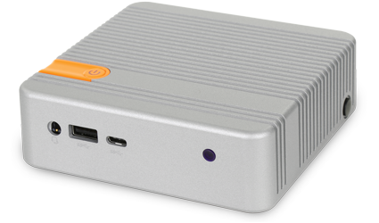
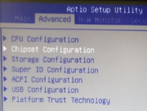
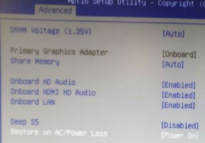

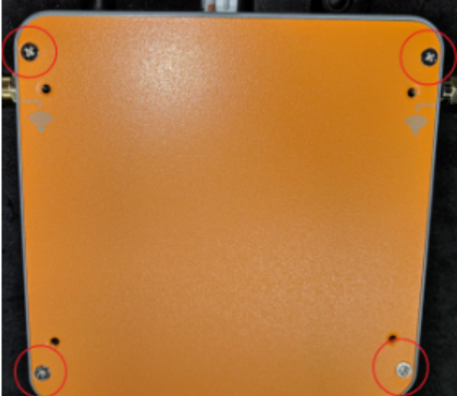
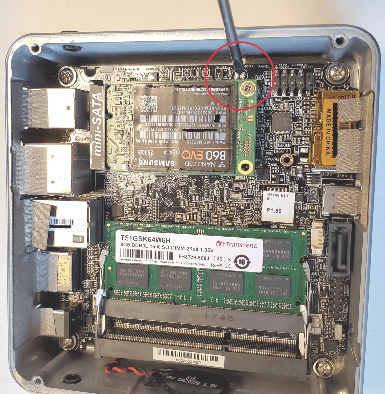
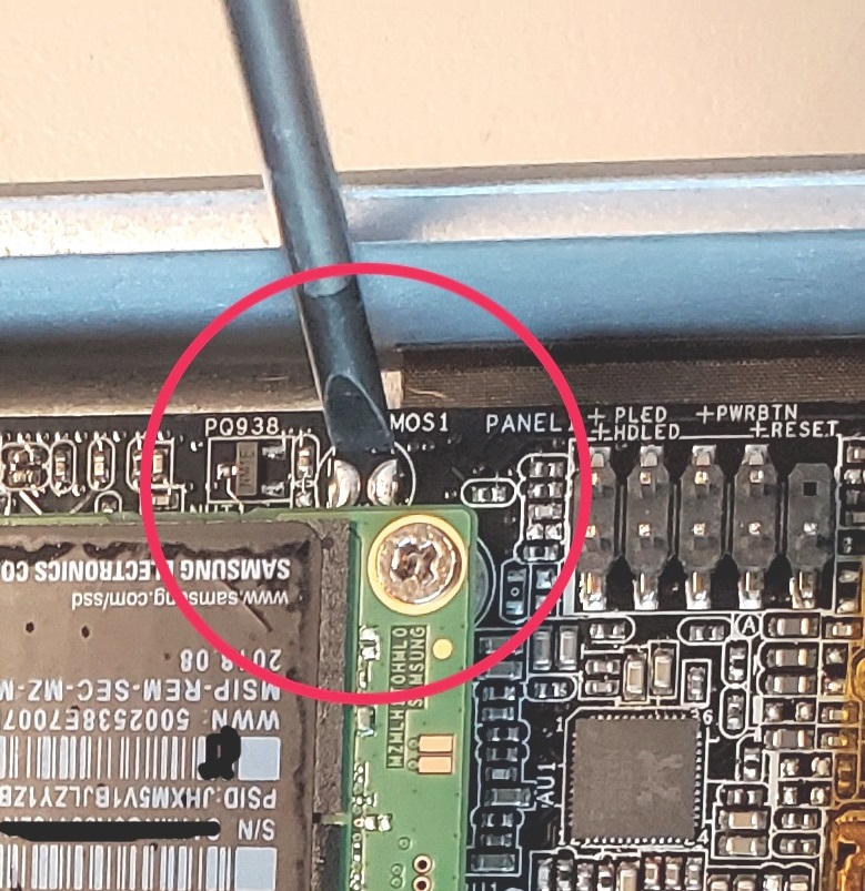
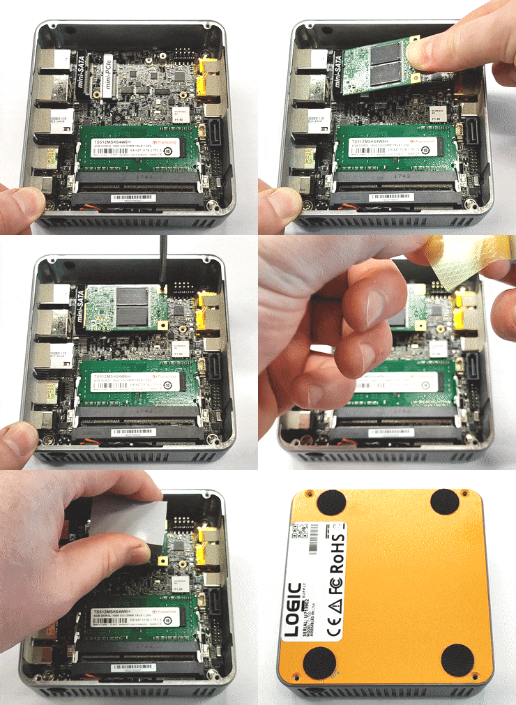
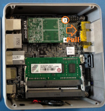
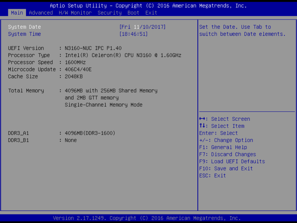
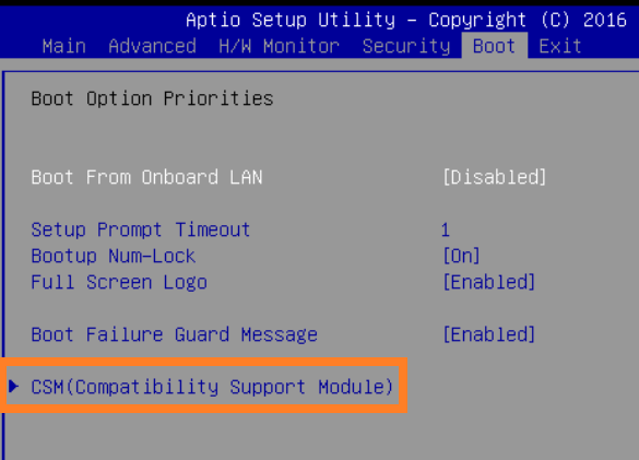
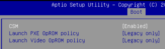
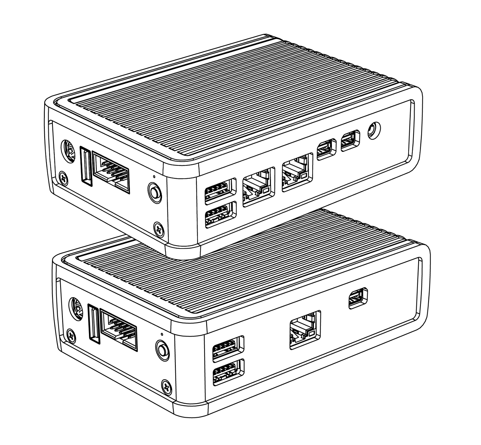

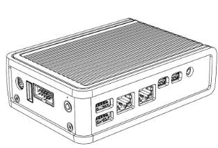
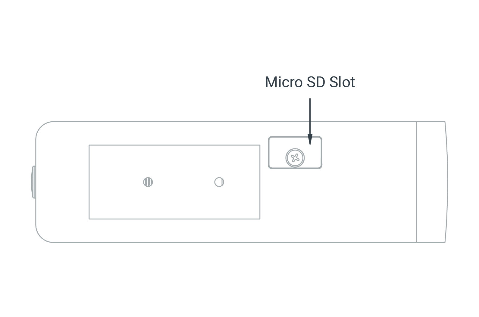
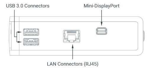
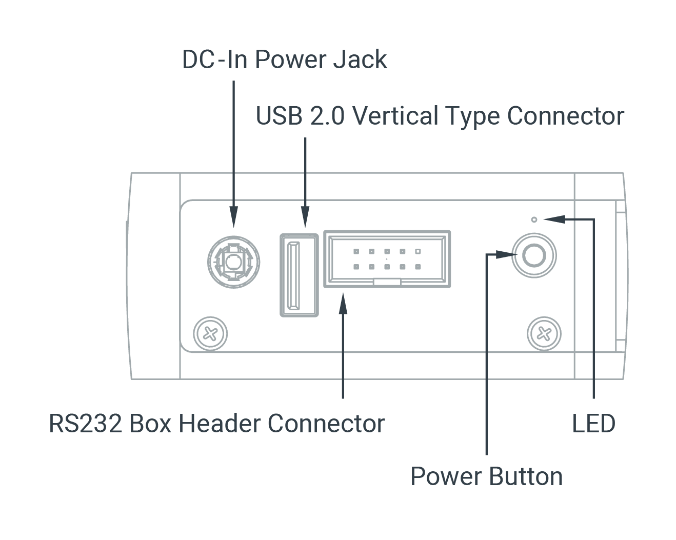
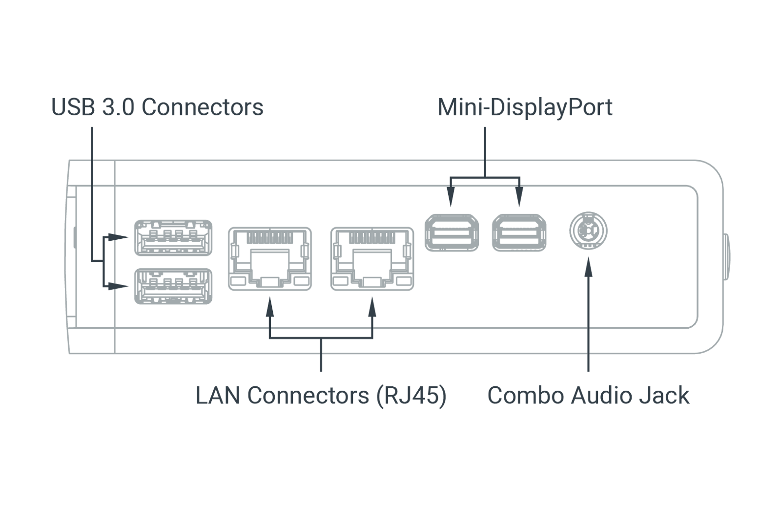

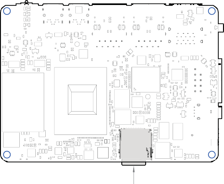
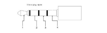

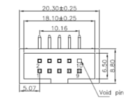

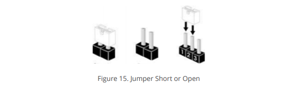
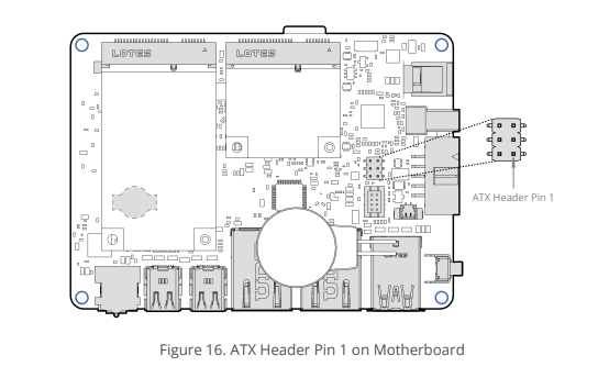
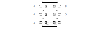



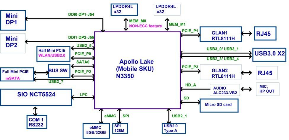
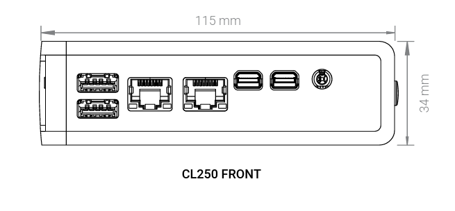


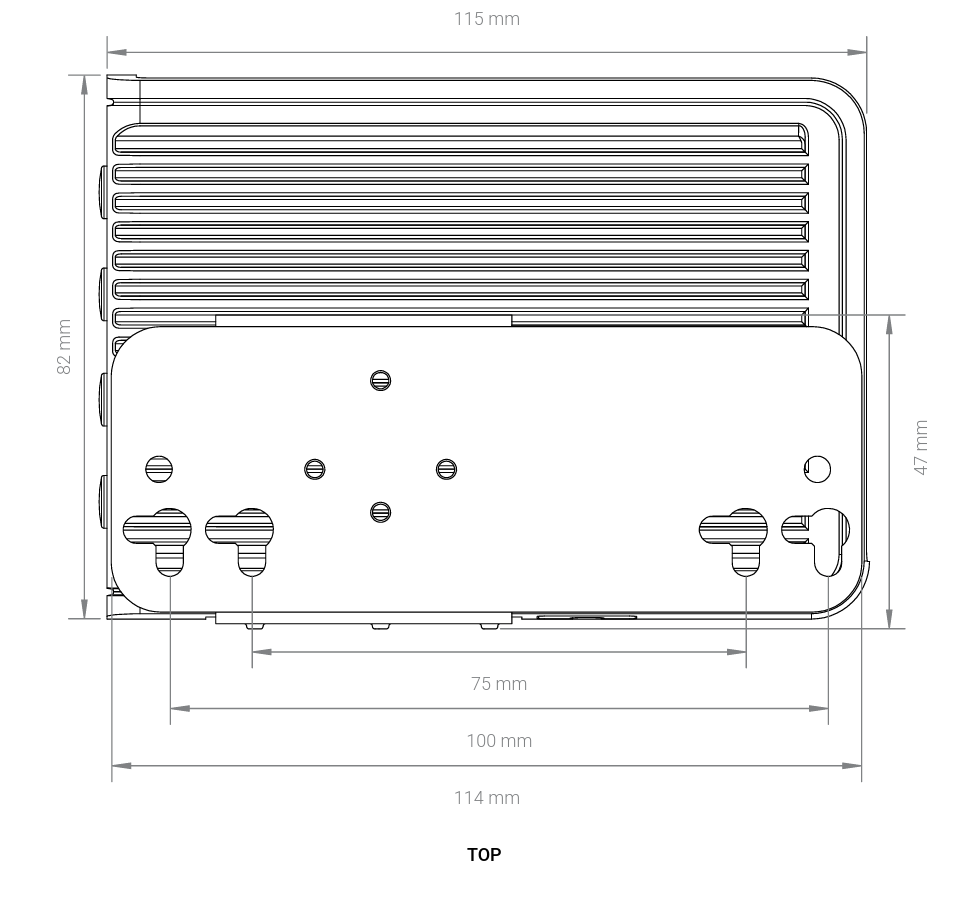
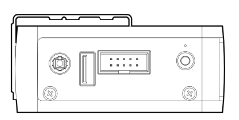

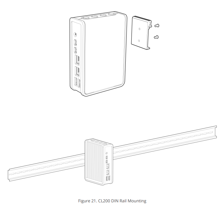

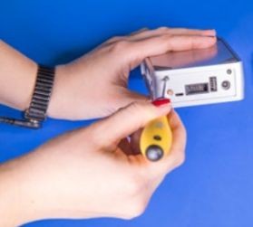
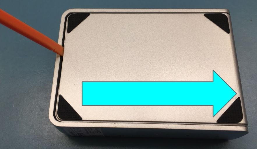


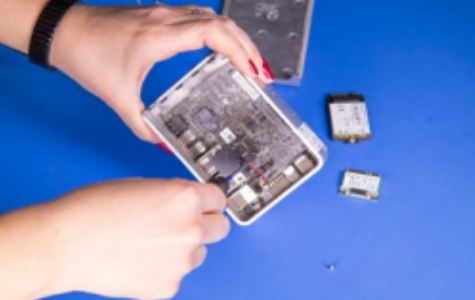
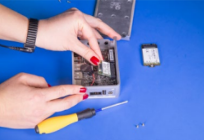


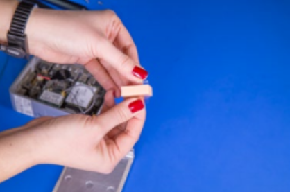
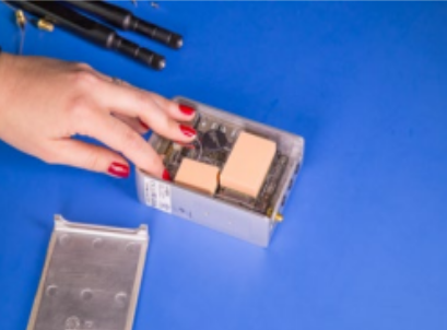
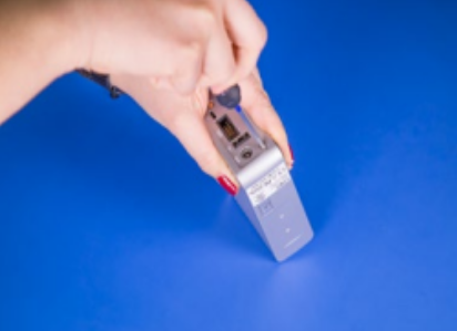

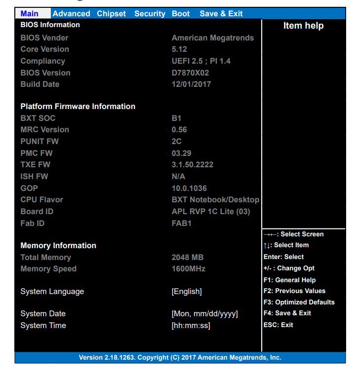
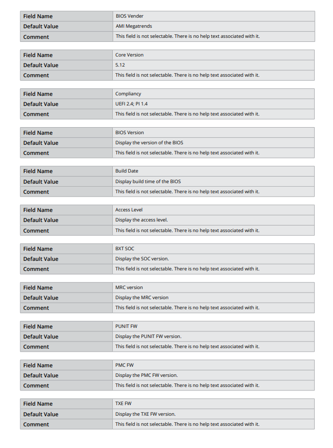
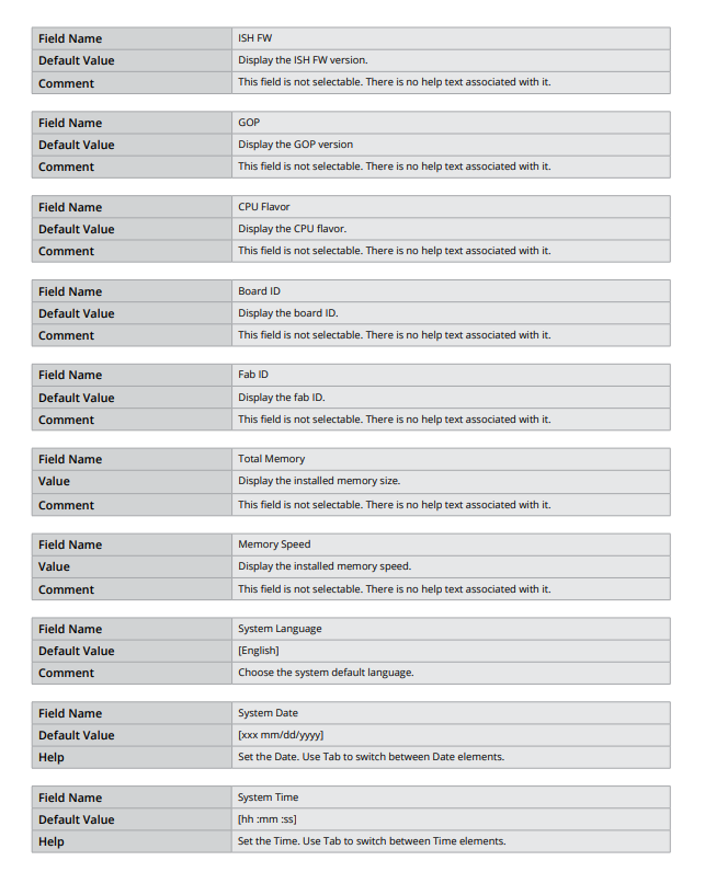
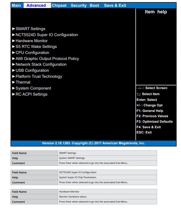
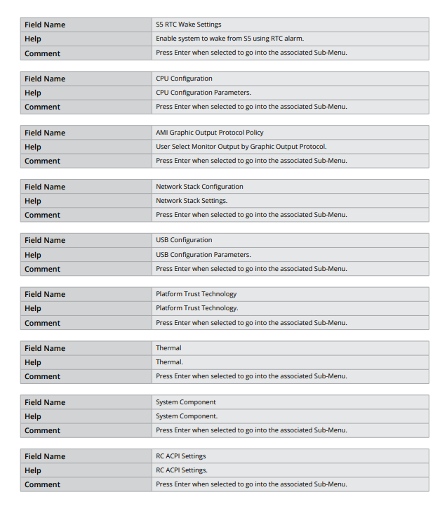
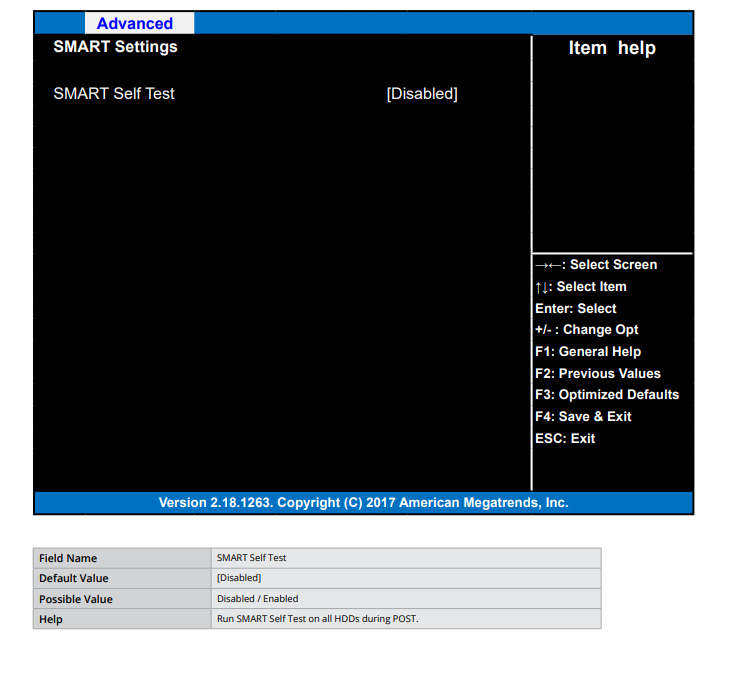
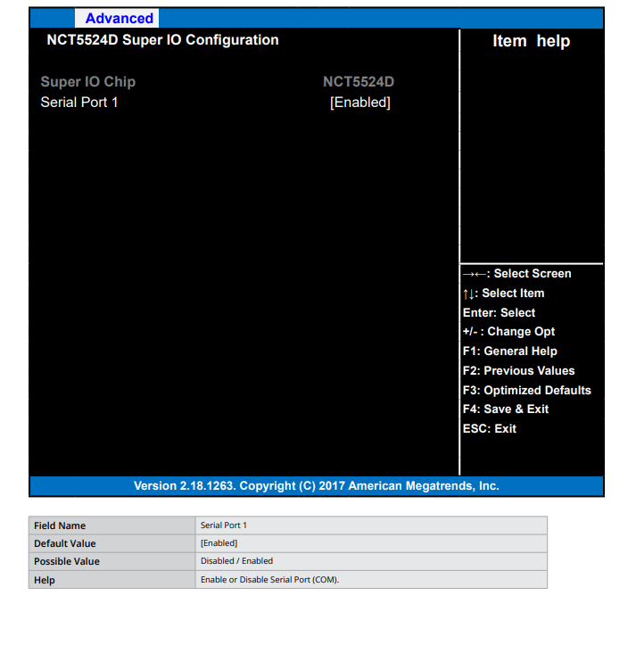
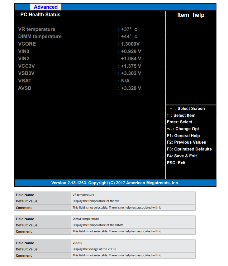
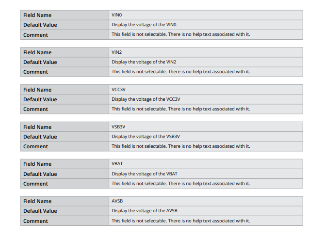
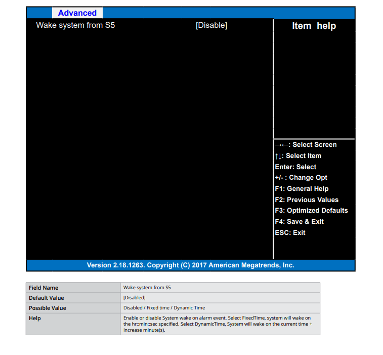
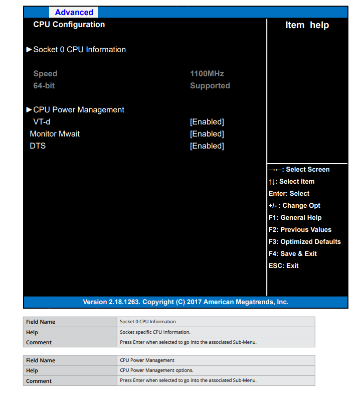
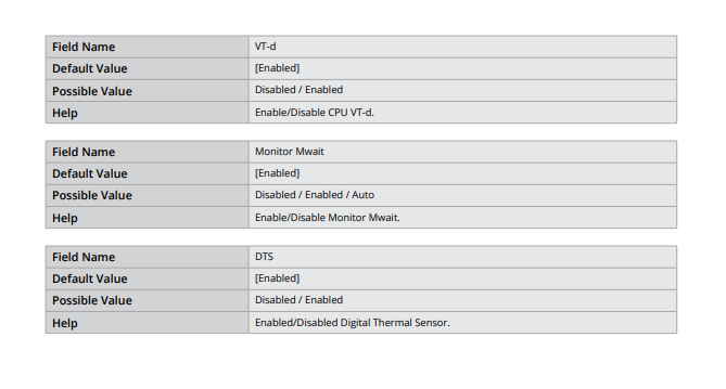
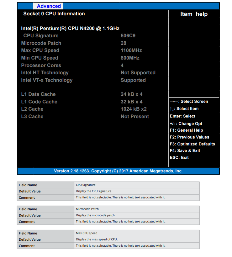
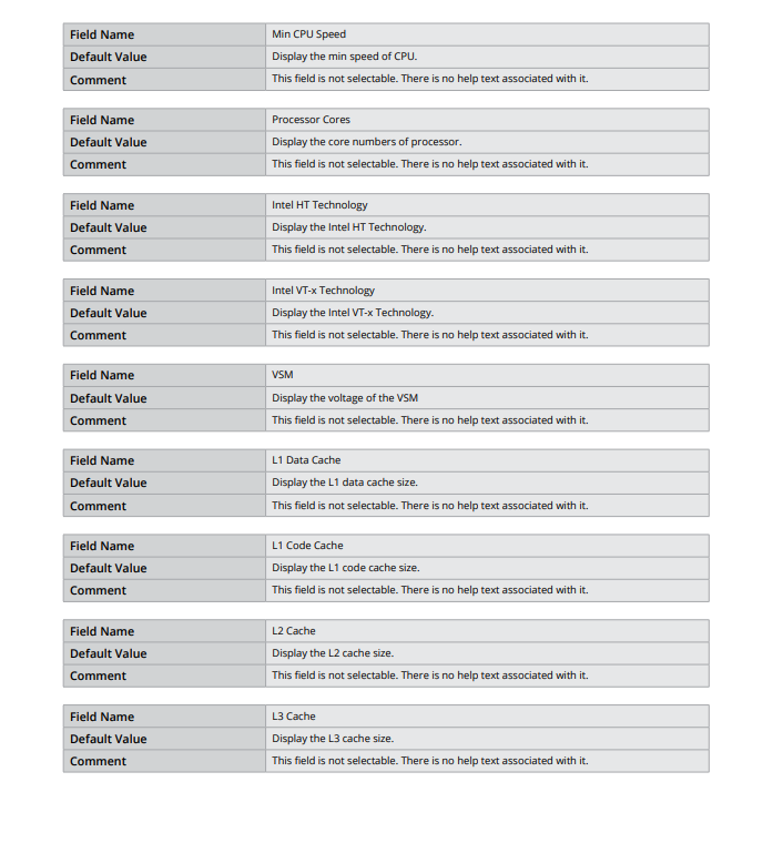
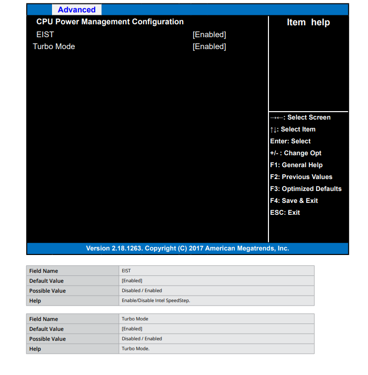
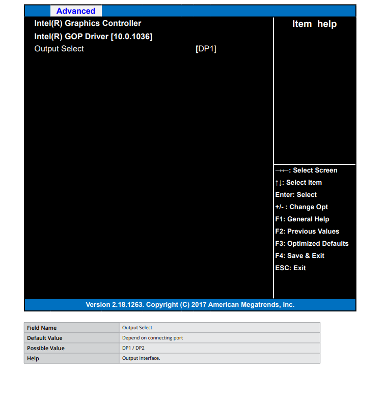
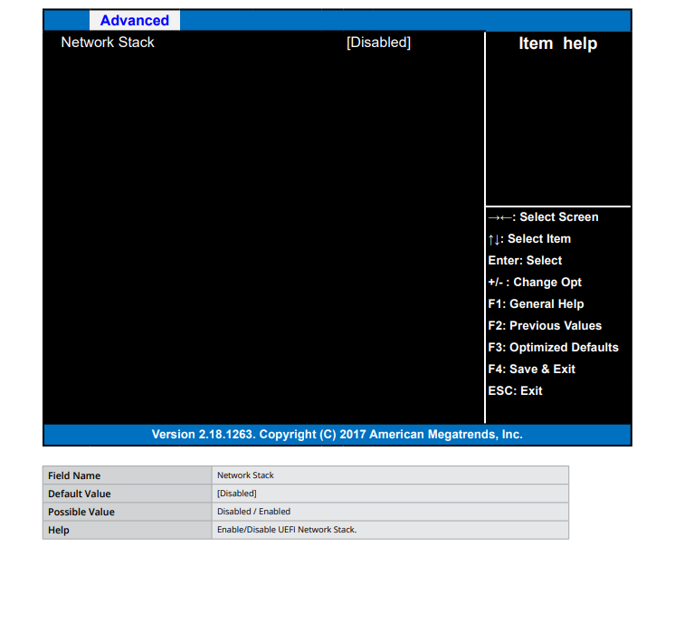
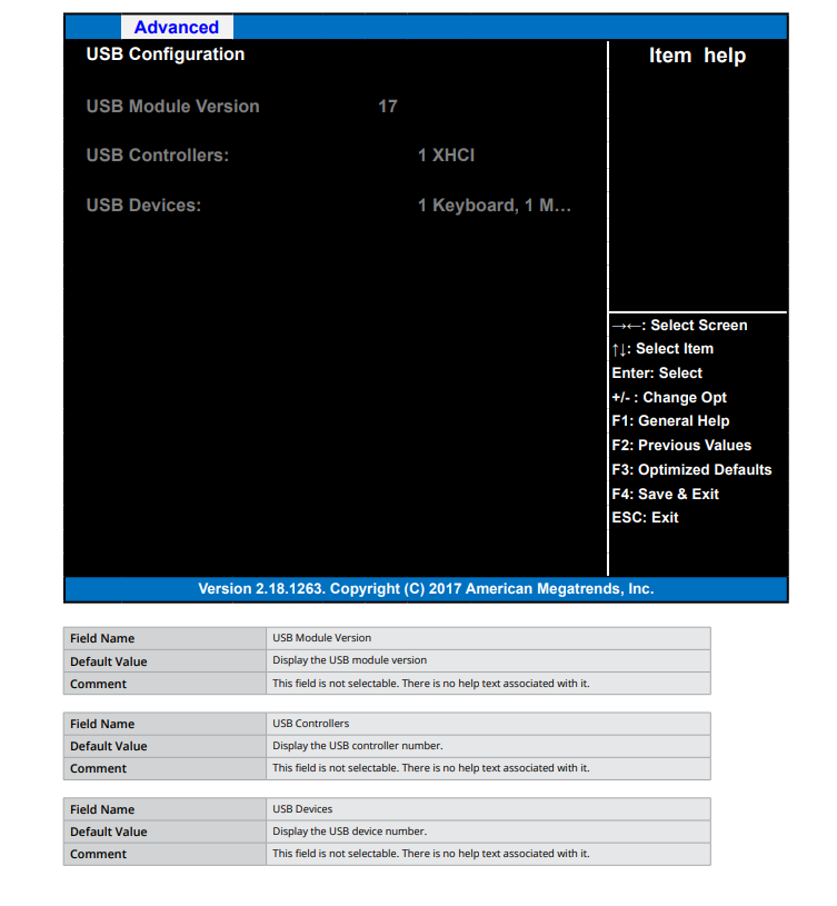
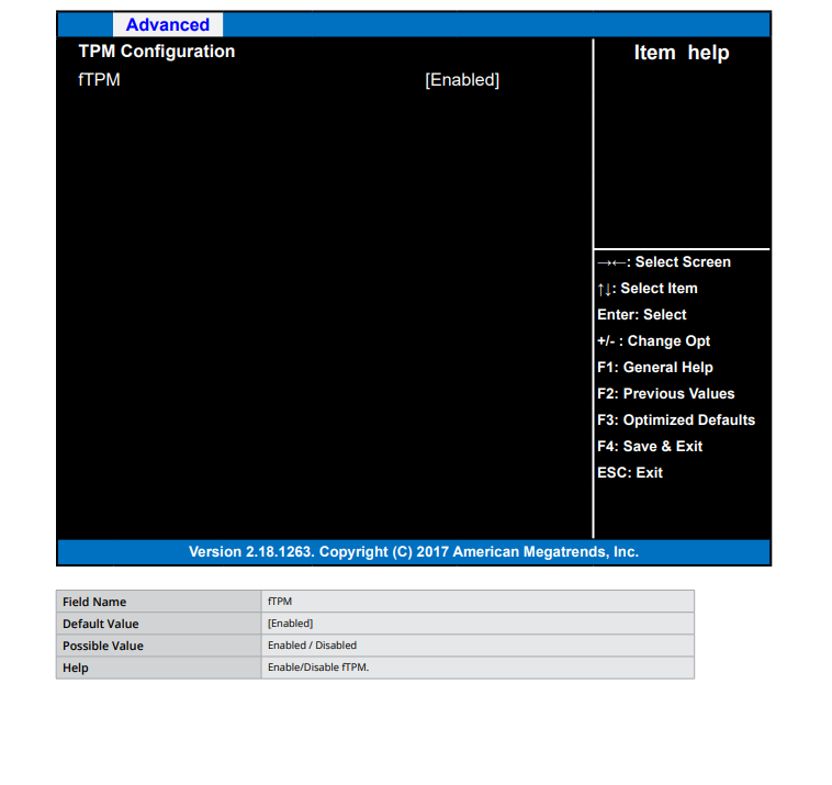
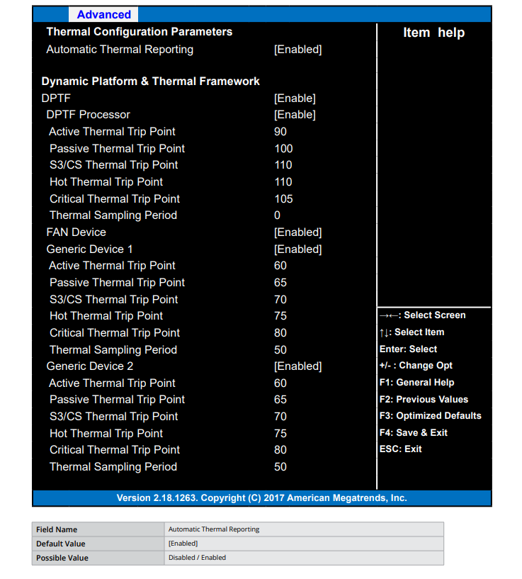
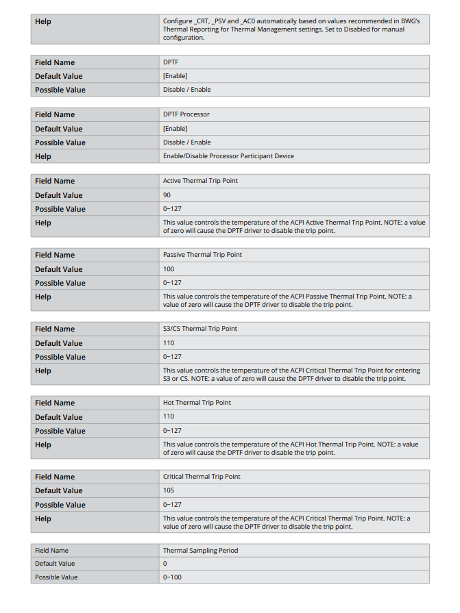
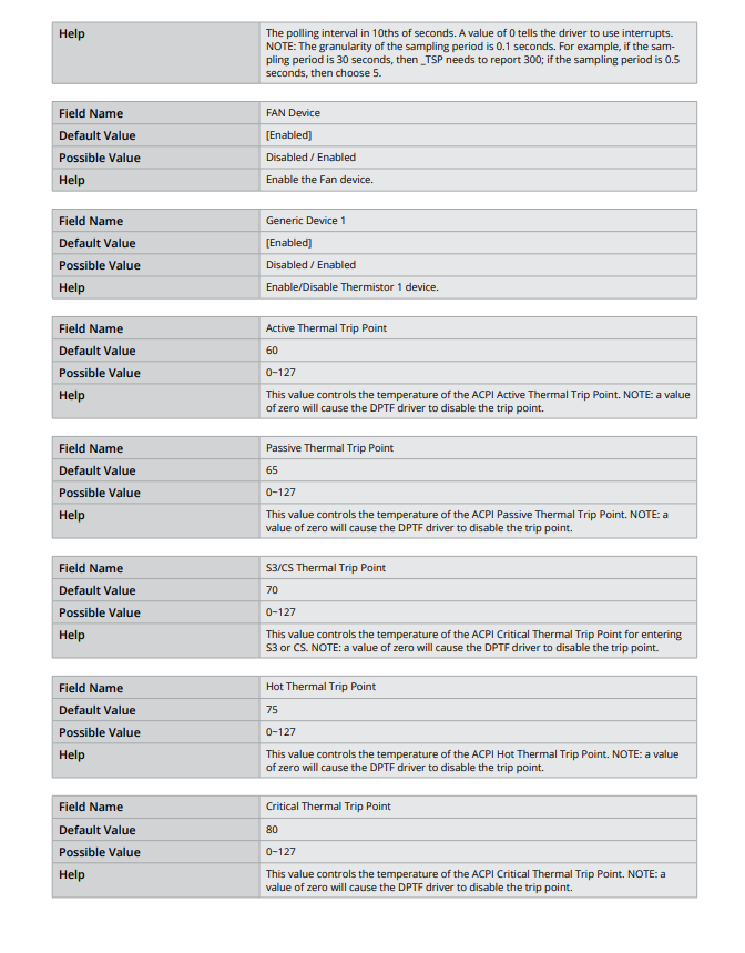
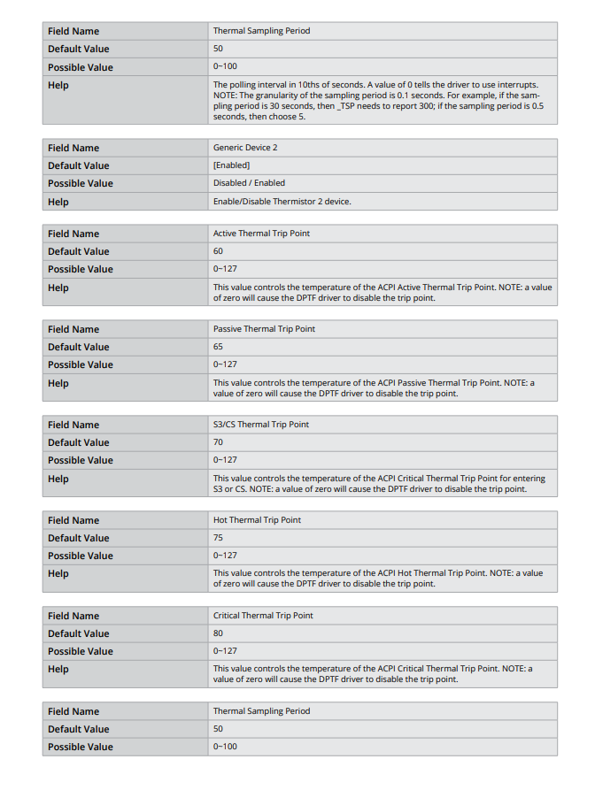
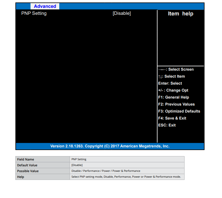
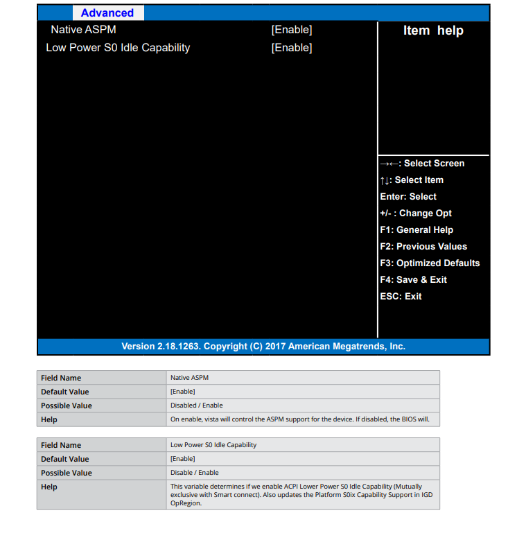
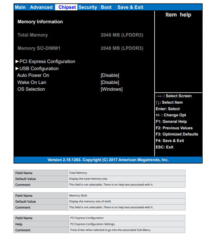
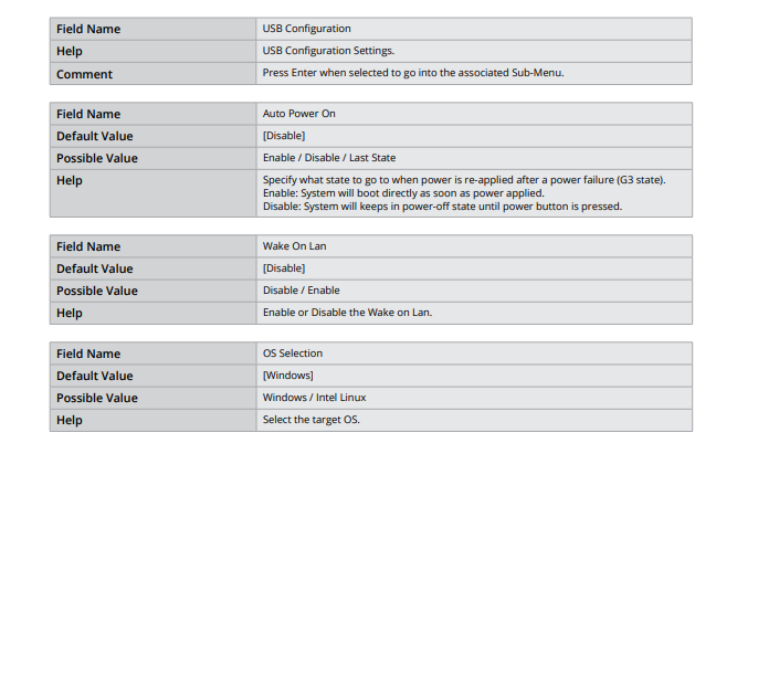
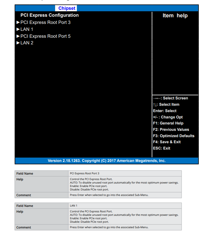
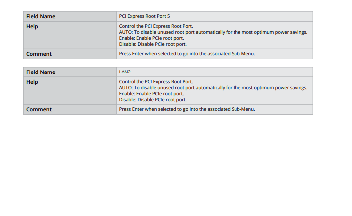
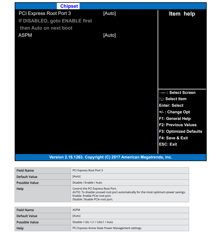
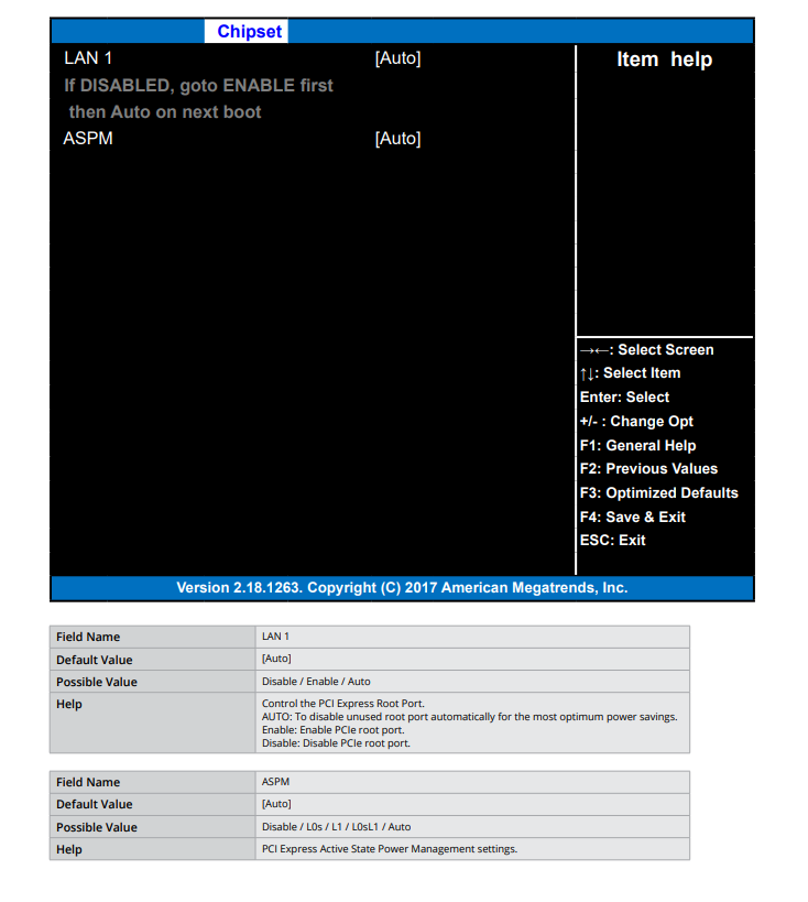
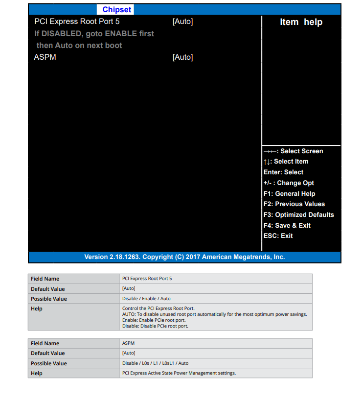
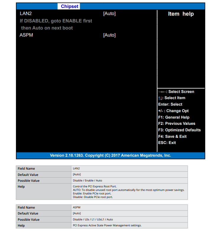
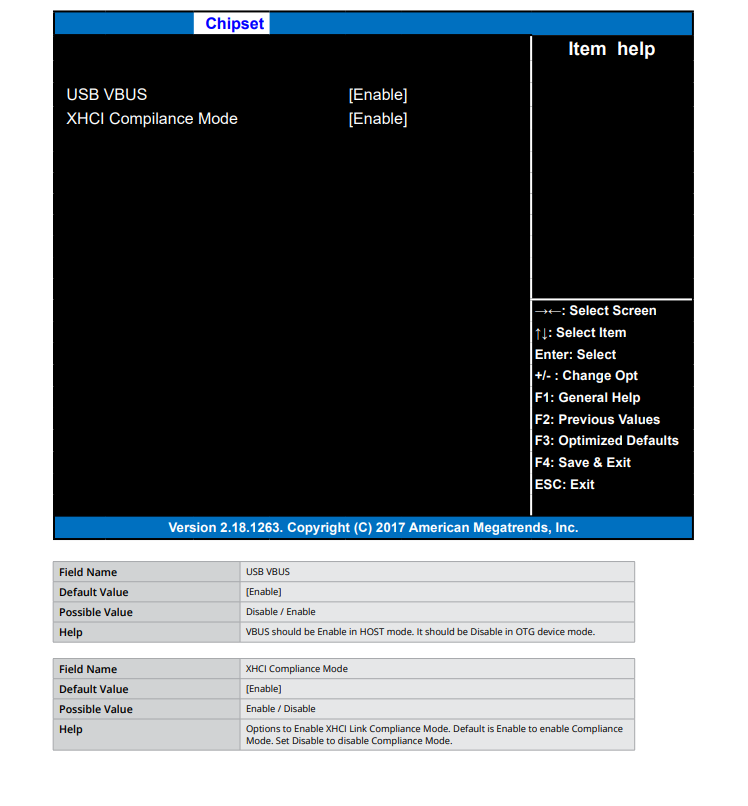
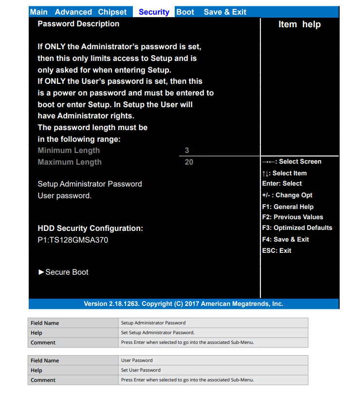
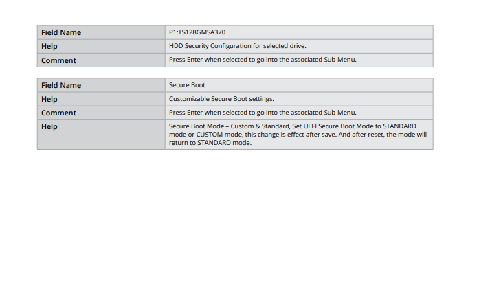
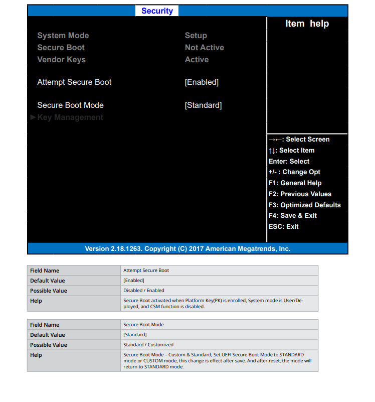
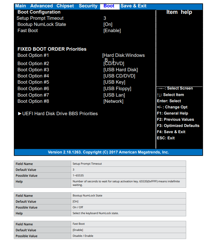
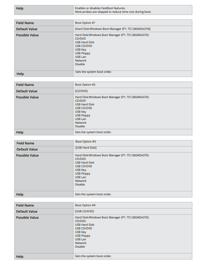
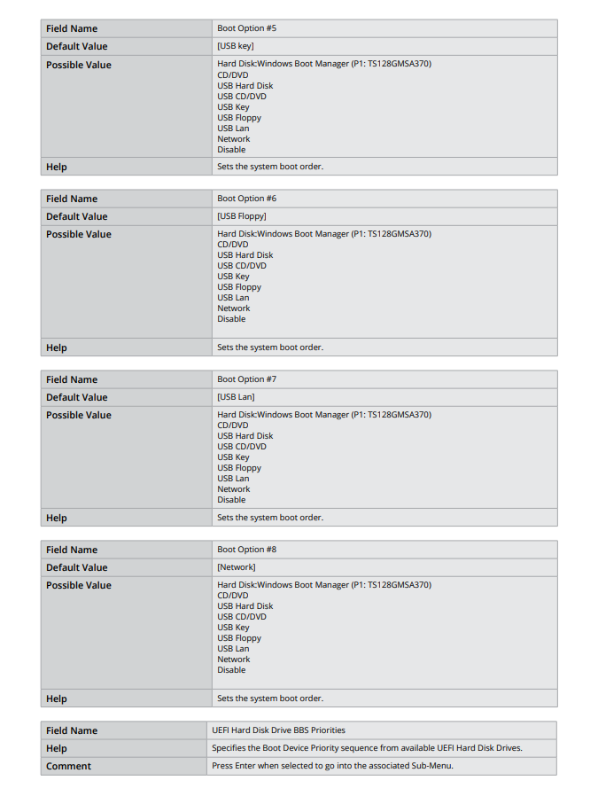
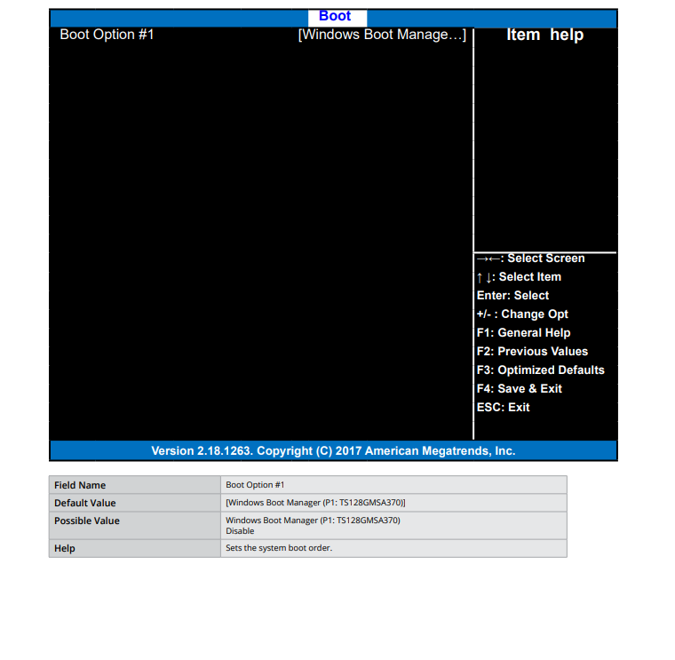


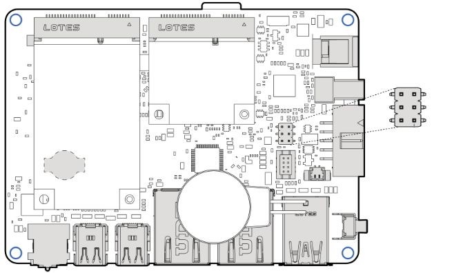
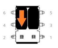
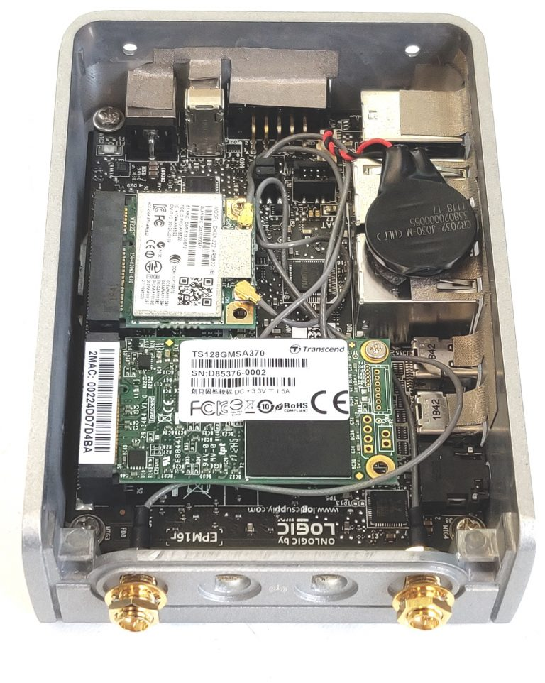


 **Caution, Hot Surface!** It is normal for the unit to heat up and be hot to touch. **Do not touch** the heatsink area or enclosure during operation and 30 minutes after shutdown allowing the unit to cool down.
7. Ambient operating temperature must be between 0 °C to 50 °C with a non-condensing relative humidity of 10-85%.
8. The device can be stored at temperatures between -10 °C to 85 °C. Note: Unit must be stabilized within operating temperature before use, minimum 3HR.
9. Keep the device away from liquids and flammable materials. Not to be installed in a hazardous environment.
10. Do not clean the device with liquids. The chassis can be cleaned with a dry cloth or duster only. To prevent injury to self and/or damage to the device the unit must be powered down and all connecting power and other peripherals shall be disconnected prior to cleaning.
11. Allow adequate space around all sides of the device for proper cooling and to not exceed its maximum operating temperature limit. If the device is mounted to a vertical surface then recommended device orientation is such that heatsink fins allow air to rise unobstructed. Alternative orientations may result in reduced operational temperature range.
12. This device is intended for indoor operation only.
13.
**Caution, Hot Surface!** It is normal for the unit to heat up and be hot to touch. **Do not touch** the heatsink area or enclosure during operation and 30 minutes after shutdown allowing the unit to cool down.
7. Ambient operating temperature must be between 0 °C to 50 °C with a non-condensing relative humidity of 10-85%.
8. The device can be stored at temperatures between -10 °C to 85 °C. Note: Unit must be stabilized within operating temperature before use, minimum 3HR.
9. Keep the device away from liquids and flammable materials. Not to be installed in a hazardous environment.
10. Do not clean the device with liquids. The chassis can be cleaned with a dry cloth or duster only. To prevent injury to self and/or damage to the device the unit must be powered down and all connecting power and other peripherals shall be disconnected prior to cleaning.
11. Allow adequate space around all sides of the device for proper cooling and to not exceed its maximum operating temperature limit. If the device is mounted to a vertical surface then recommended device orientation is such that heatsink fins allow air to rise unobstructed. Alternative orientations may result in reduced operational temperature range.
12. This device is intended for indoor operation only.
13.  **Attention surface chaude!** Il est normal que l'appareil chauffe et soit chaud au toucher. Ne touchez pas la zone du dissipateur thermique ou le boîtier pendant le fonctionnement et 30 minutes après l'arrêt pour permettre à l'unité de refroidir.
8. La température ambiante de fonctionnement doit être comprise entre 0 °C et 40 °C avec une humidité relative sans condensation de 10 à 85 %.
9. L'appareil peut être stocké à des températures comprises entre -10 °C et 85 °C. Remarque : L'unité doit être stabilisée à la température de fonctionnement avant utilisation, minimum 3 heures.
10. Gardez l'appareil à l'écart des liquides et des matériaux inflammables. Ne pas installer dans un environnement dangereux.
11. Ne nettoyez pas l'appareil avec des liquides. Le châssis peut être nettoyé uniquement avec un chiffon sec ou un plumeau. Pour éviter de se blesser et/ou d'endommager l'appareil, l'appareil doit être éteint et toutes les alimentations et autres périphériques doivent être déconnectés avant le nettoyage.
12. Prévoyez un espace suffisant autour de tous les côtés de l'appareil pour un refroidissement correct et pour ne pas dépasser sa limite de température de fonctionnement maximale. Si l'appareil est monté sur une surface verticale, l'orientation recommandée de l'appareil est telle que les ailettes du dissipateur thermique permettent à l'air de monter sans obstruction. Des orientations alternatives peuvent entraîner une plage de températures de fonctionnement réduite.
13. Cet appareil est destiné à une utilisation en intérieur uniquement.
14.
**Attention surface chaude!** Il est normal que l'appareil chauffe et soit chaud au toucher. Ne touchez pas la zone du dissipateur thermique ou le boîtier pendant le fonctionnement et 30 minutes après l'arrêt pour permettre à l'unité de refroidir.
8. La température ambiante de fonctionnement doit être comprise entre 0 °C et 40 °C avec une humidité relative sans condensation de 10 à 85 %.
9. L'appareil peut être stocké à des températures comprises entre -10 °C et 85 °C. Remarque : L'unité doit être stabilisée à la température de fonctionnement avant utilisation, minimum 3 heures.
10. Gardez l'appareil à l'écart des liquides et des matériaux inflammables. Ne pas installer dans un environnement dangereux.
11. Ne nettoyez pas l'appareil avec des liquides. Le châssis peut être nettoyé uniquement avec un chiffon sec ou un plumeau. Pour éviter de se blesser et/ou d'endommager l'appareil, l'appareil doit être éteint et toutes les alimentations et autres périphériques doivent être déconnectés avant le nettoyage.
12. Prévoyez un espace suffisant autour de tous les côtés de l'appareil pour un refroidissement correct et pour ne pas dépasser sa limite de température de fonctionnement maximale. Si l'appareil est monté sur une surface verticale, l'orientation recommandée de l'appareil est telle que les ailettes du dissipateur thermique permettent à l'air de monter sans obstruction. Des orientations alternatives peuvent entraîner une plage de températures de fonctionnement réduite.
13. Cet appareil est destiné à une utilisation en intérieur uniquement.
14. 
 ### 2.2- I/O Definitions
#### Front I/O Definition
### 2.2- I/O Definitions
#### Front I/O Definition


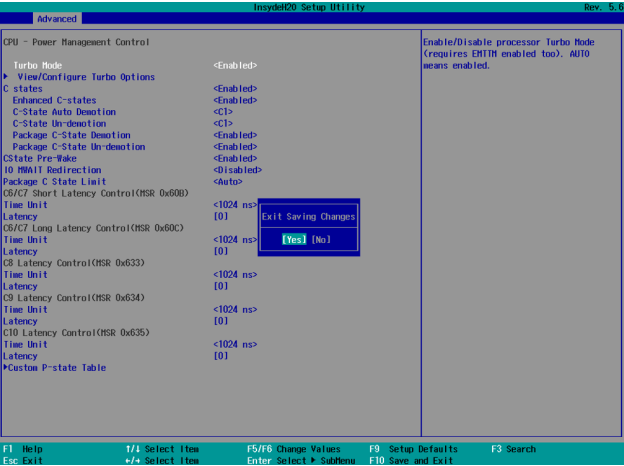


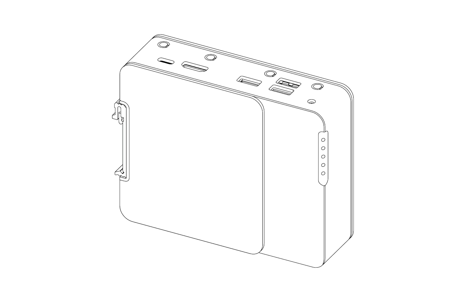
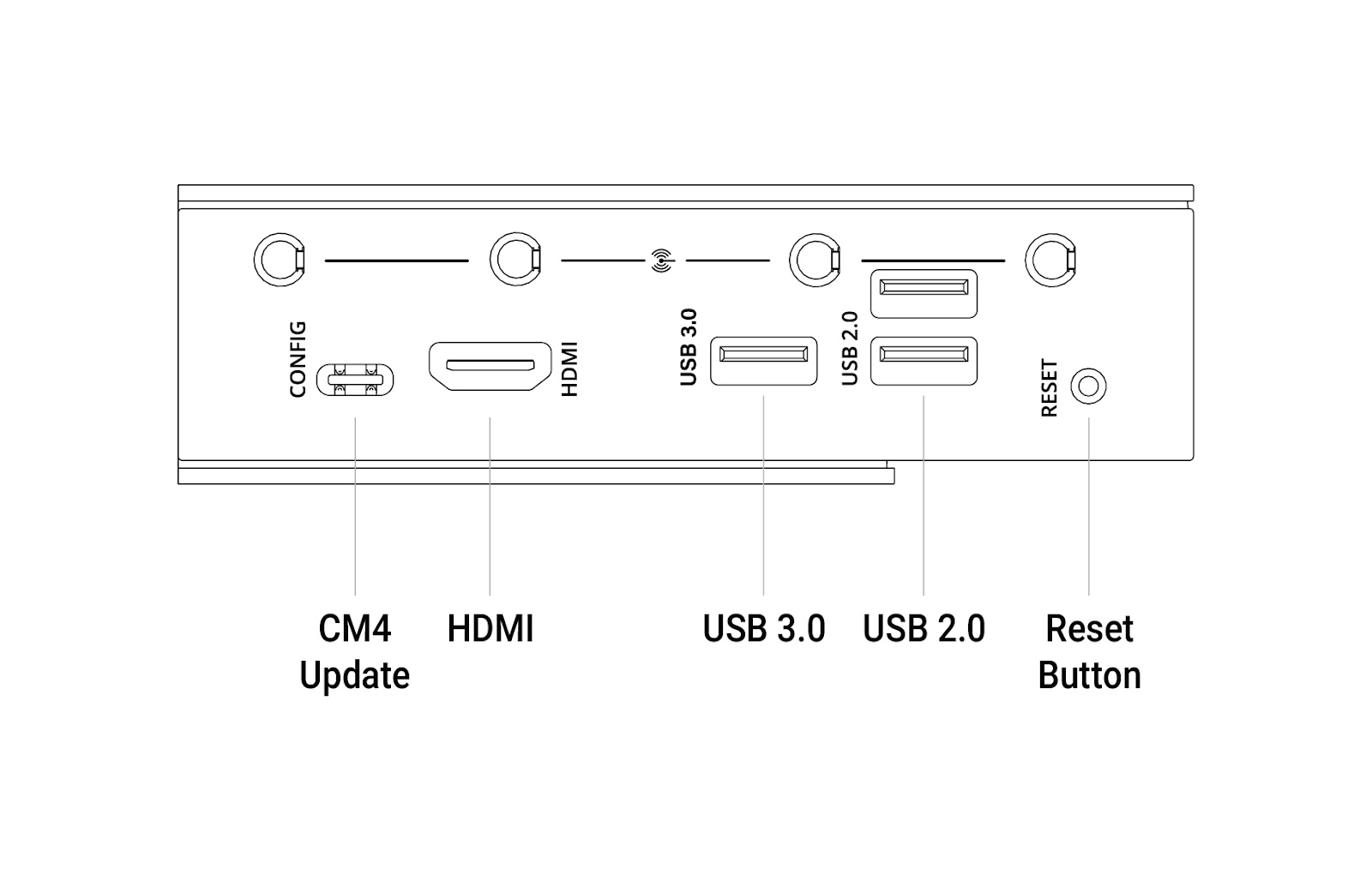
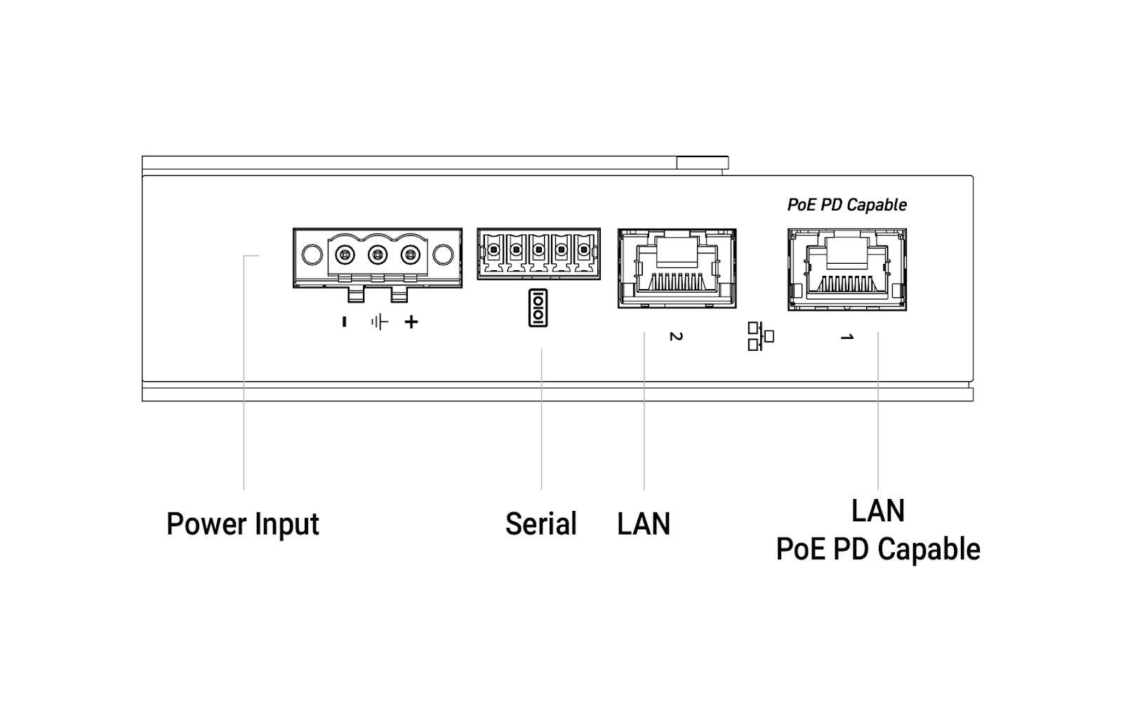


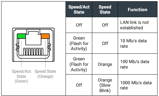


.png?alt=media&token=d87c89cc-31b9-439d-acf5-3d08713a75bd)
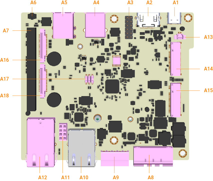


.jpeg?alt=media&token=2896b80c-f01f-4c12-8555-ab347896f421)
.jpeg?alt=media&token=ceadd683-9d9f-4557-aa16-c3a9fe9bd18b)
.jpeg?alt=media&token=726a0d6a-9d5f-4afe-9aff-c8bc81779d54)
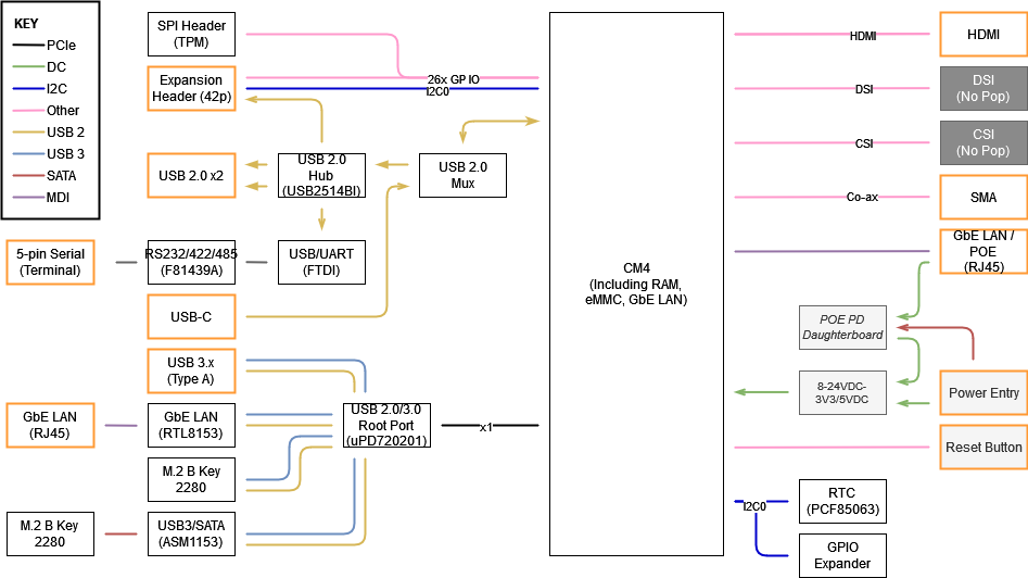
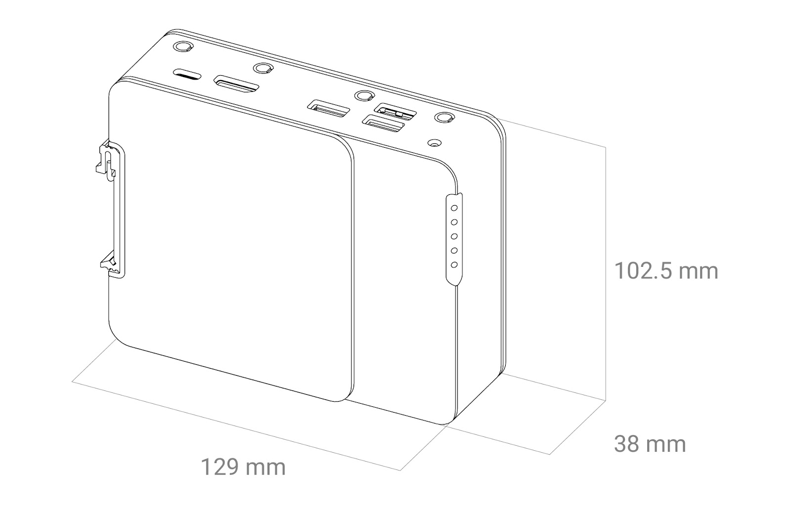



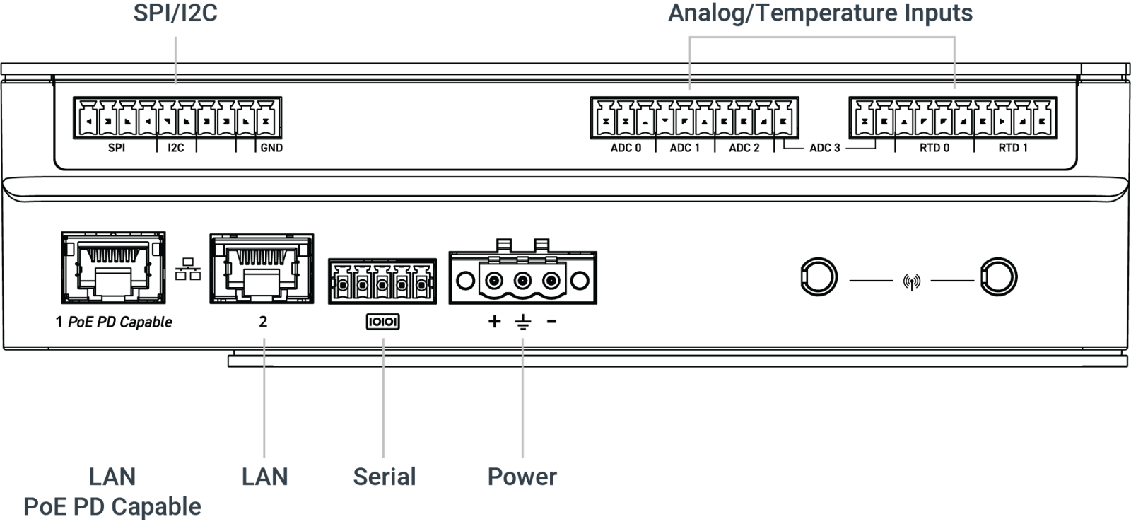
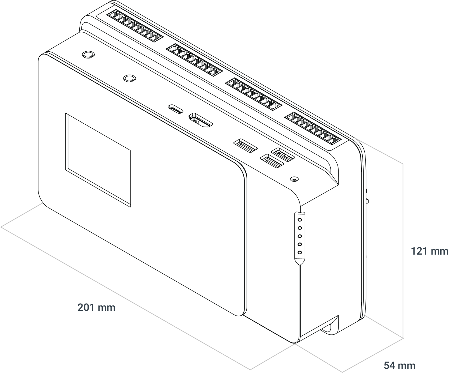
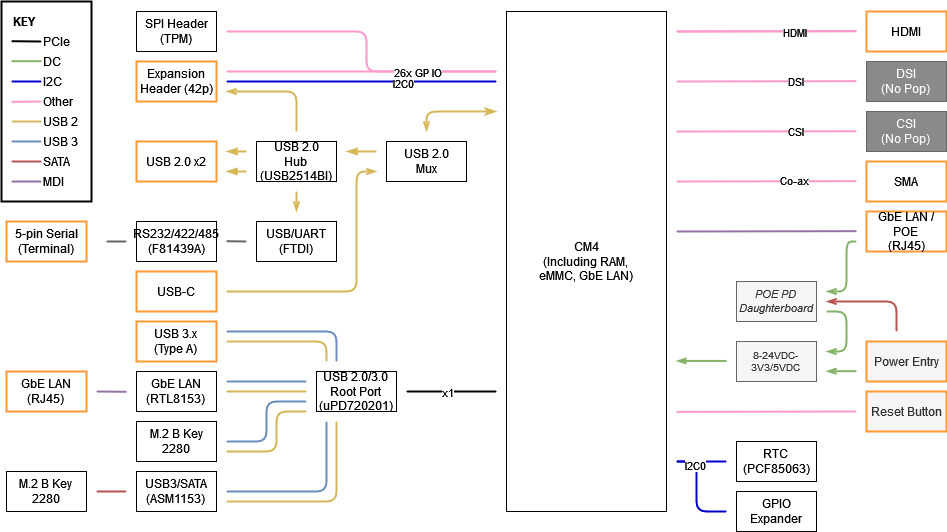
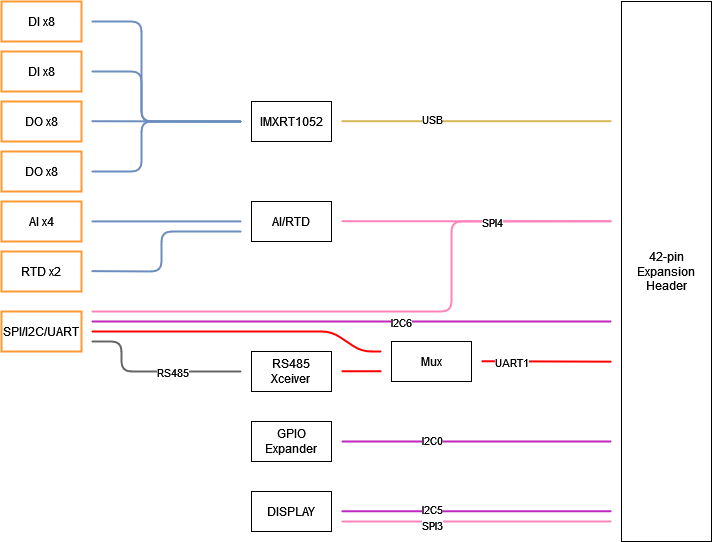


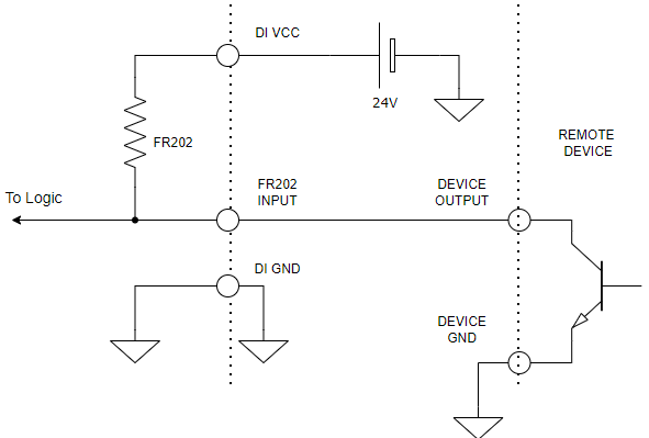
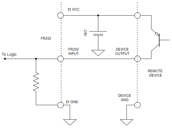

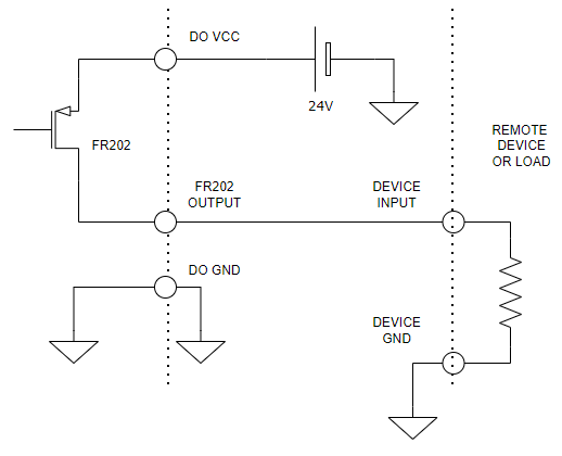
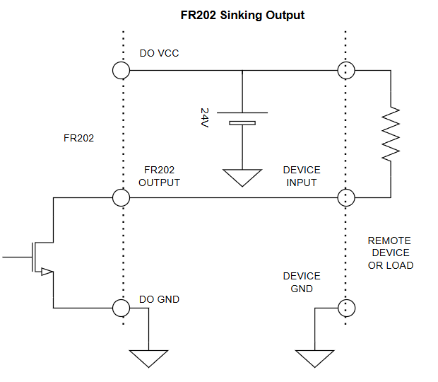


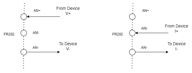
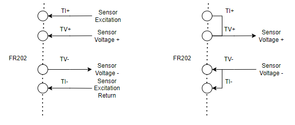
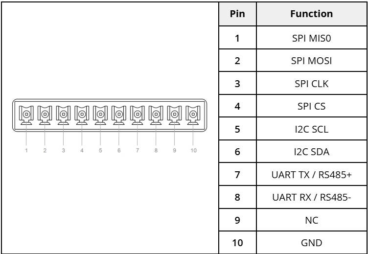
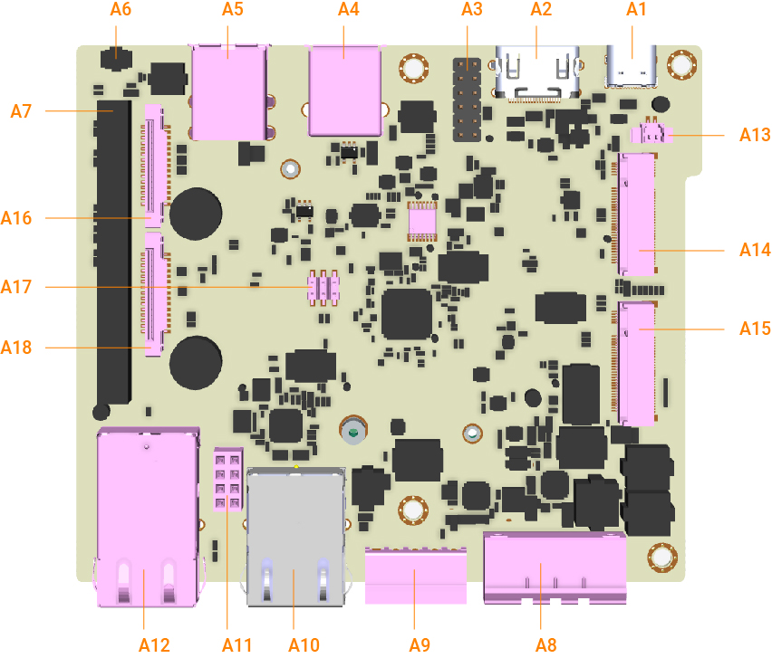



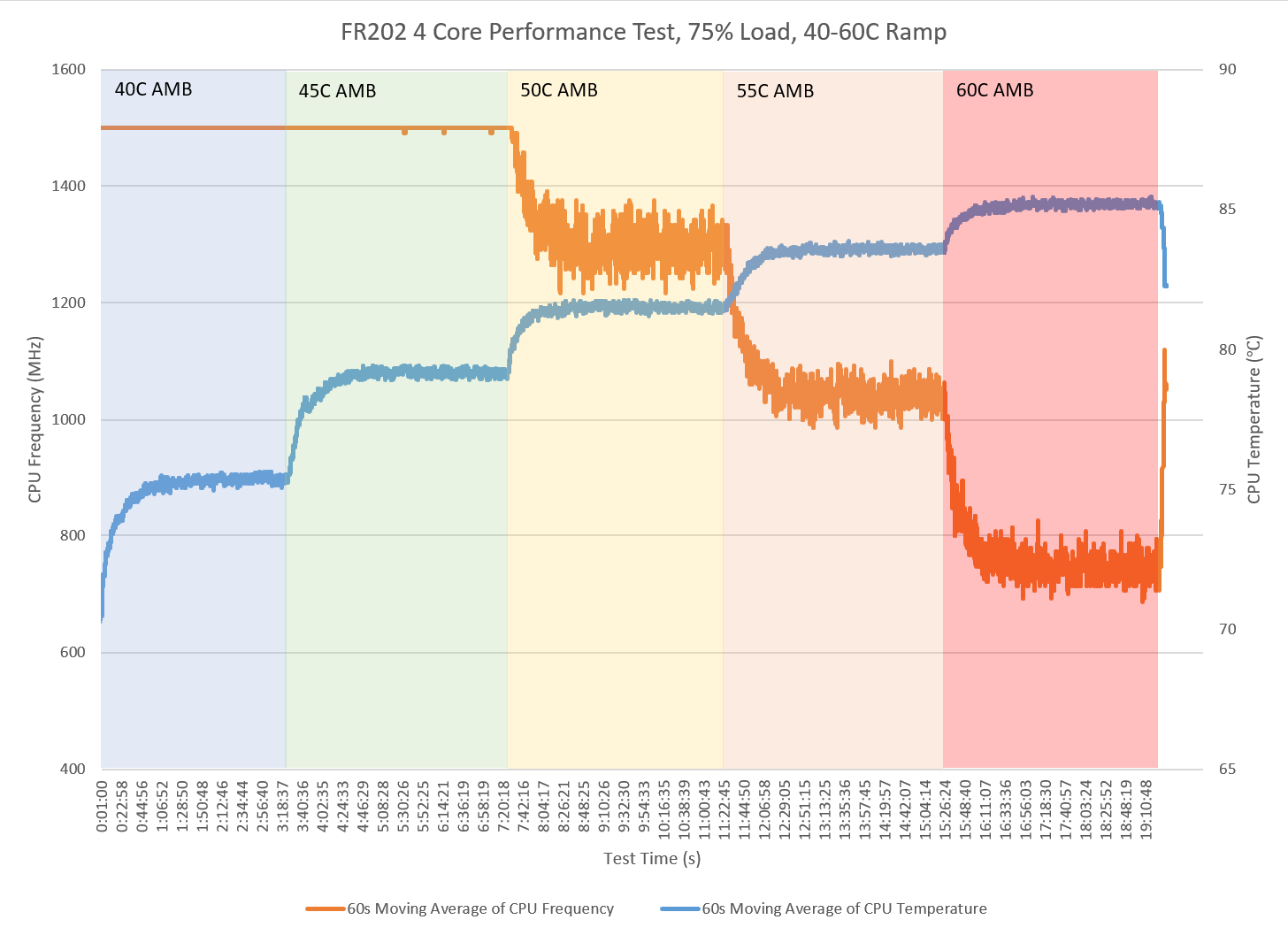
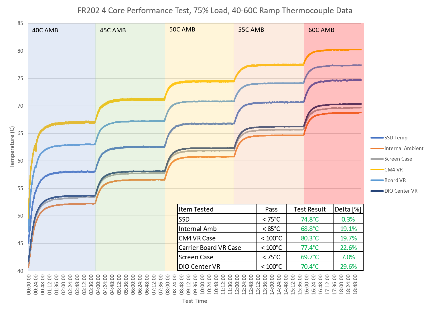

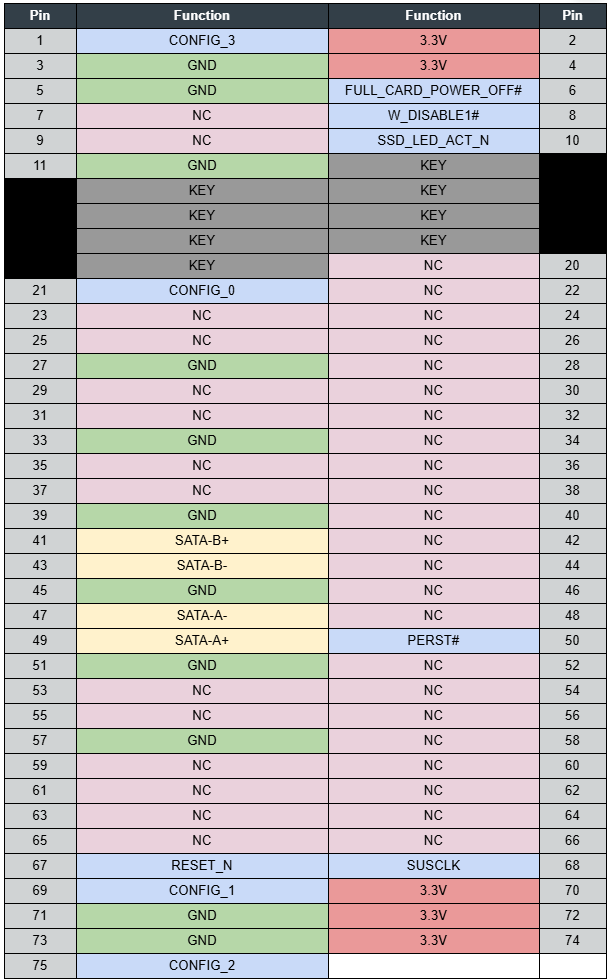


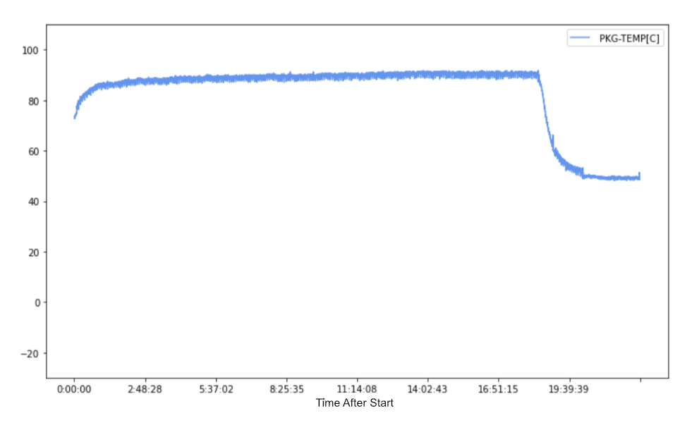
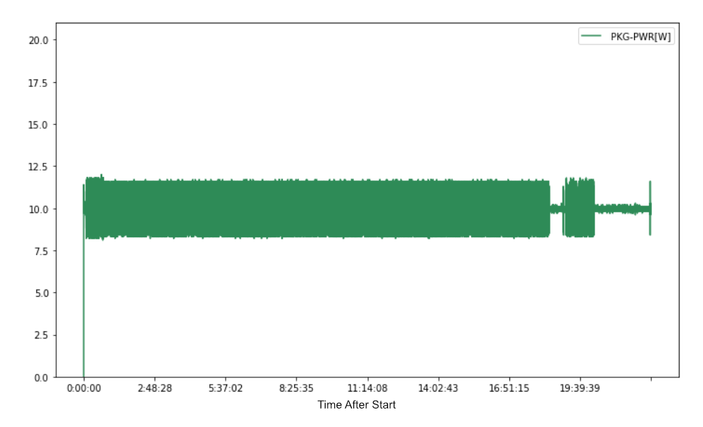
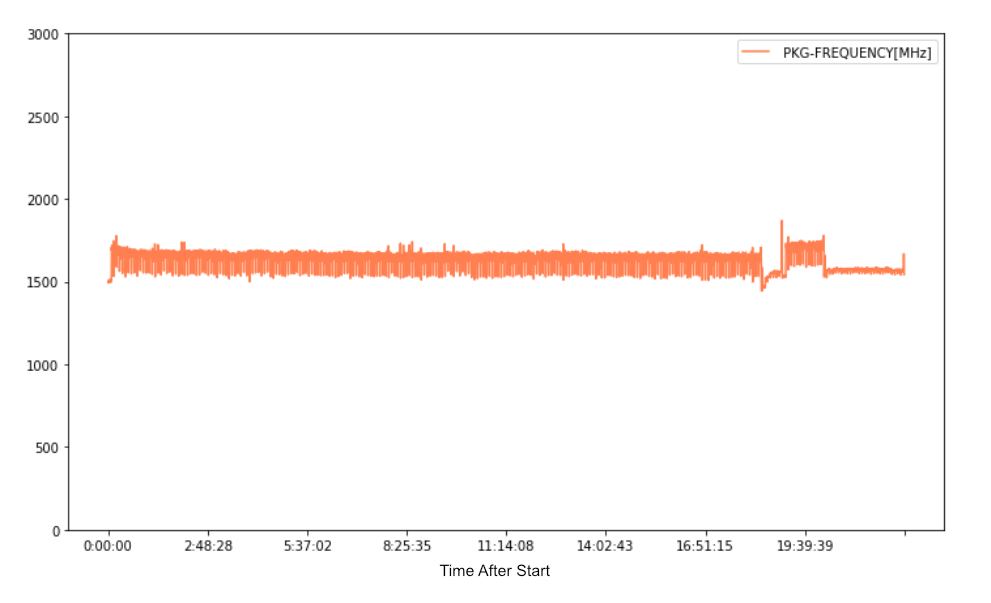


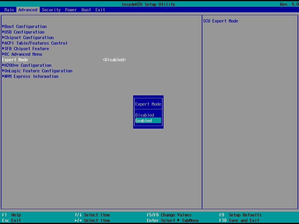
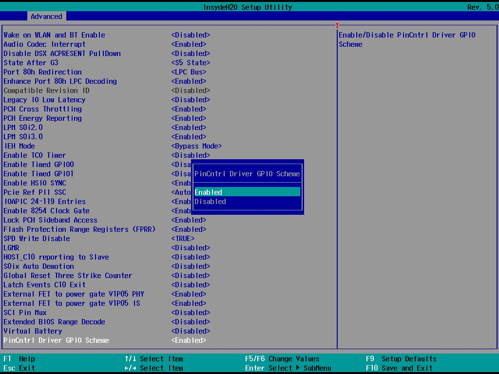

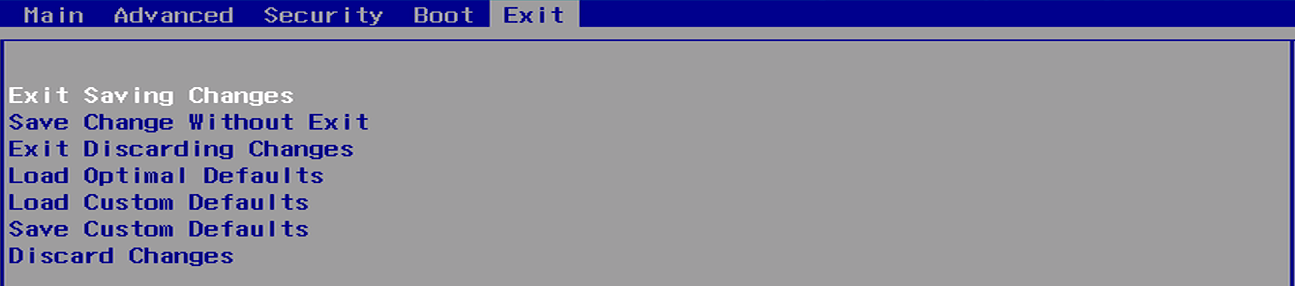
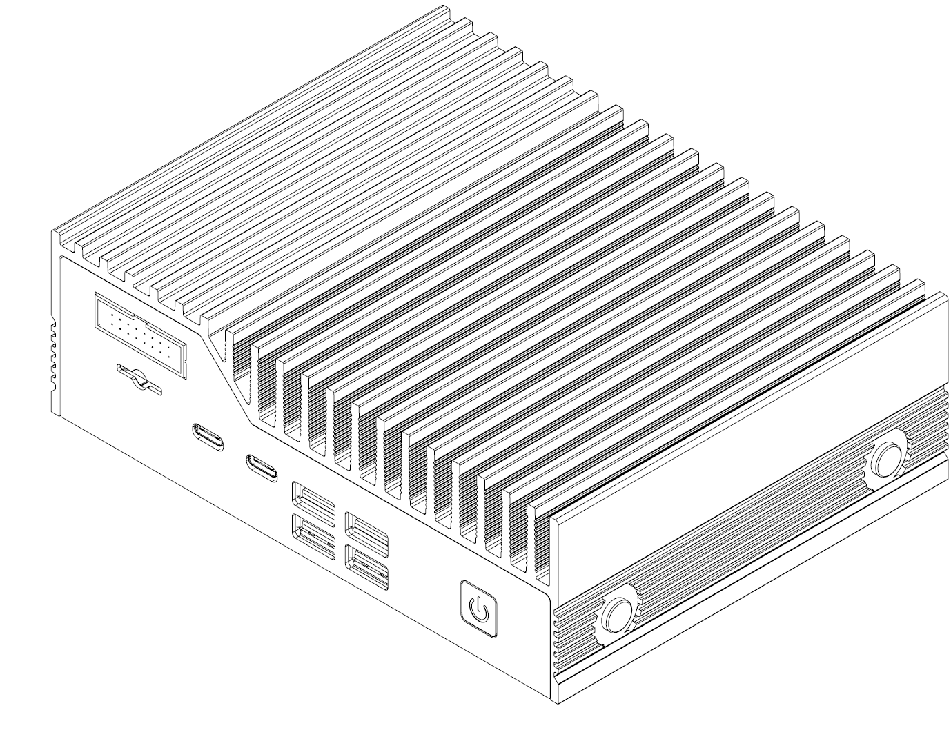


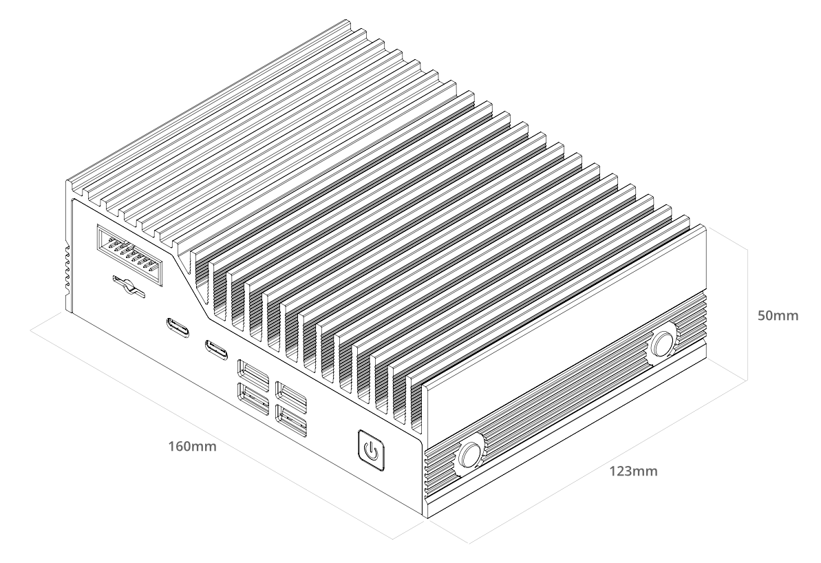


 |
|  | FCC 47 CFR Part 15 Subpart B (Class A) |
|
| FCC 47 CFR Part 15 Subpart B (Class A) |
|  |
|  | RoHS Directive (2011/65/EU, (EU)2015/863) |
|
| RoHS Directive (2011/65/EU, (EU)2015/863) |
|  | WEEE Directive (2012/19/EU) |
|
| WEEE Directive (2012/19/EU) |
|  | IEC60601-1-2, 4th ed. |
|
| IEC60601-1-2, 4th ed. |
|  | EN 60945, 4th ed. |
## 2- Technical Specifications
### 2.0- External Features
#### Front I/O (HX521)
| EN 60945, 4th ed. |
## 2- Technical Specifications
### 2.0- External Features
#### Front I/O (HX521)


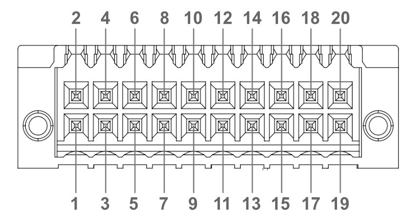


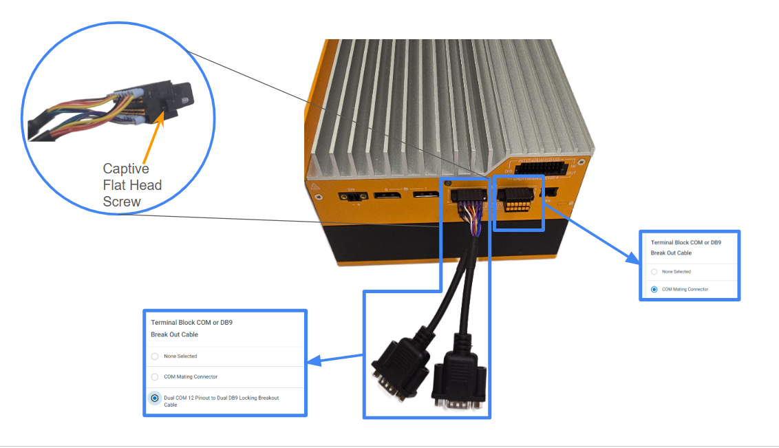


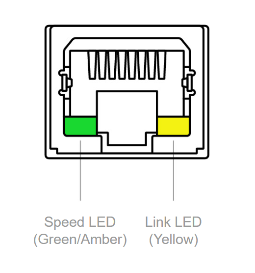


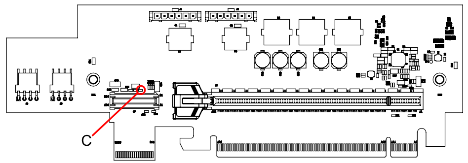


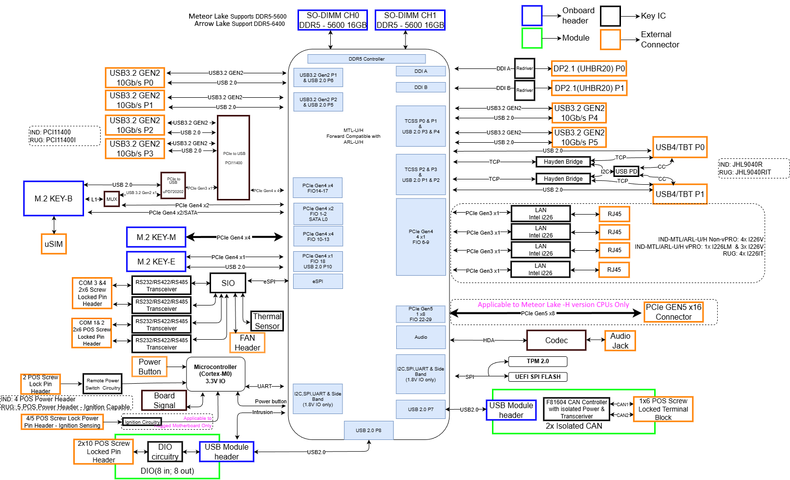


 |
| 
 |
|  |
|  |
|  |
| 


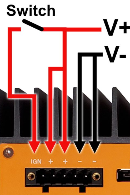 ### 6.2- Enabling and Controlling Ignition Sense
The Karbon 520 Series has three options for controlling automotive settings. The simplest method is to set them through the dedicated BIOS page. The LPMCU command-line tool can also configure automotive settings, provided that the access port in Windows is correctly enabled as described in [Section 3.1.1](#go4nsroj45j7). Additionally, the custom Python package provided in Section 2 can programmatically embed ignition sensing feature control within scripting environments.
**Accessing Automotive Settings** in the BIOS
* Power on the system and repeatedly press the Del to access the BIOS
* Arrow down and choose “Setup Utility” by pressing enter

* Navigate to the Advanced tab and open the Automotive Ignition menu.

* Set Automotive Mode Enabled

* The menu reveals the configurable options that can be set by the user

* Press F10 to save and exit.
**Change Windows Power Button Settings**
* Ignition sensing simulates a power button press. In Windows, the default behavior of the power button press is to put the system into Sleep mode. Change the power button press behavior to “Shut Down” instead.
* Windows “fast startup” will interfere with ignition sensing, so this should be disabled.
### 6.2- Enabling and Controlling Ignition Sense
The Karbon 520 Series has three options for controlling automotive settings. The simplest method is to set them through the dedicated BIOS page. The LPMCU command-line tool can also configure automotive settings, provided that the access port in Windows is correctly enabled as described in [Section 3.1.1](#go4nsroj45j7). Additionally, the custom Python package provided in Section 2 can programmatically embed ignition sensing feature control within scripting environments.
**Accessing Automotive Settings** in the BIOS
* Power on the system and repeatedly press the Del to access the BIOS
* Arrow down and choose “Setup Utility” by pressing enter

* Navigate to the Advanced tab and open the Automotive Ignition menu.

* Set Automotive Mode Enabled

* The menu reveals the configurable options that can be set by the user

* Press F10 to save and exit.
**Change Windows Power Button Settings**
* Ignition sensing simulates a power button press. In Windows, the default behavior of the power button press is to put the system into Sleep mode. Change the power button press behavior to “Shut Down” instead.
* Windows “fast startup” will interfere with ignition sensing, so this should be disabled.
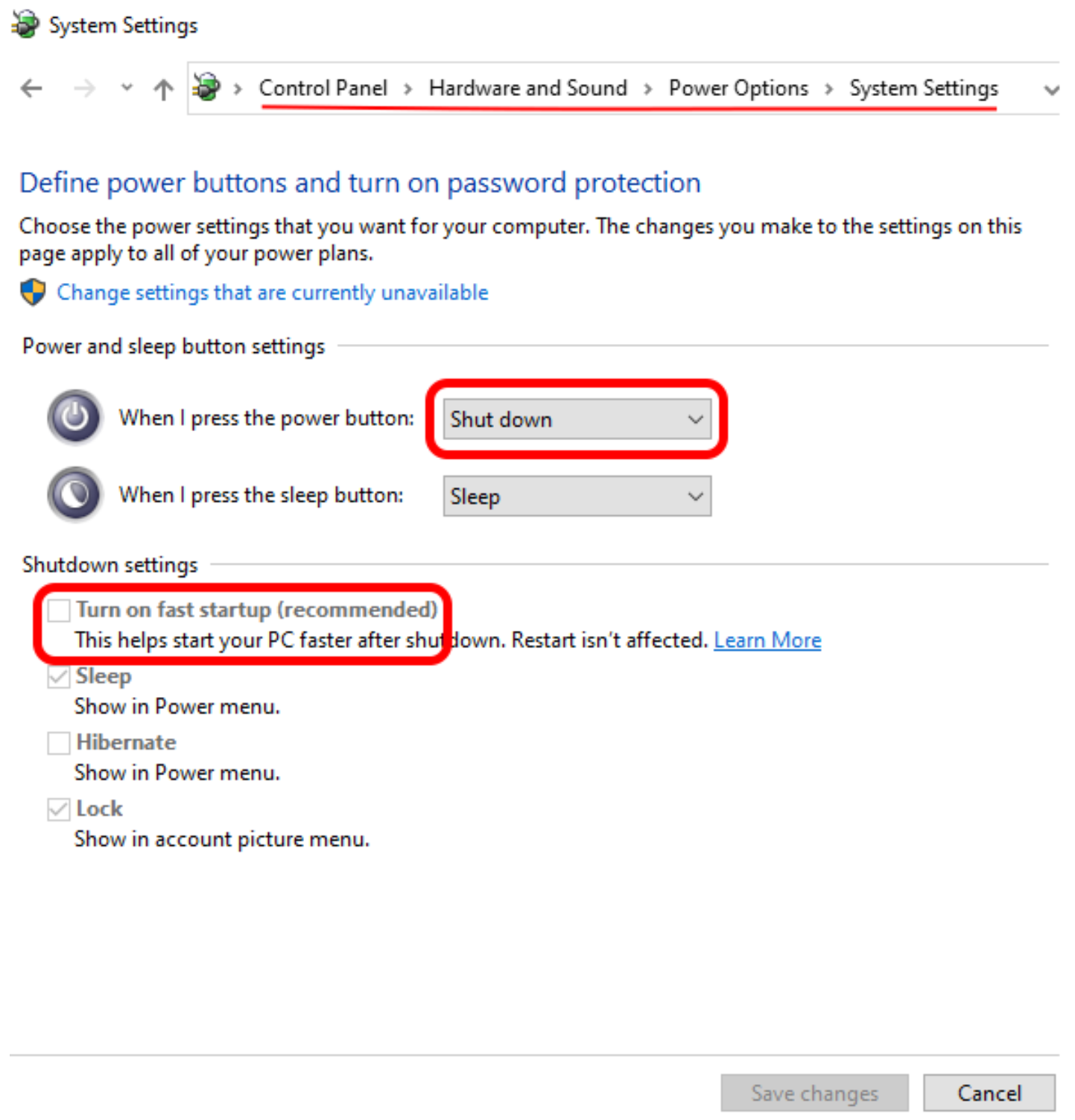


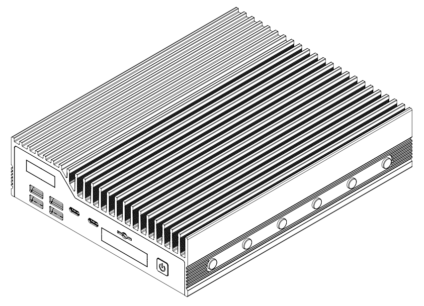
 | FCC 47 CFR Part 15 Subpart B (Class A) |
|
| FCC 47 CFR Part 15 Subpart B (Class A) |
|  |
|  | WEEE Directive (2012/19/EU) | |
|
| WEEE Directive (2012/19/EU) | |
|  | RoHS 3 (2015/863/EU) | |
|
| RoHS 3 (2015/863/EU) | |
|  | IEC 60601-1-2, 4th ed. - EMC Ready | |
|
| IEC 60601-1-2, 4th ed. - EMC Ready | |
|  | EN 60945, 4th ed. | |
|
| EN 60945, 4th ed. | |
|  | IEC/UL/EN 62368-1 | |
| **Radio Specifications when equipped with Intel AC 9260 Wi-Fi (device for indoor use)** | |
| --------------------------------------------------------------------------------------- | ------------------------------------------------------------------------------------------------------------------------------------------------------------------------------------- |
| **Frequency Bands** | 2.4 GHz and 5 GHz bands |
| **Operating Frequency** |
| IEC/UL/EN 62368-1 | |
| **Radio Specifications when equipped with Intel AC 9260 Wi-Fi (device for indoor use)** | |
| --------------------------------------------------------------------------------------- | ------------------------------------------------------------------------------------------------------------------------------------------------------------------------------------- |
| **Frequency Bands** | 2.4 GHz and 5 GHz bands |
| **Operating Frequency** | 


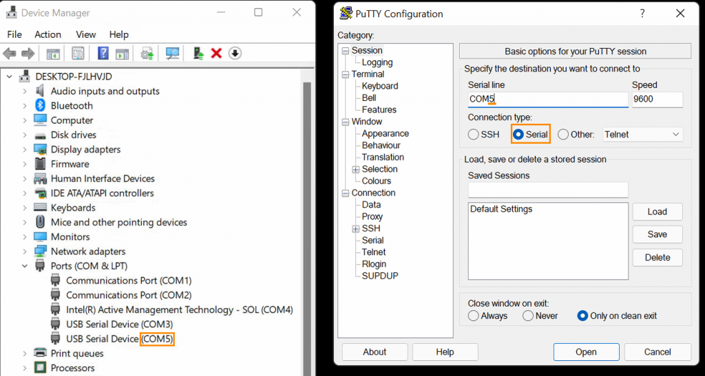


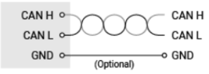


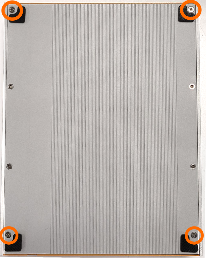
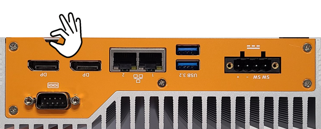
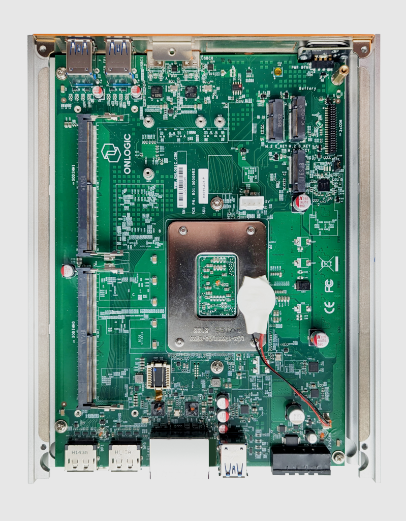


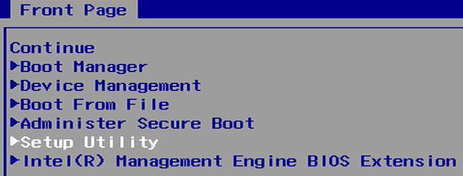
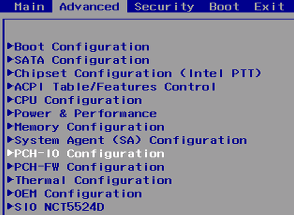
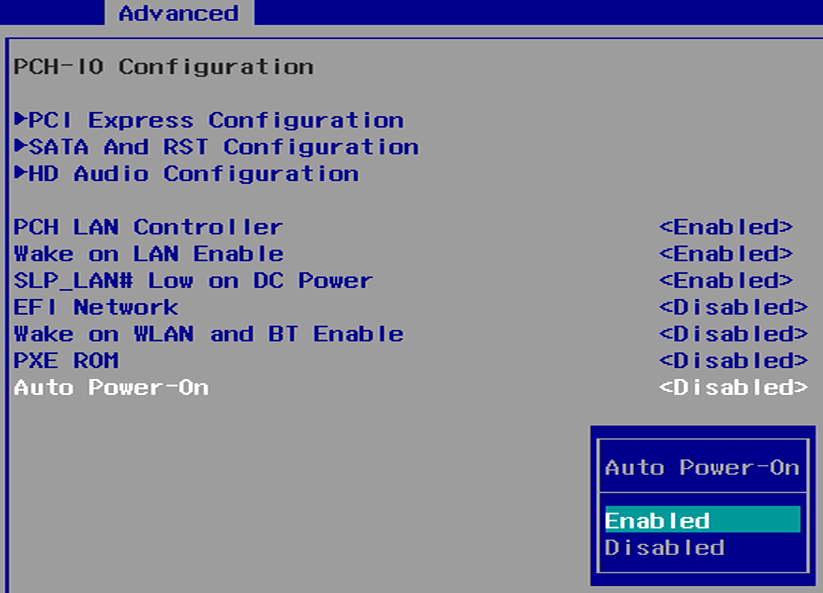
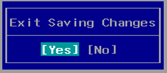


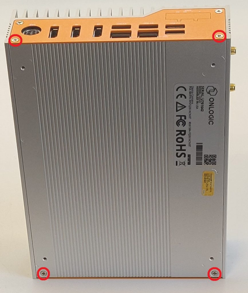
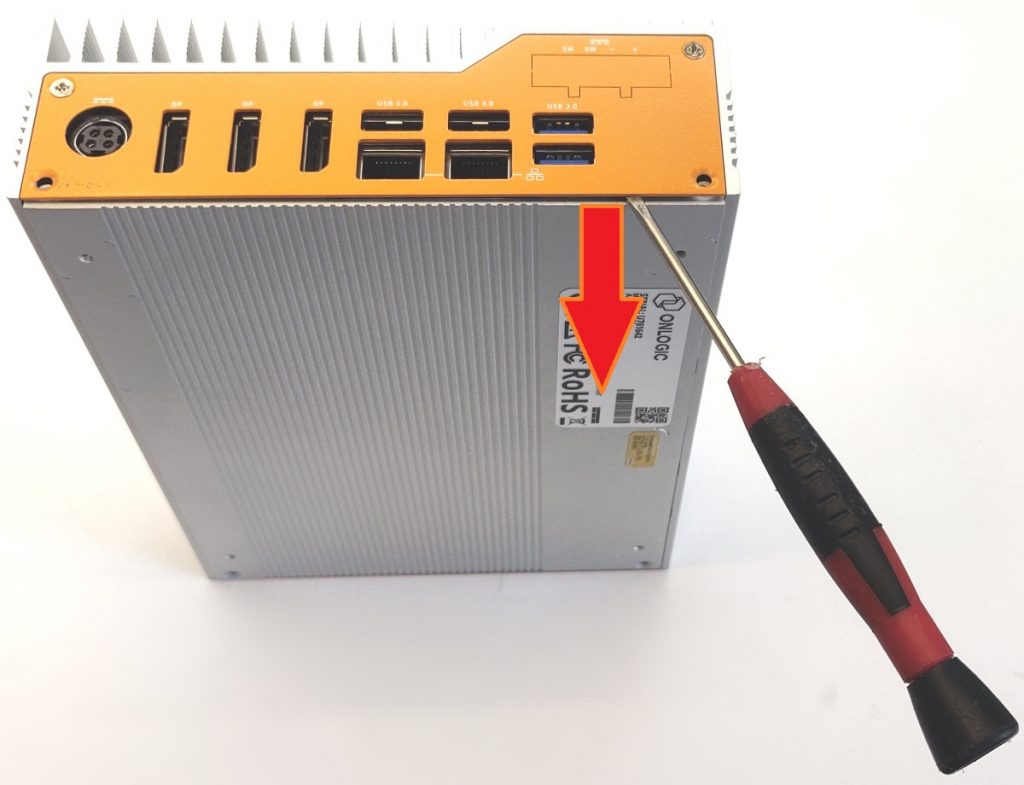
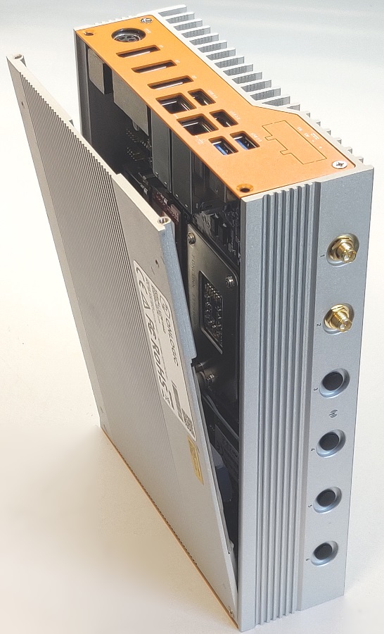
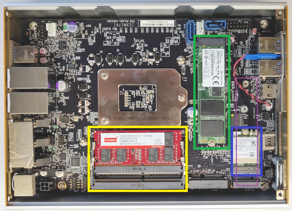
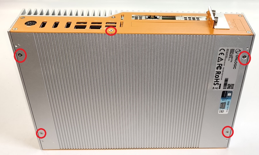
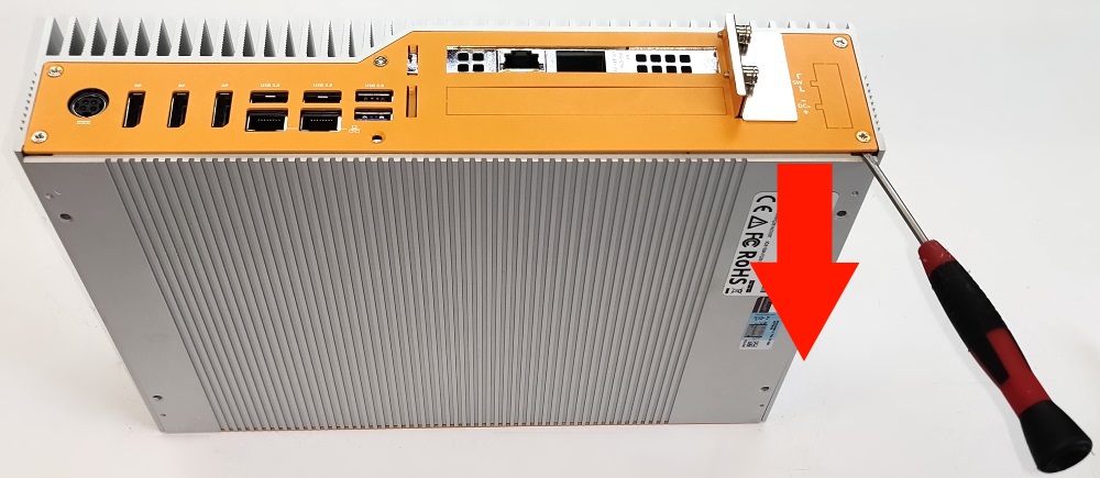
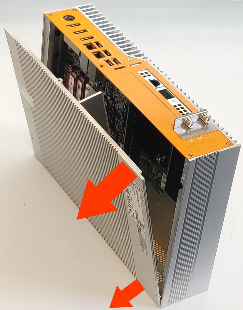
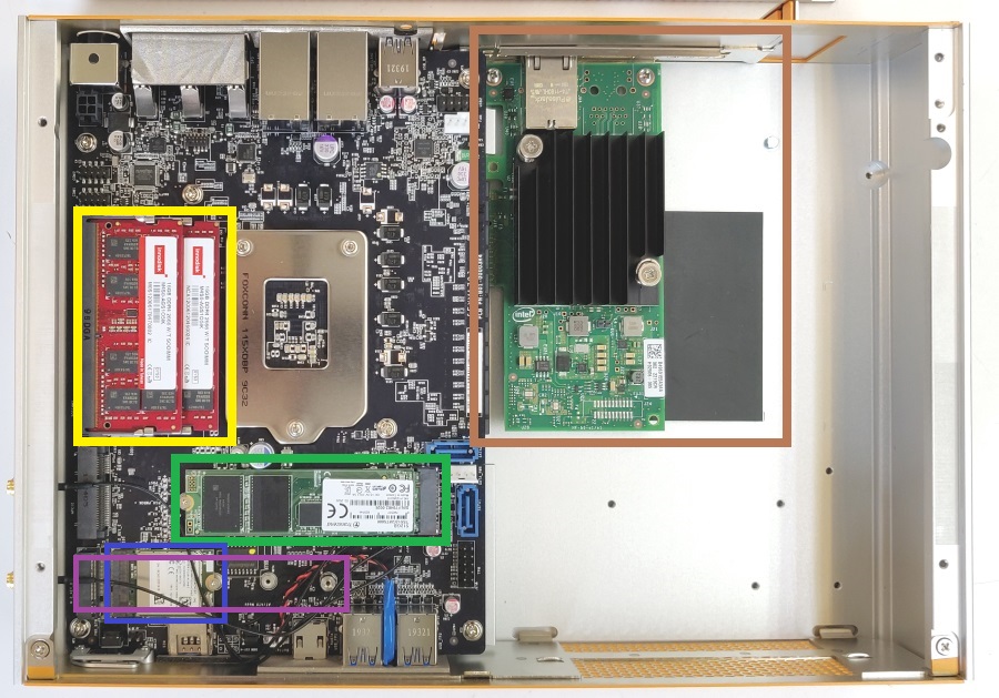
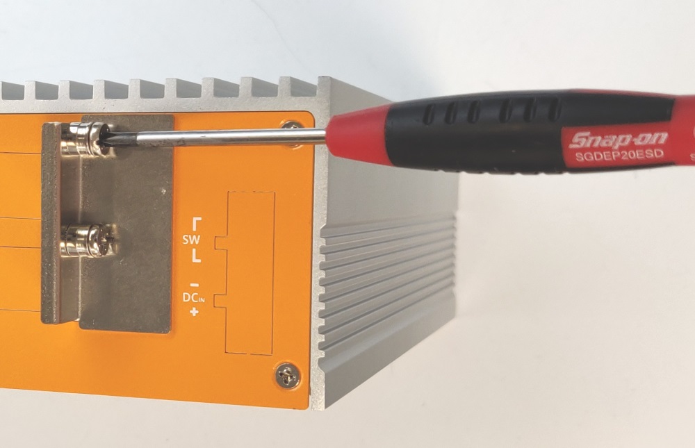
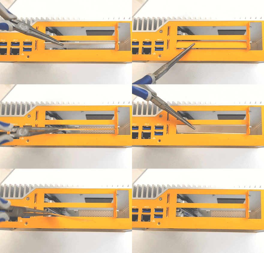
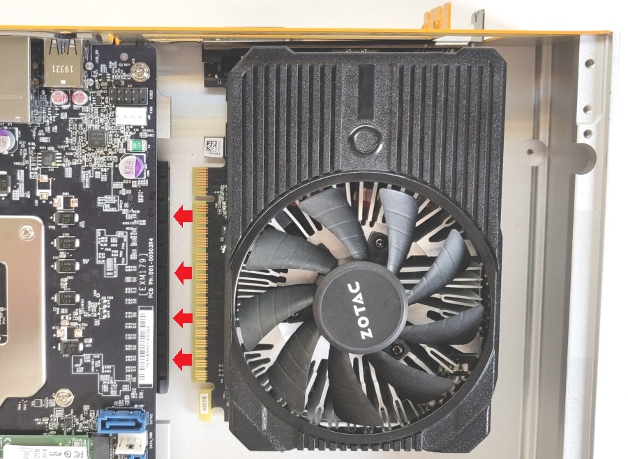
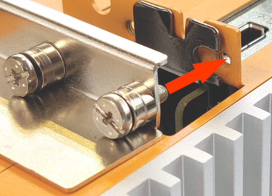
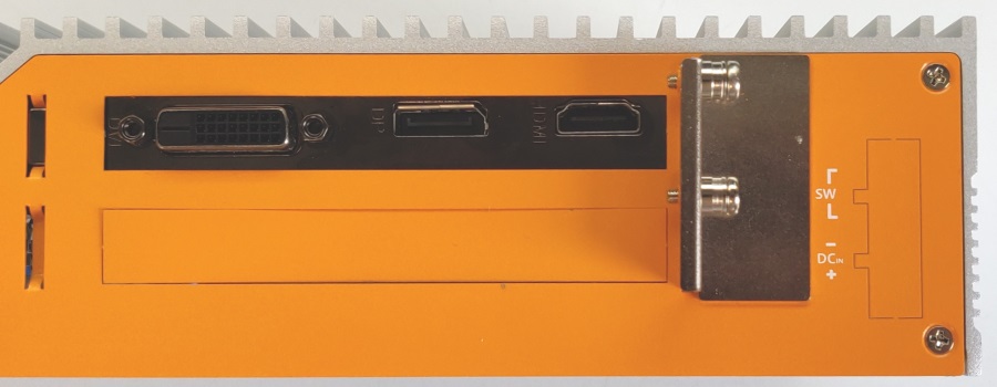
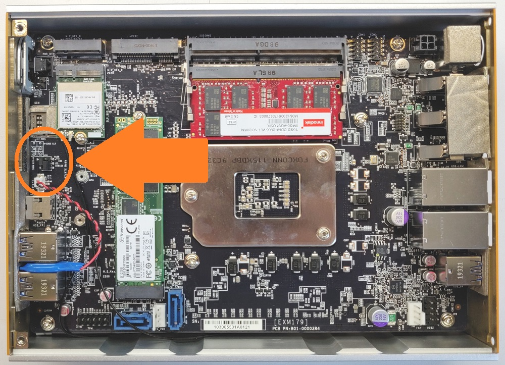
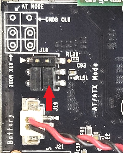
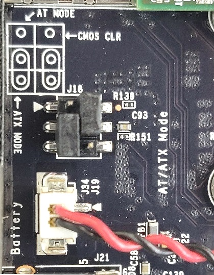
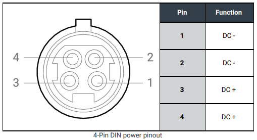
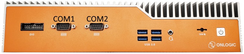
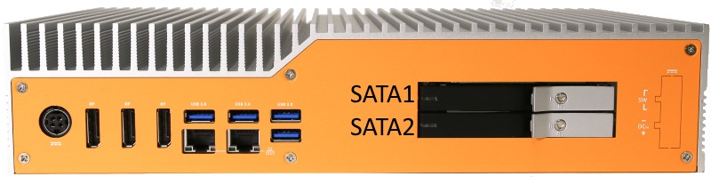
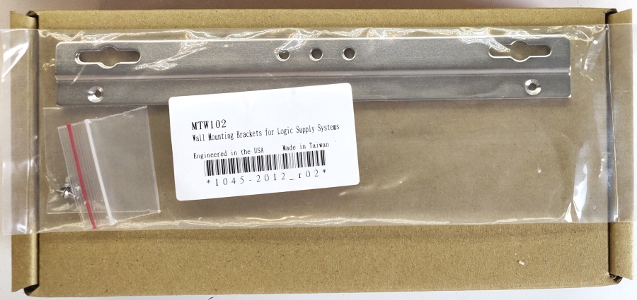
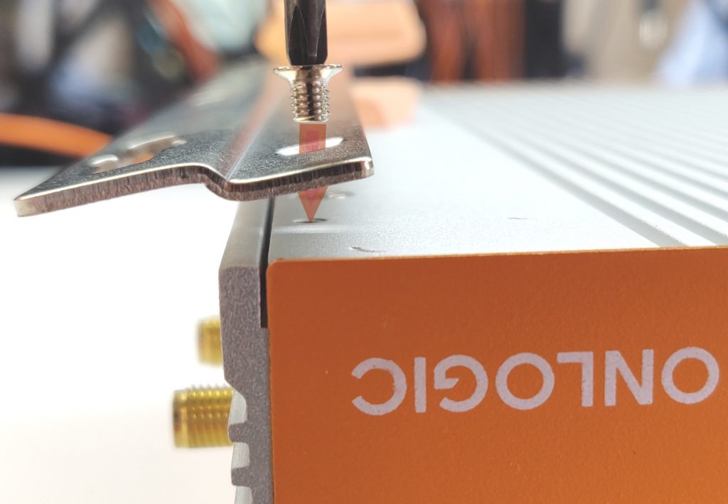
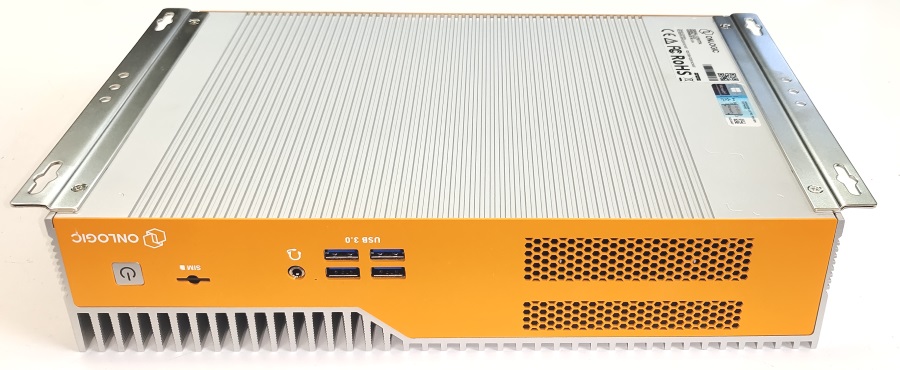
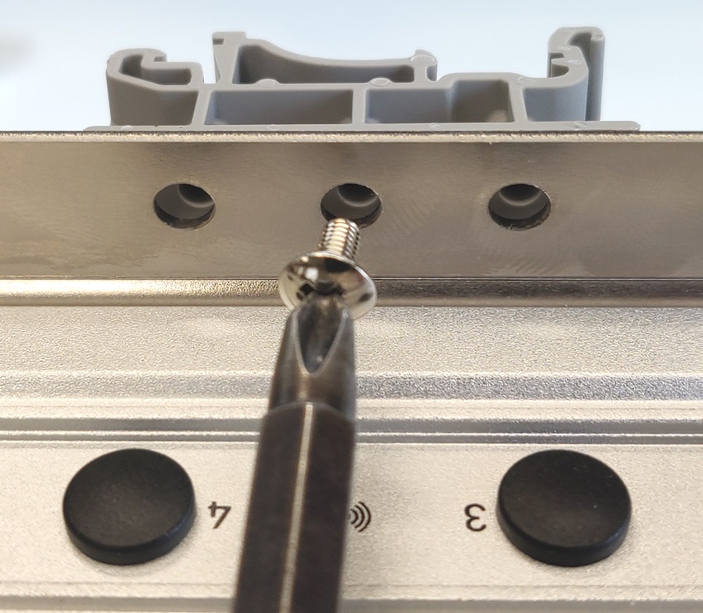
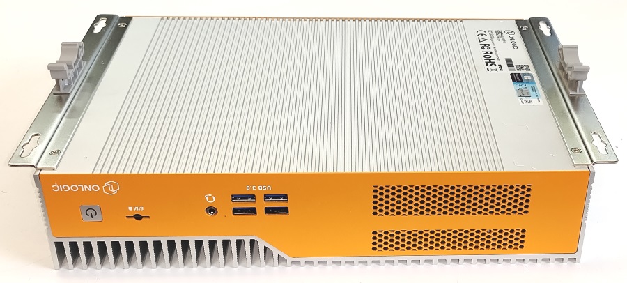



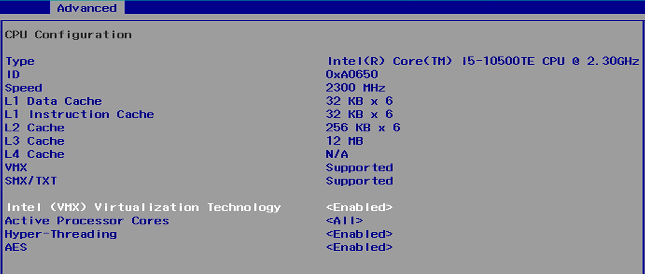

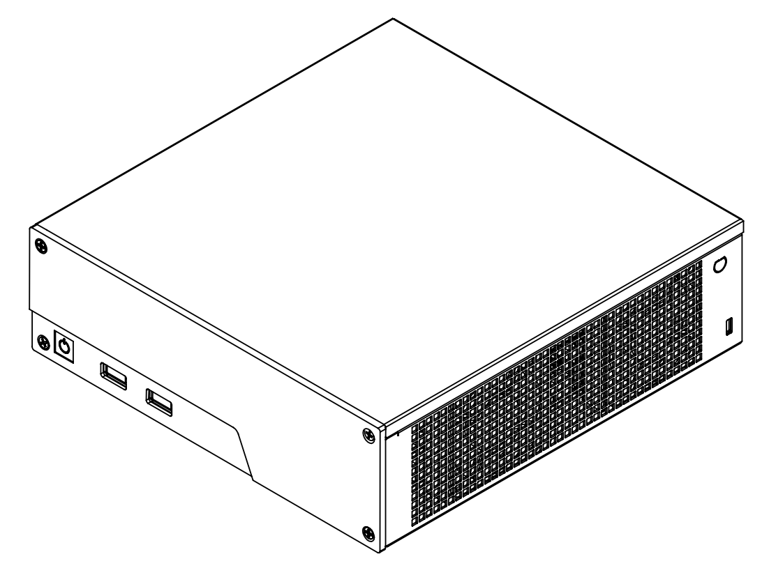


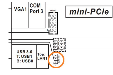

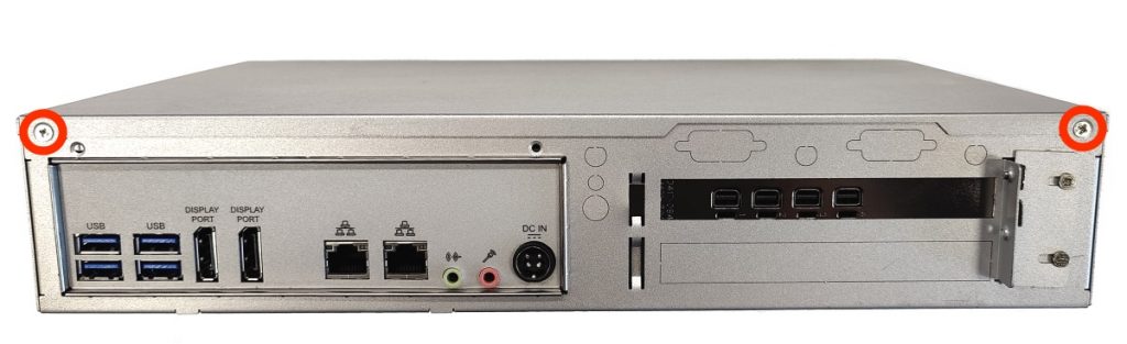
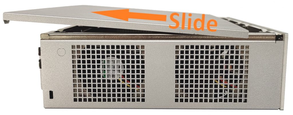
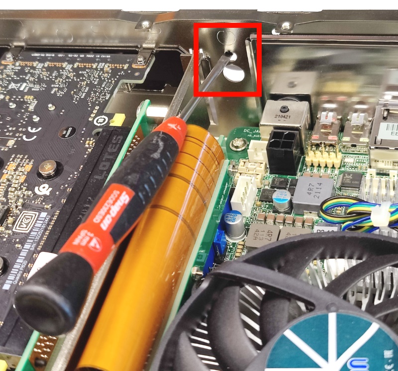
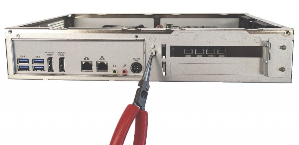
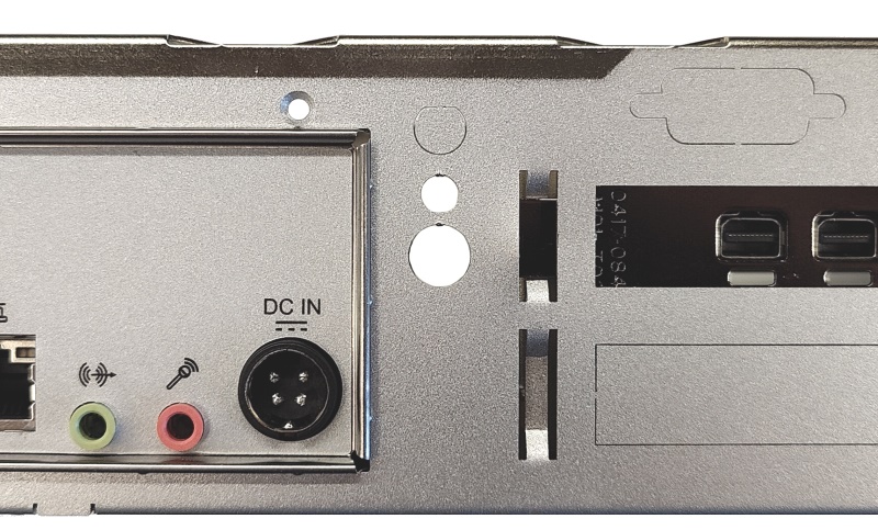
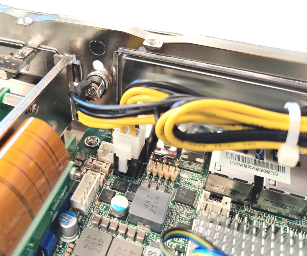
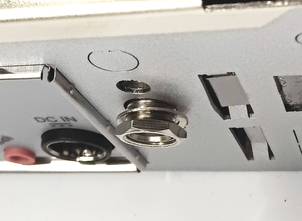
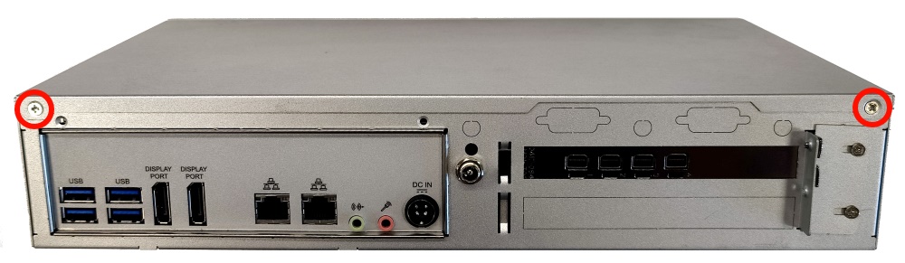
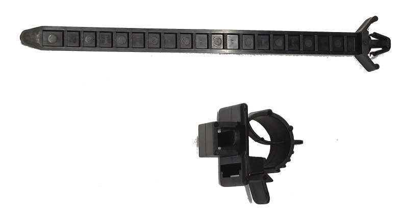
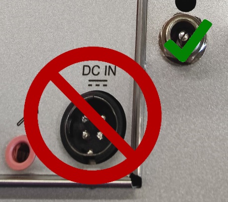
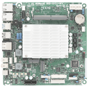
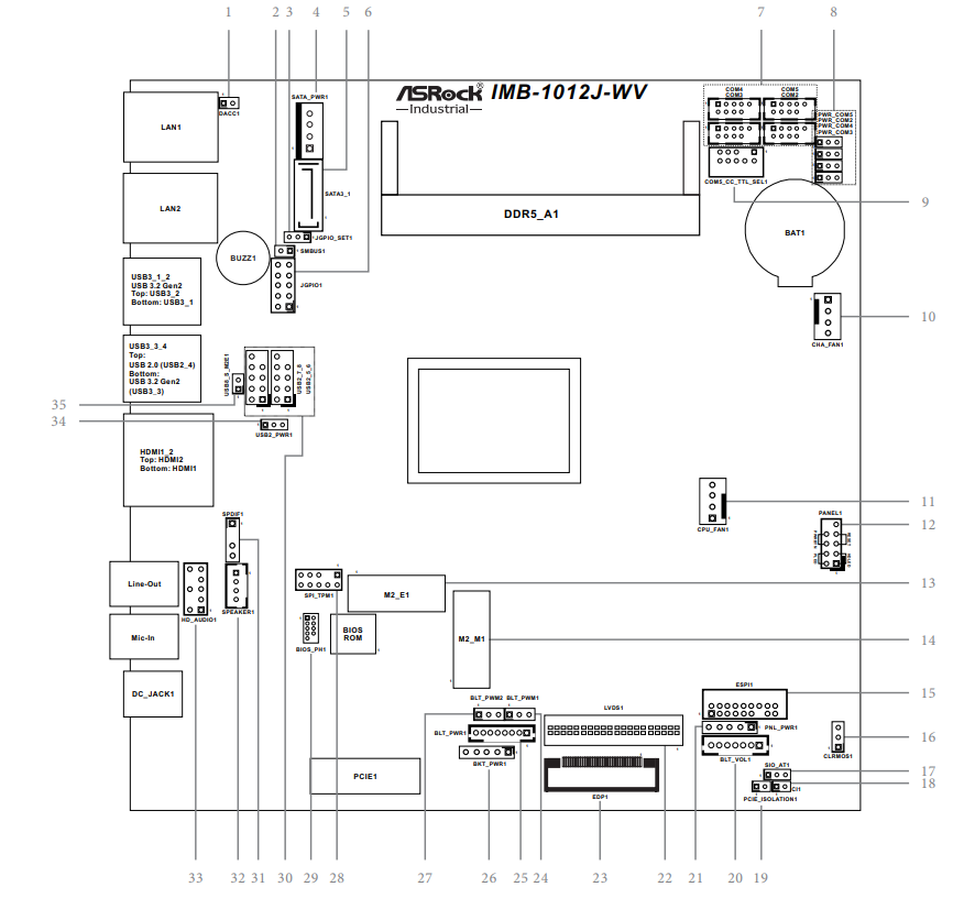
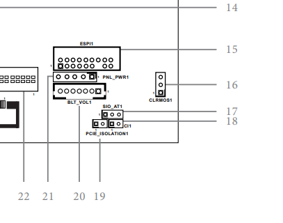
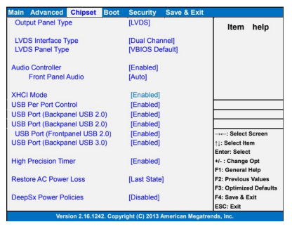
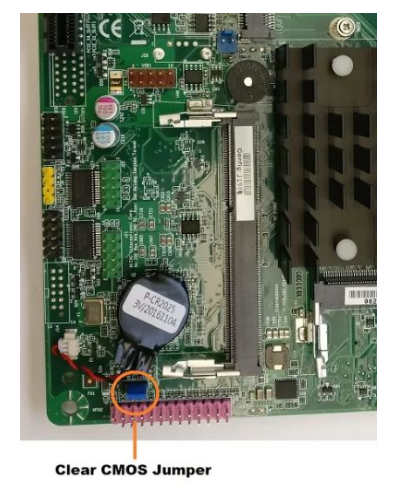


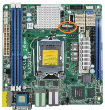
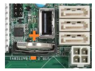

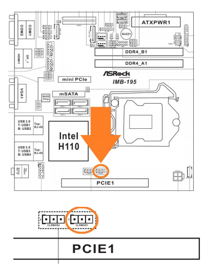
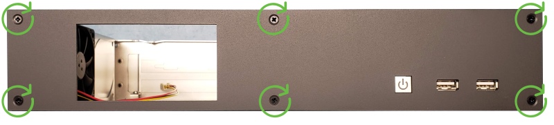
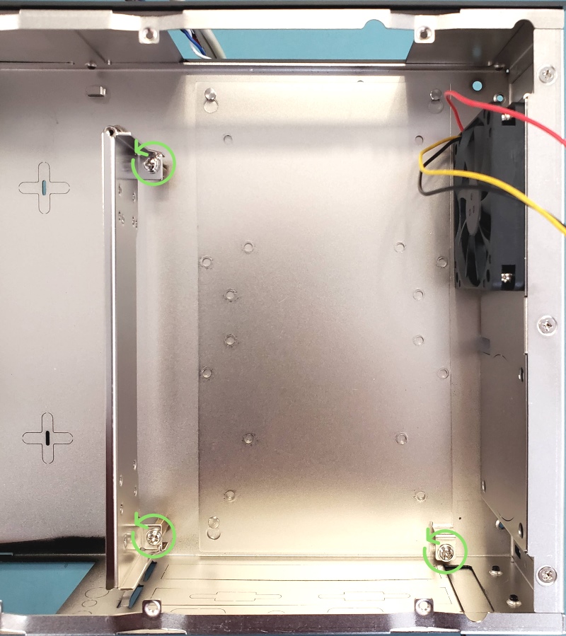
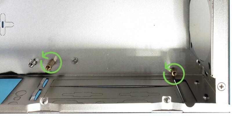
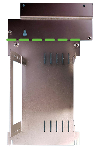
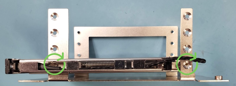
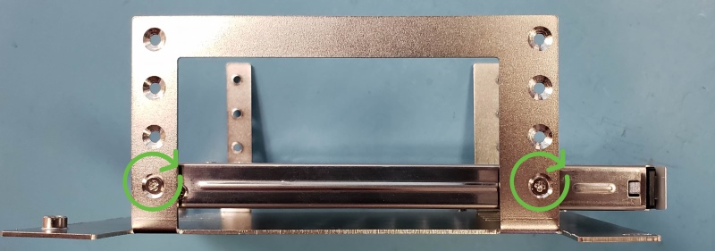
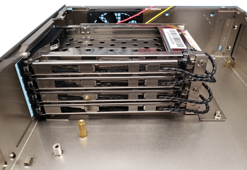
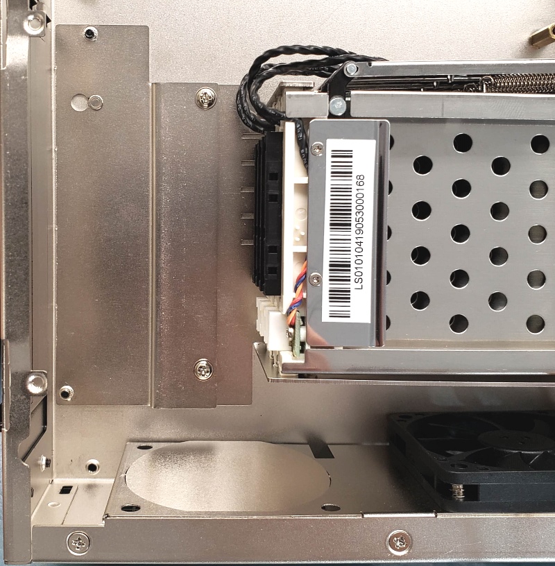
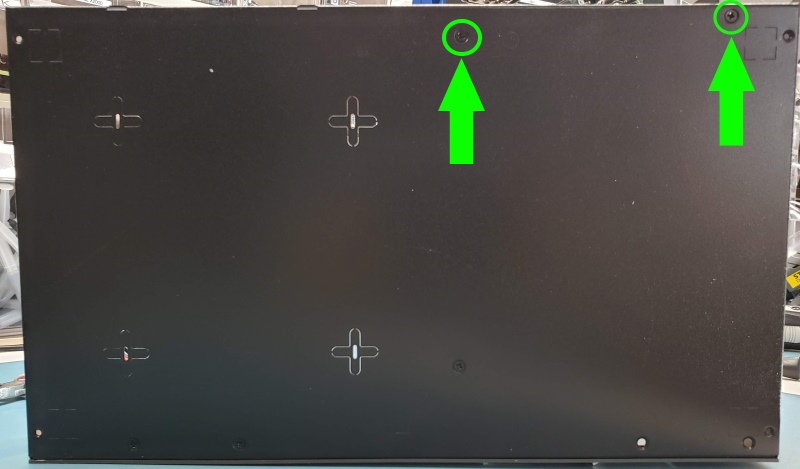
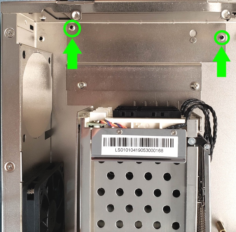
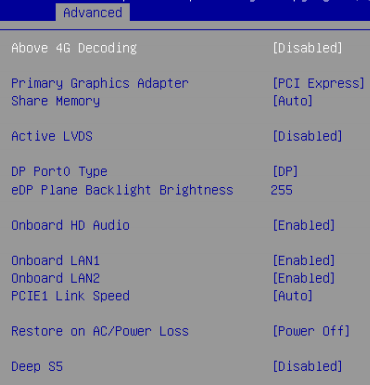
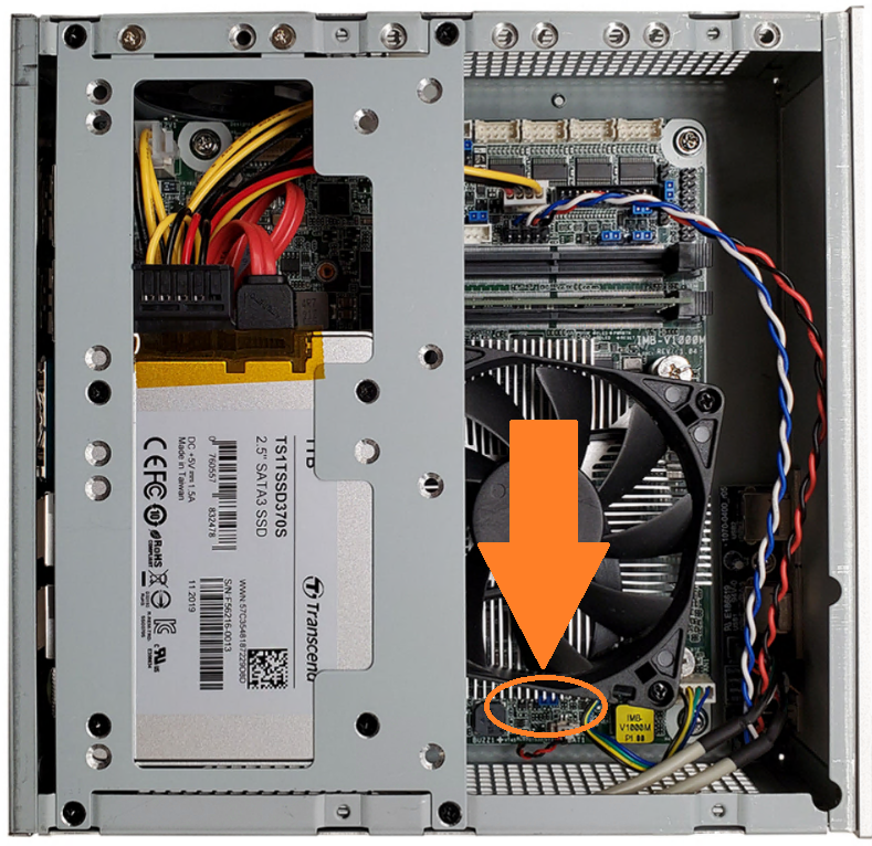
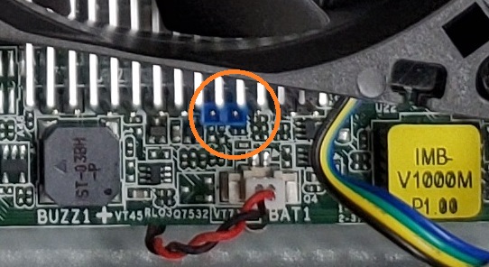
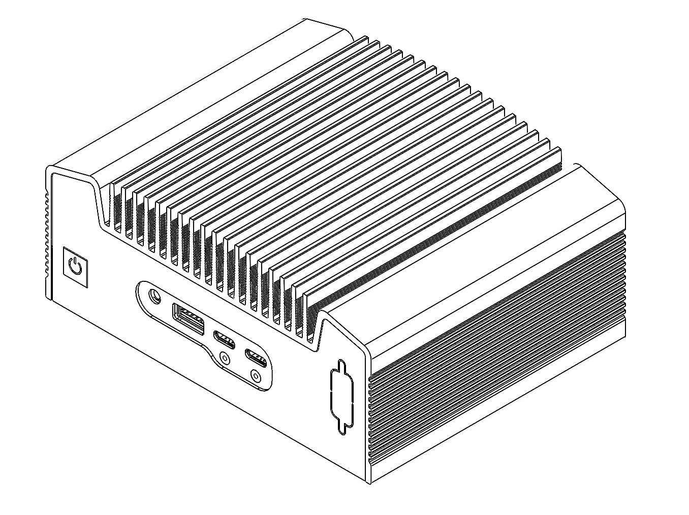


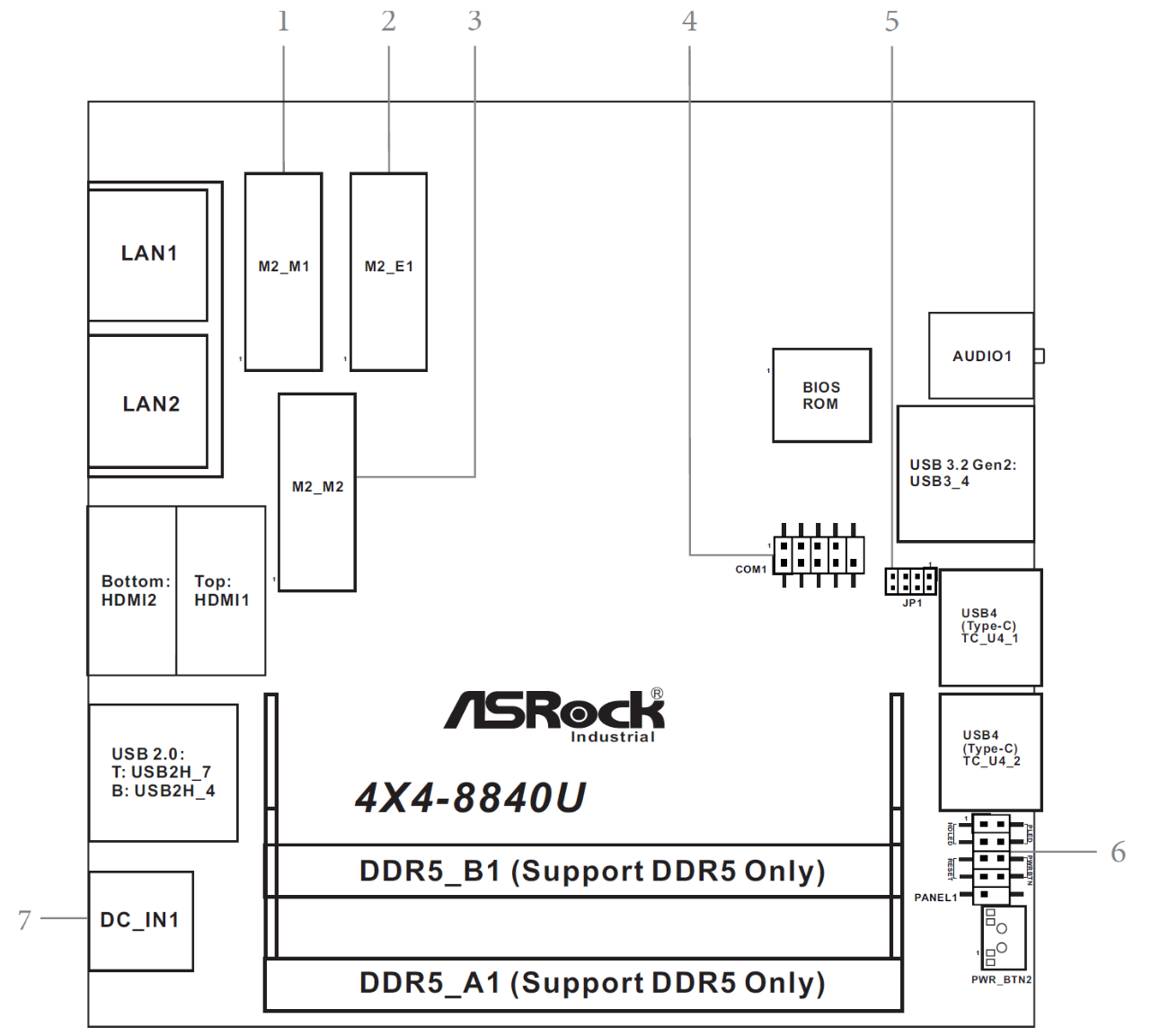


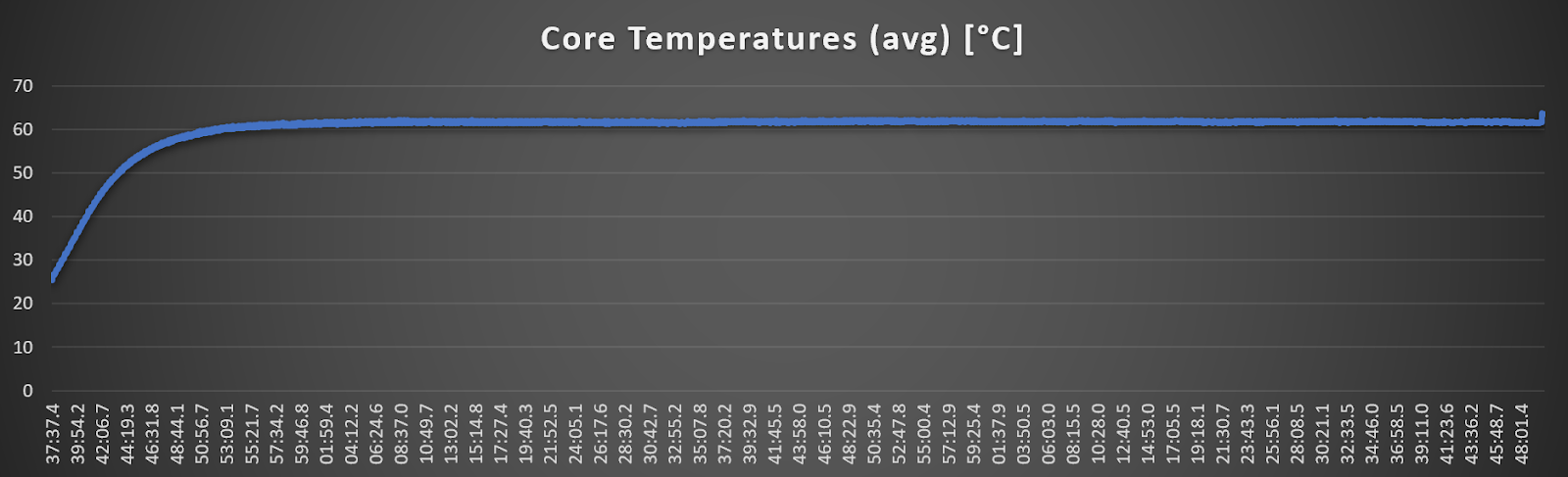
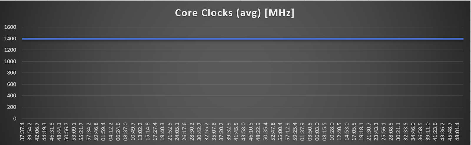
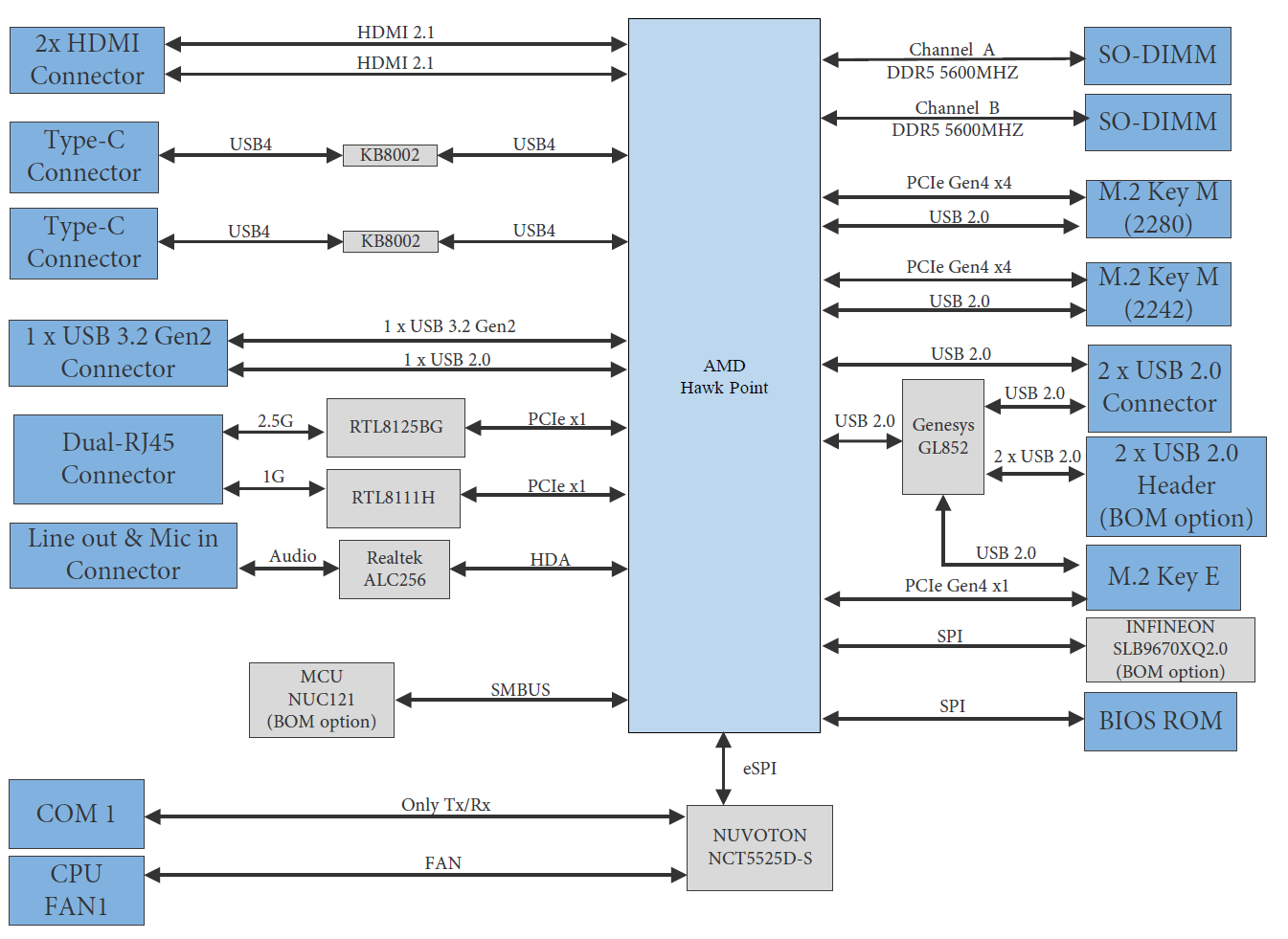
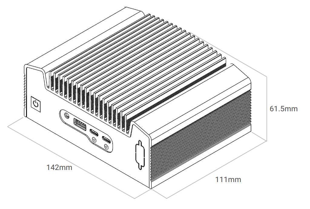
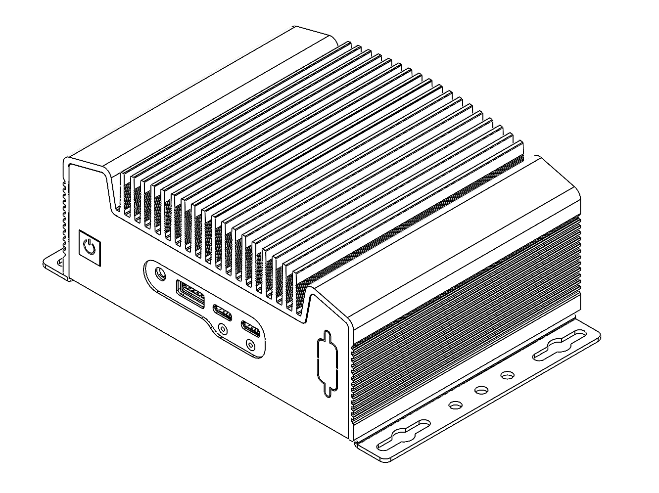
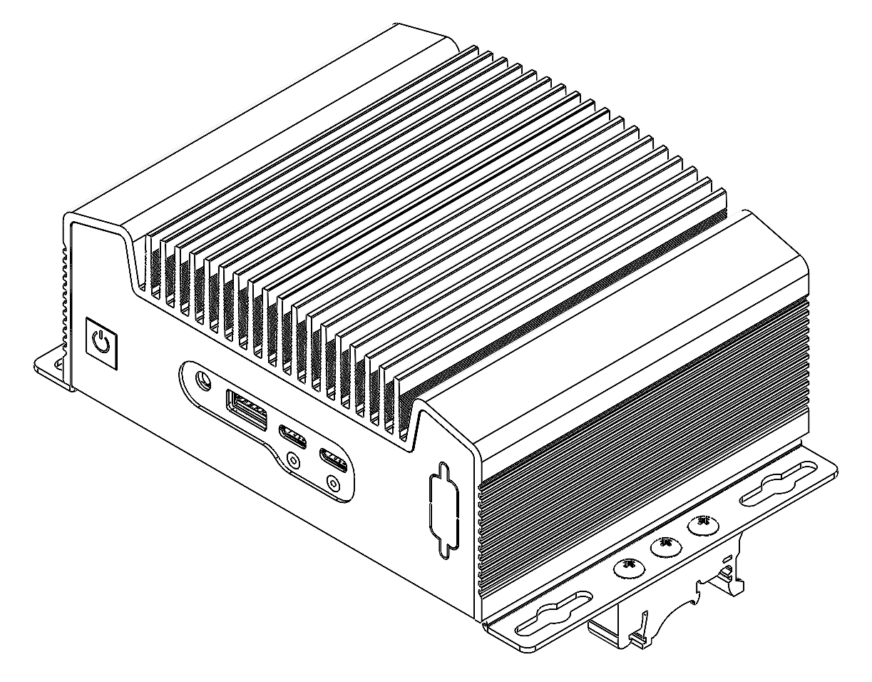
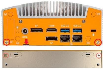


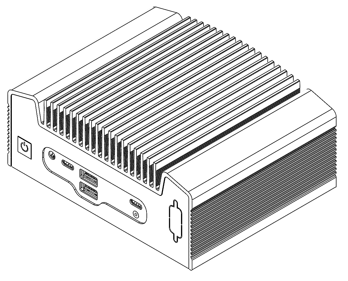


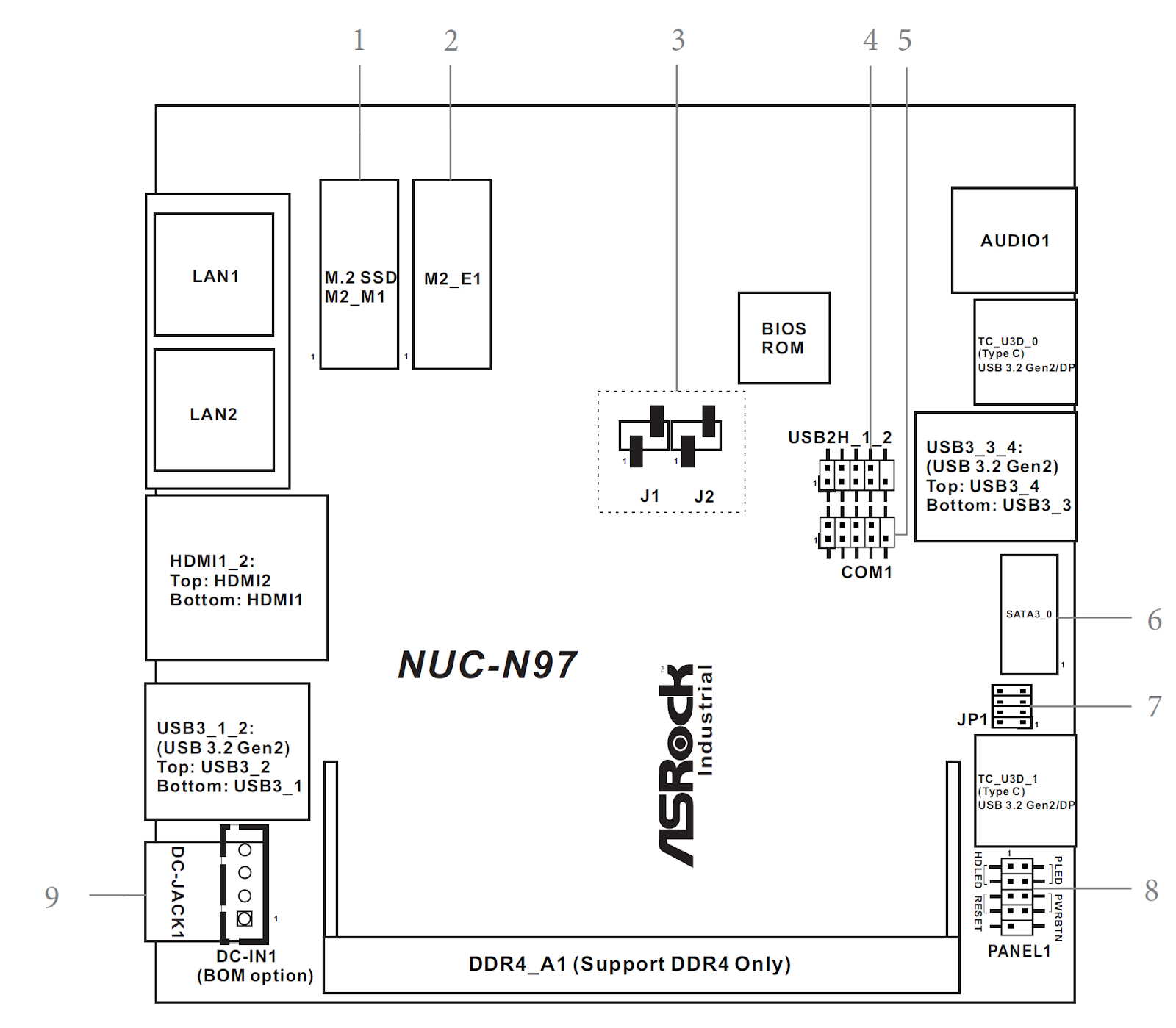


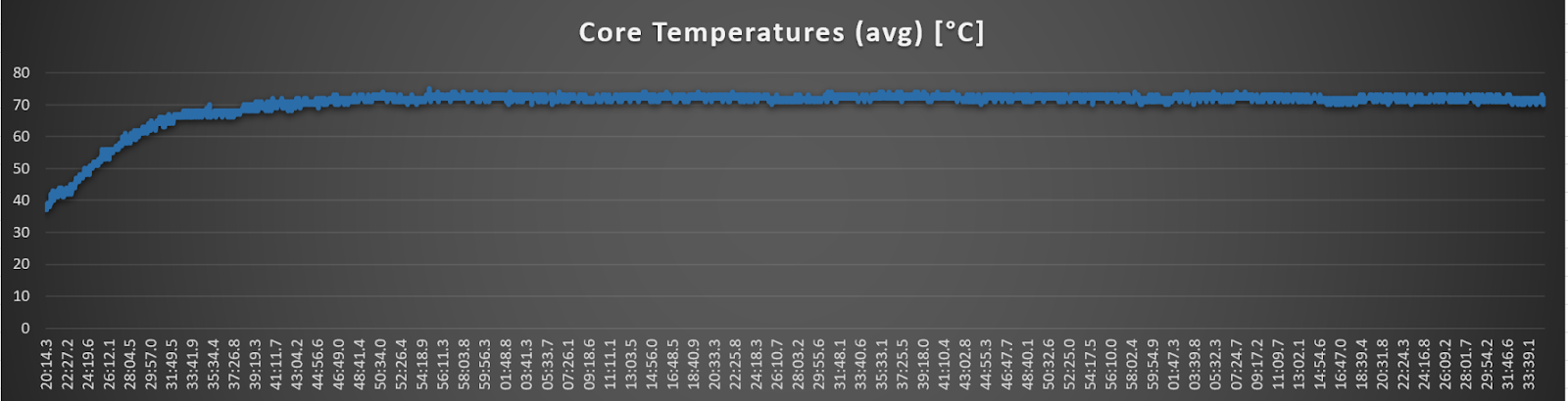
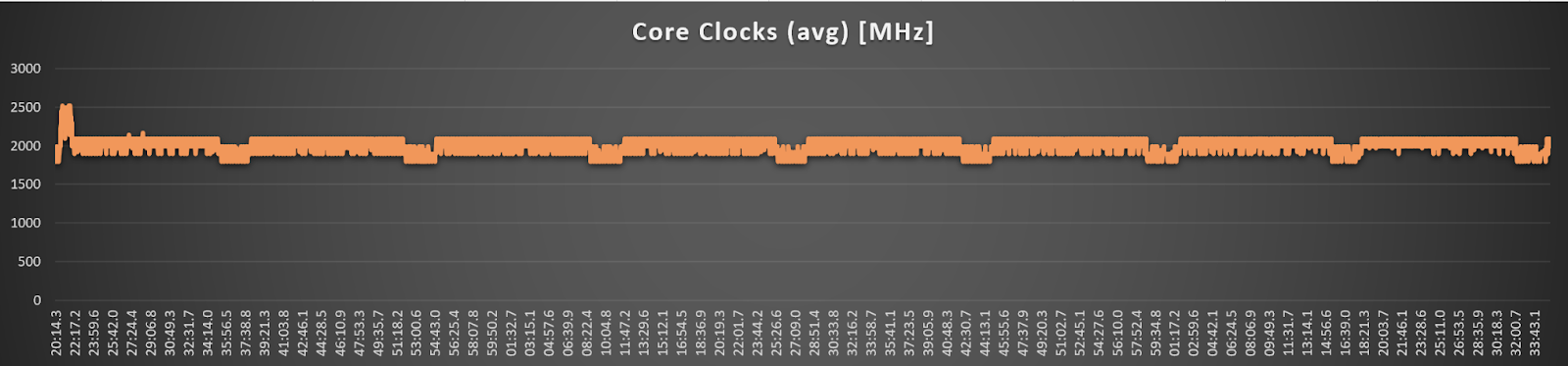
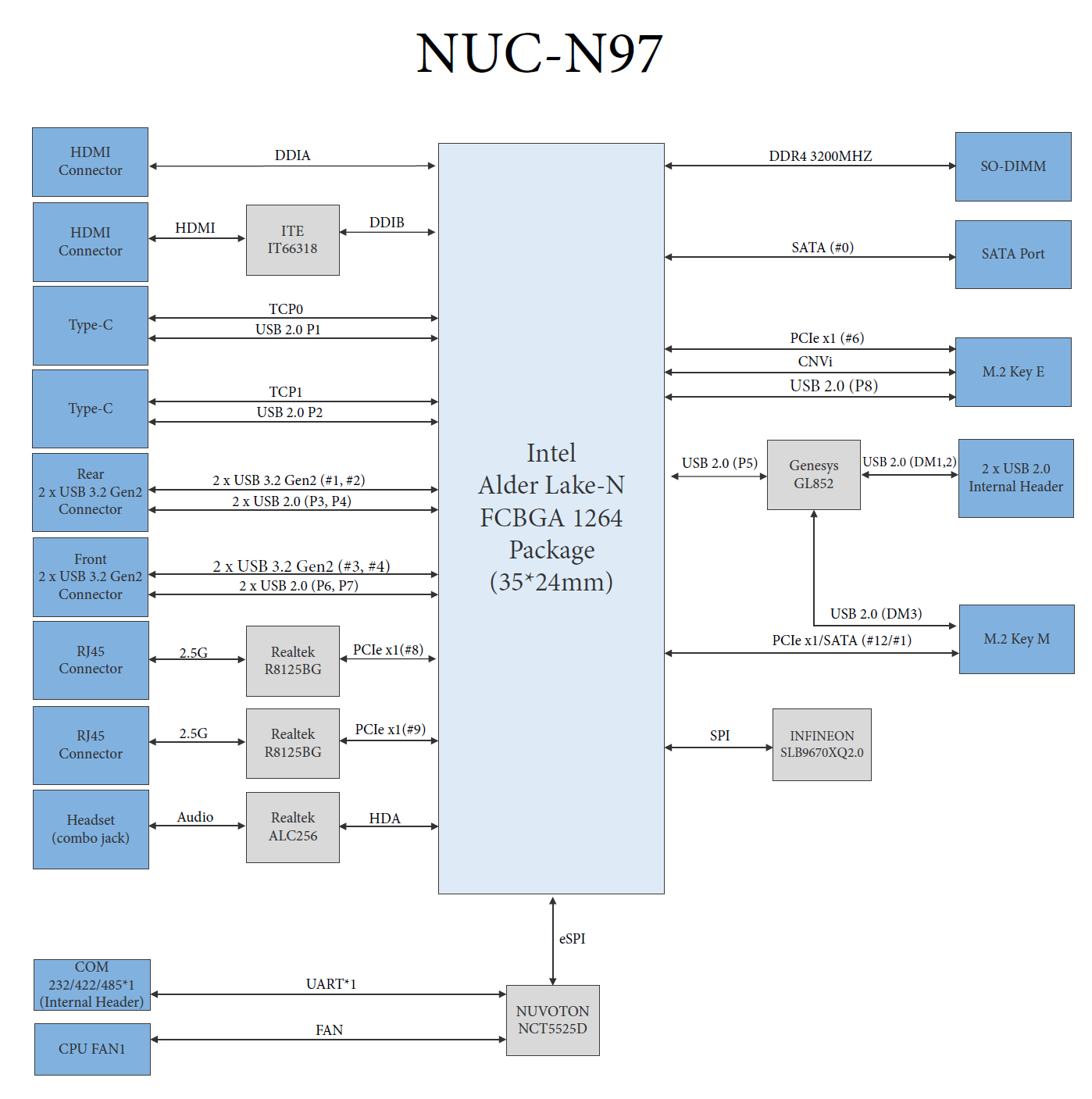
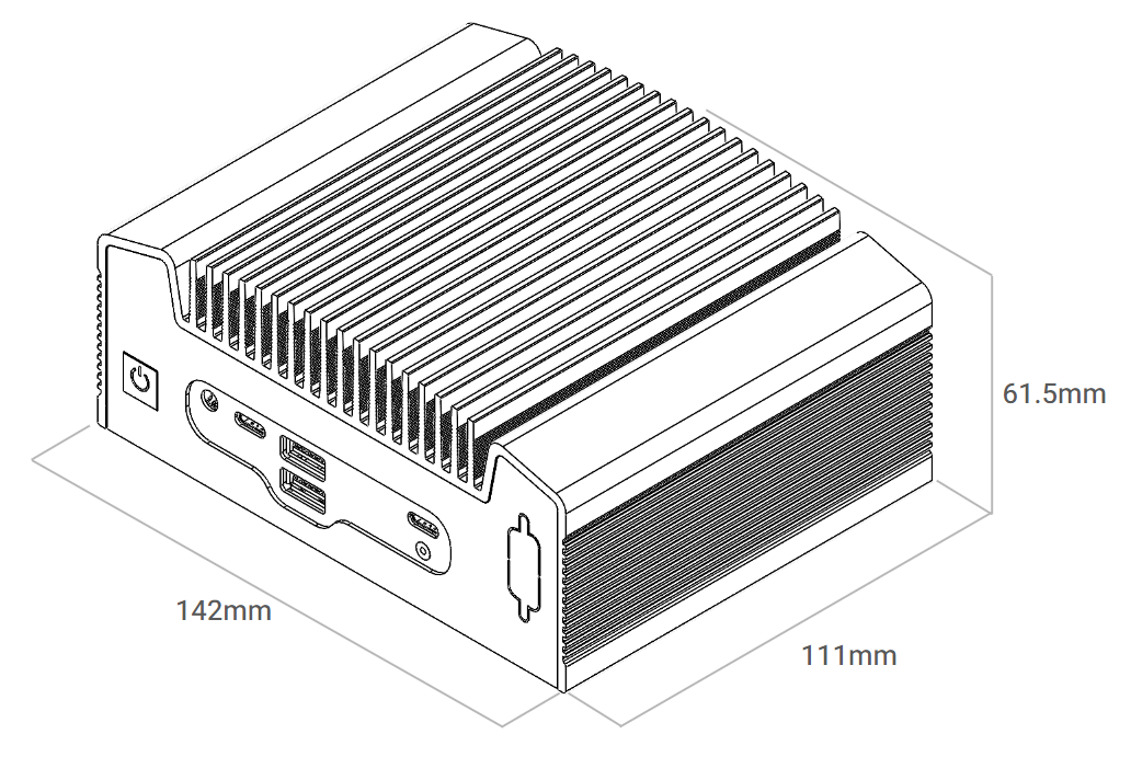
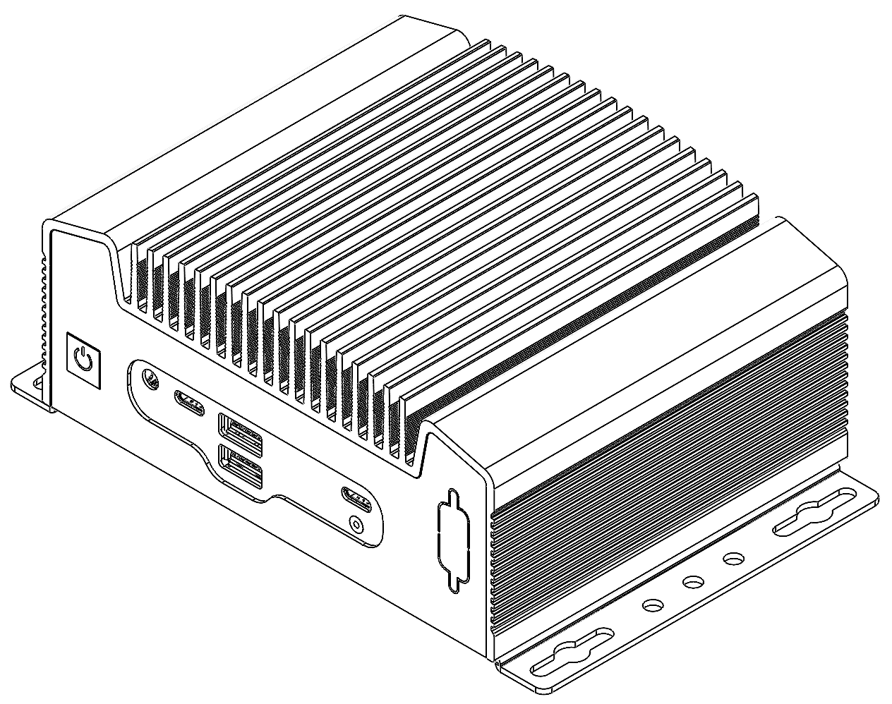
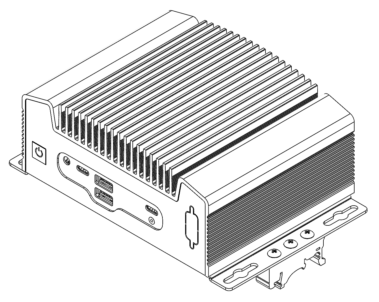


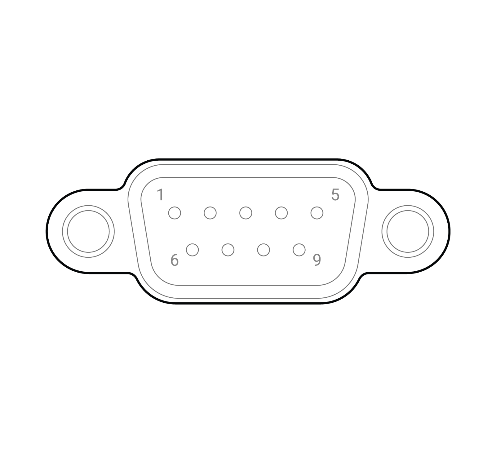


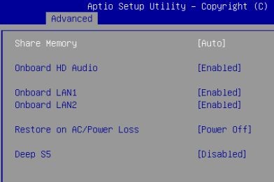
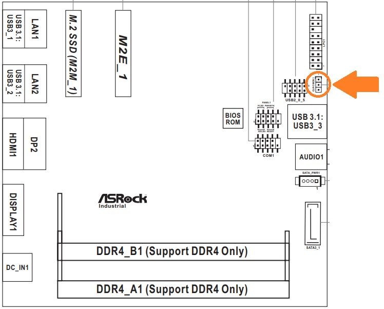
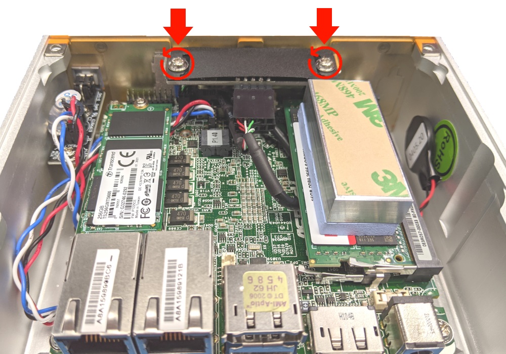
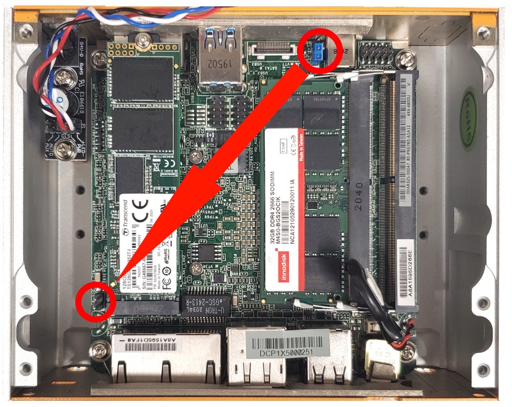
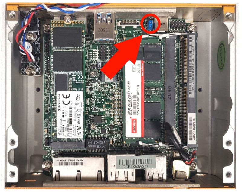
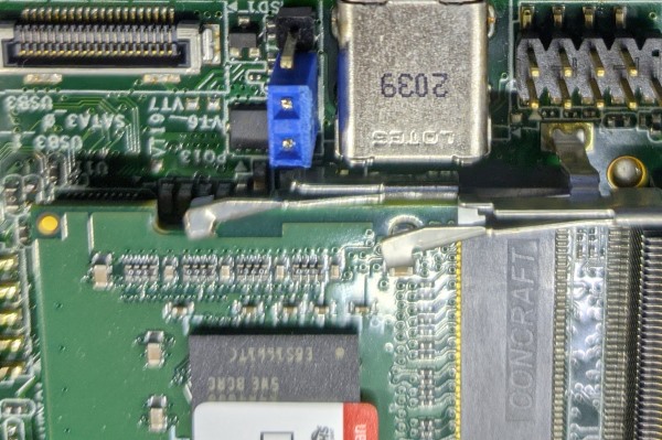
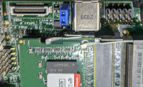
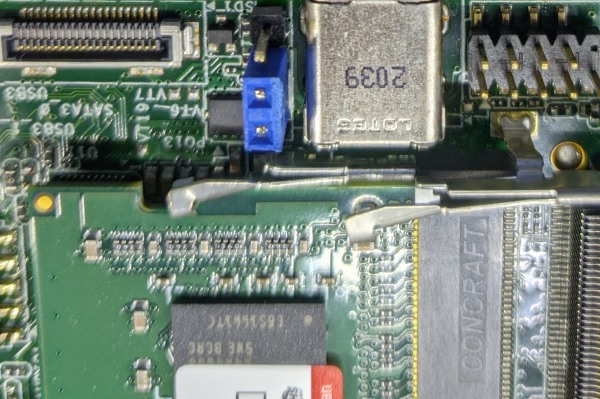
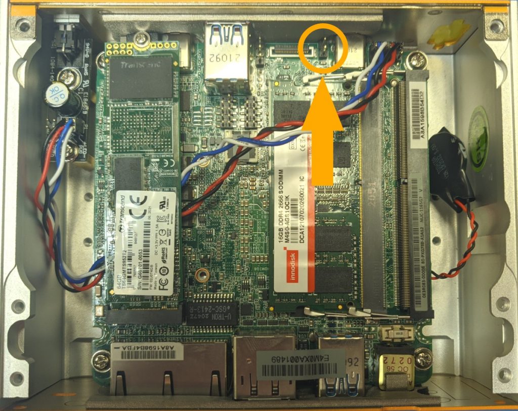
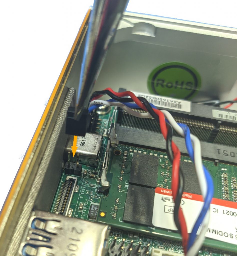
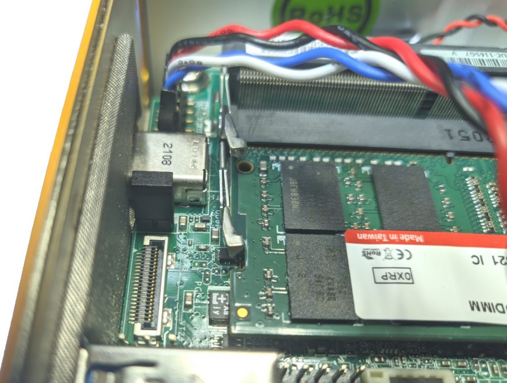
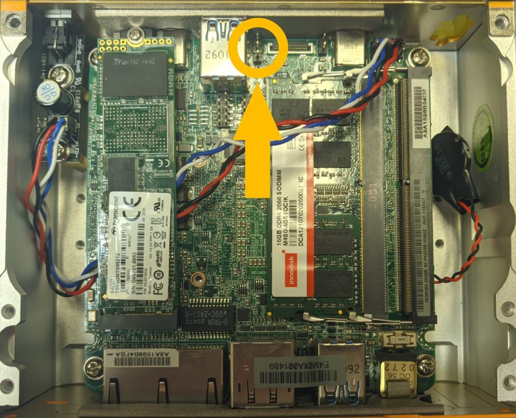
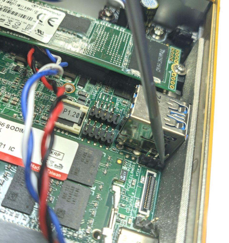
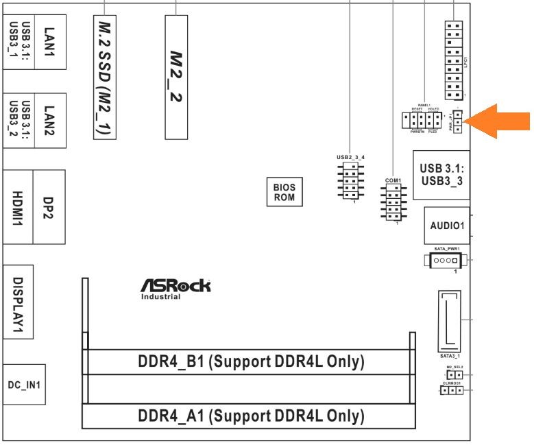
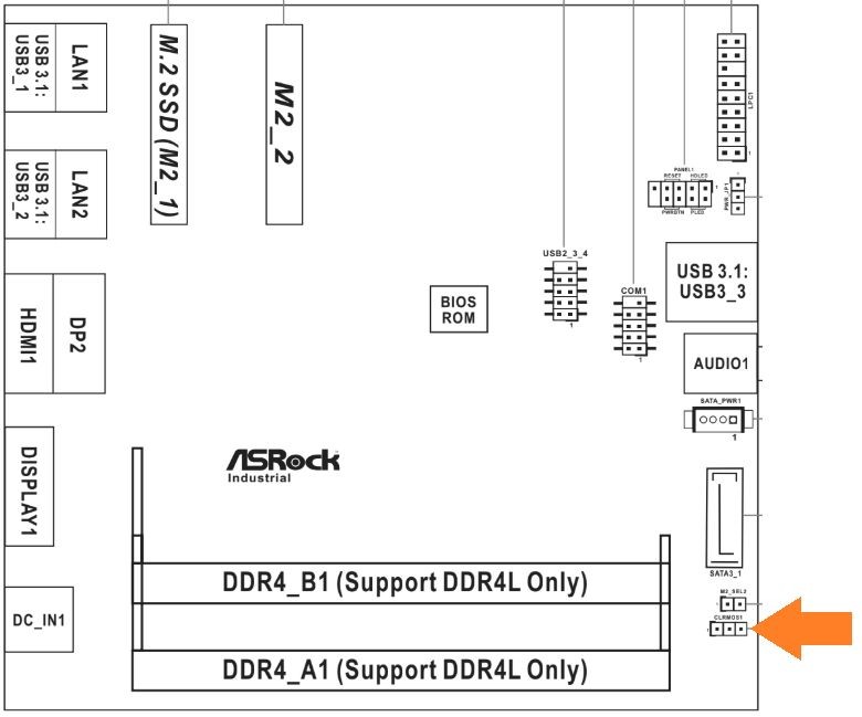
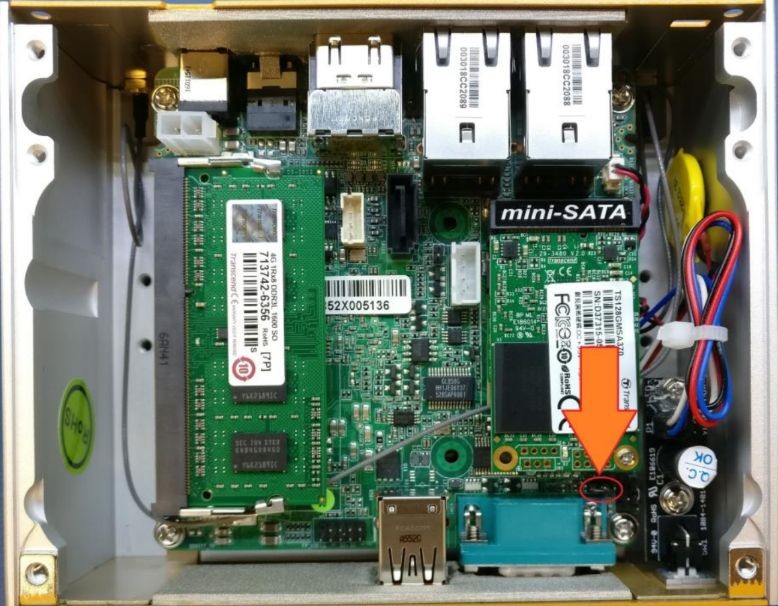

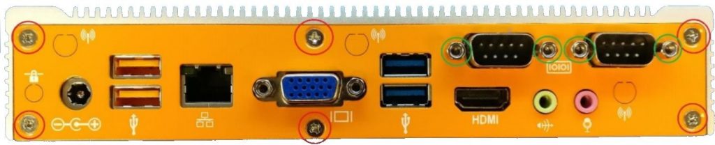

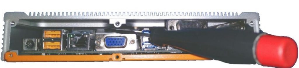
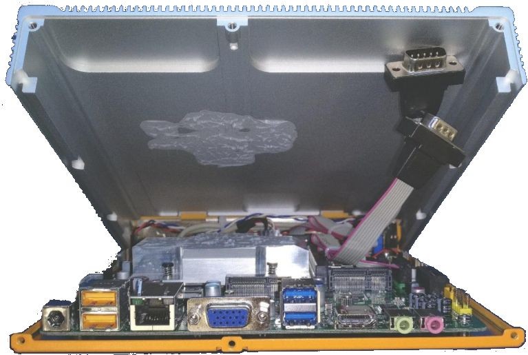
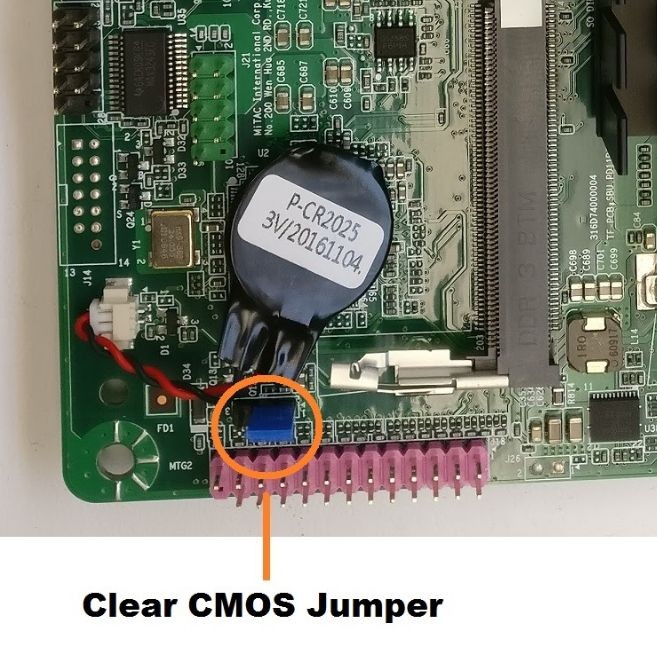
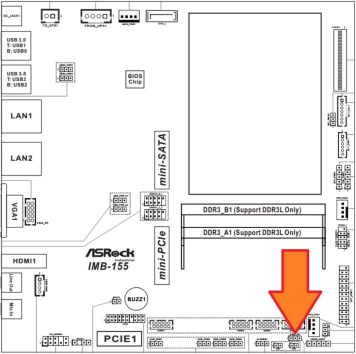
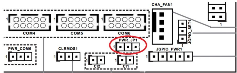
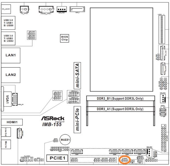
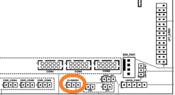
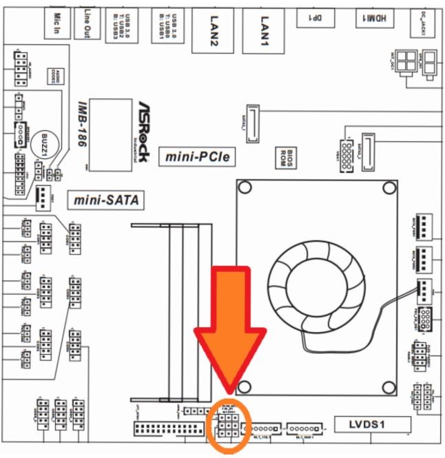
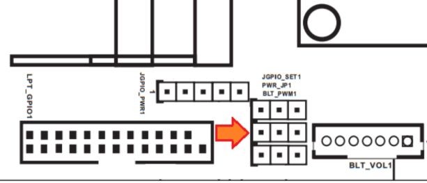
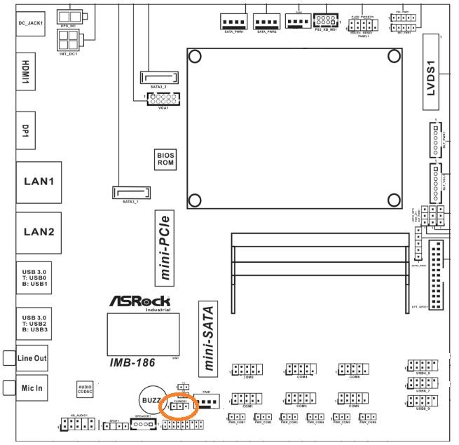
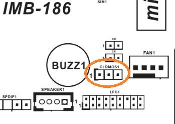
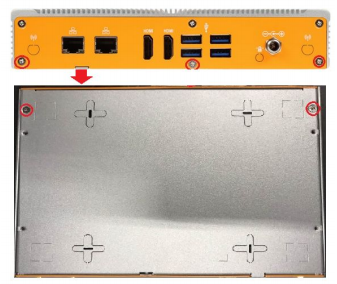
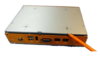
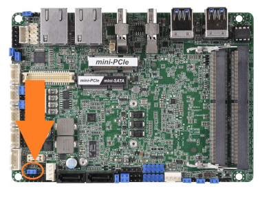
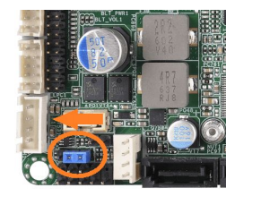
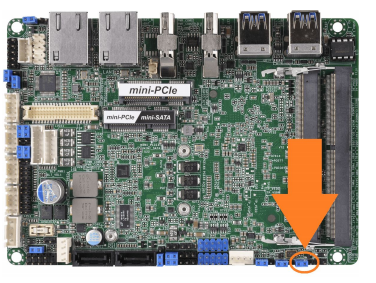
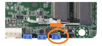
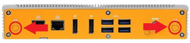
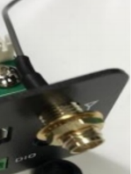
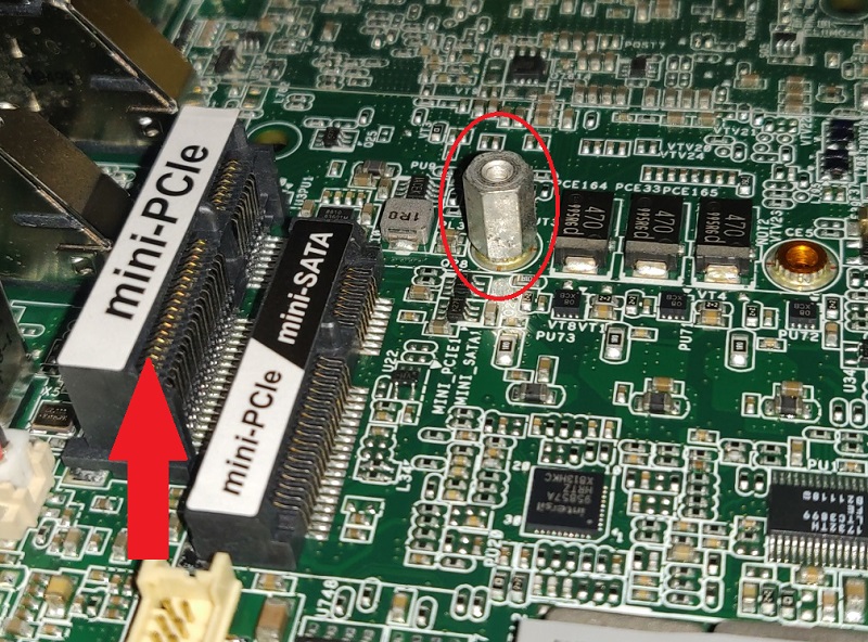
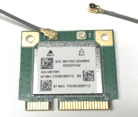

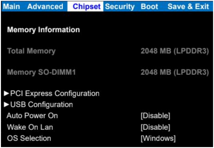
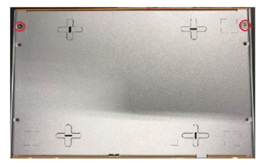
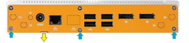
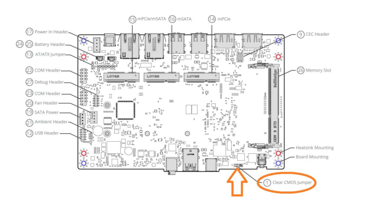
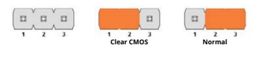
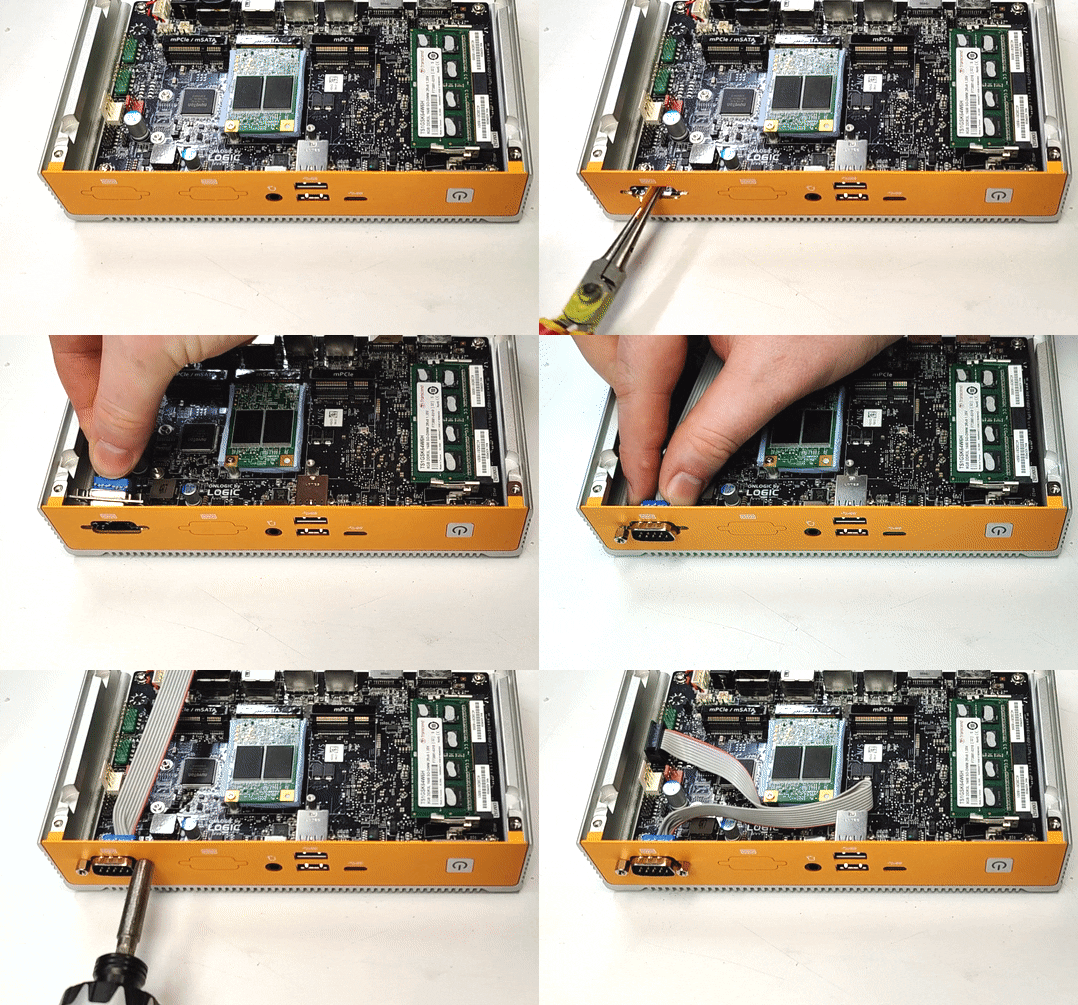
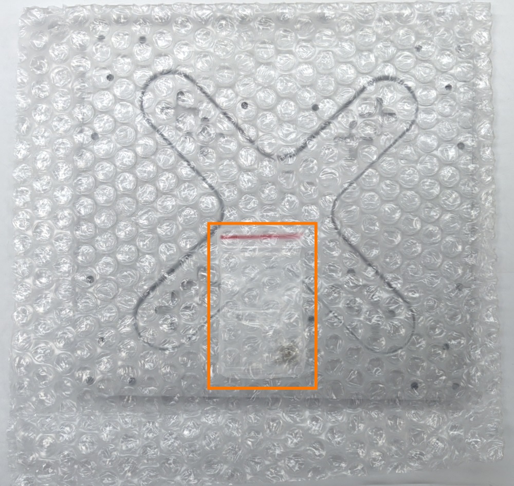
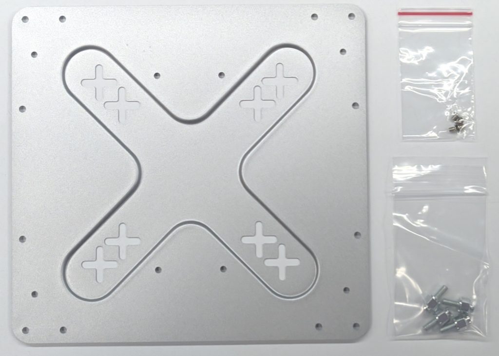
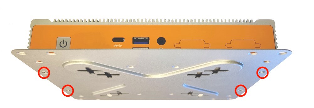
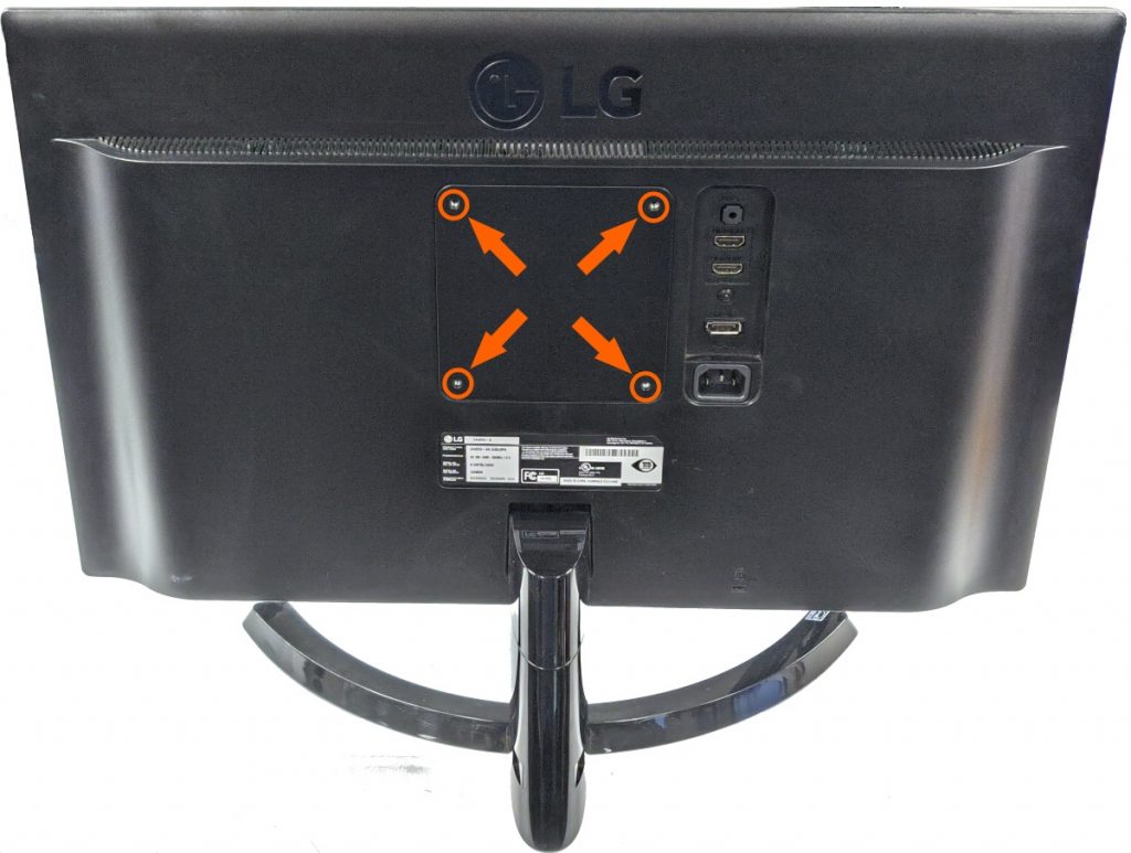
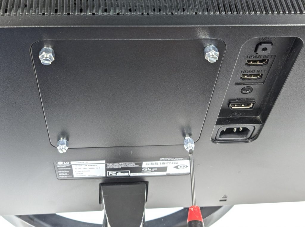
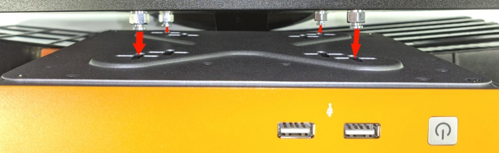
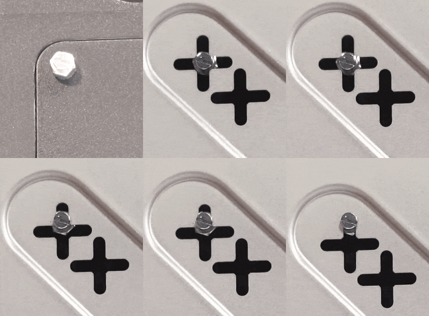
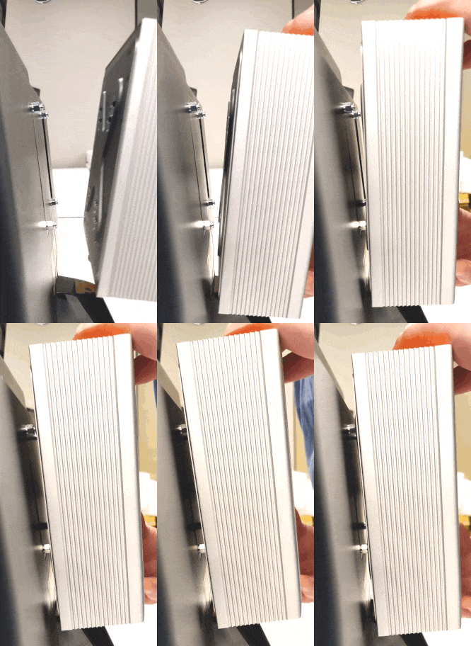
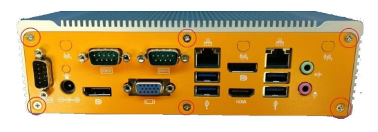
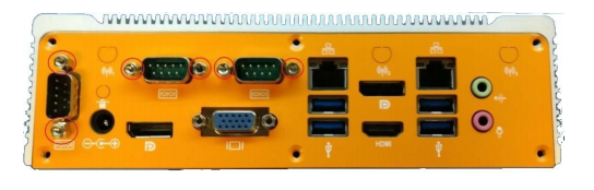
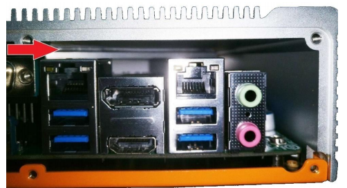
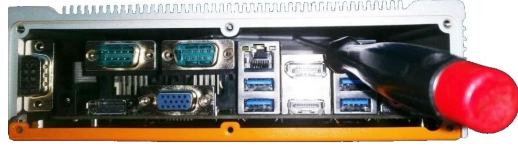
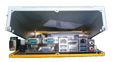
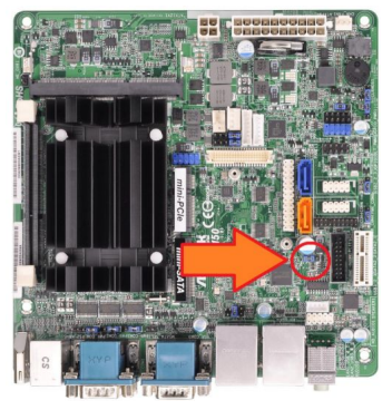
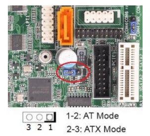
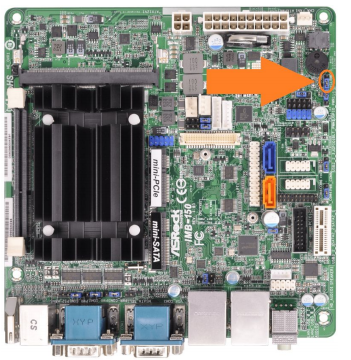
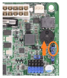
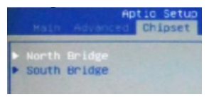
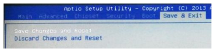
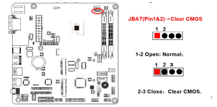
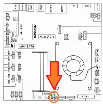
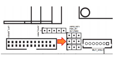
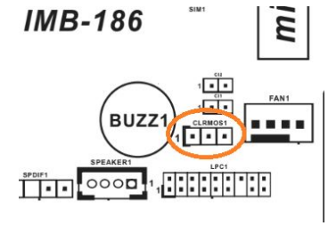
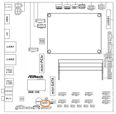
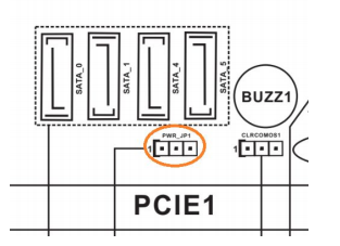
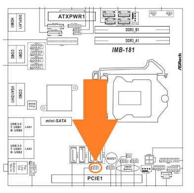
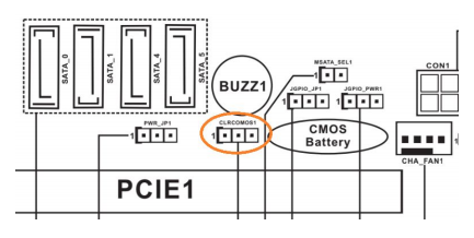
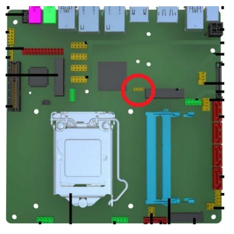
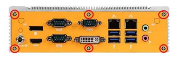
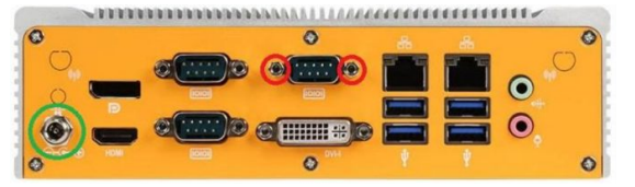
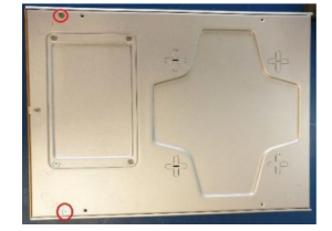
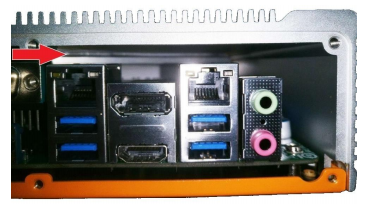
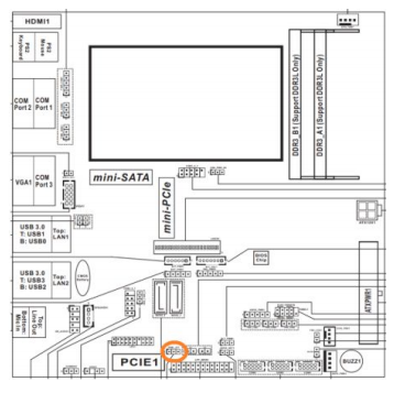
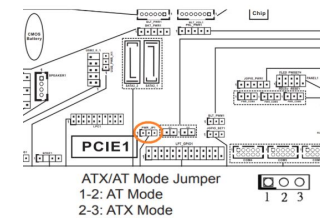
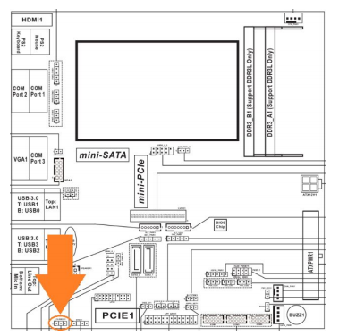
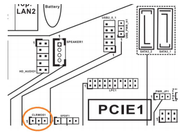
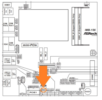
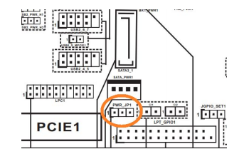
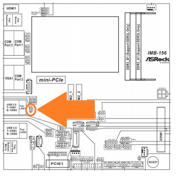
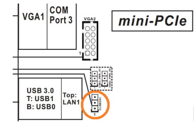
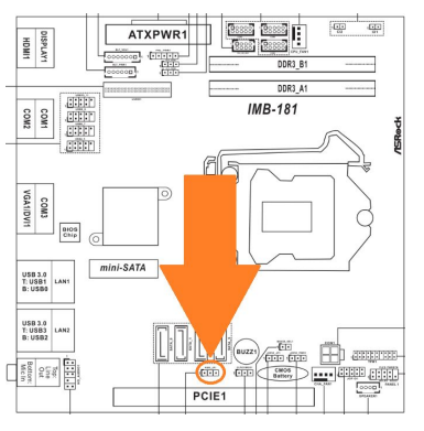
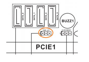
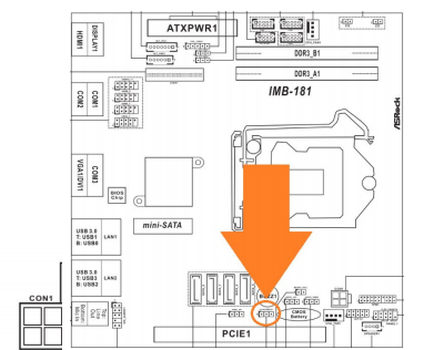
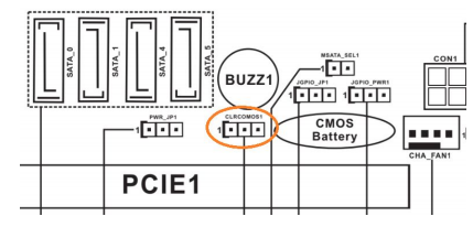
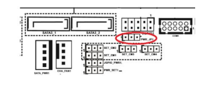
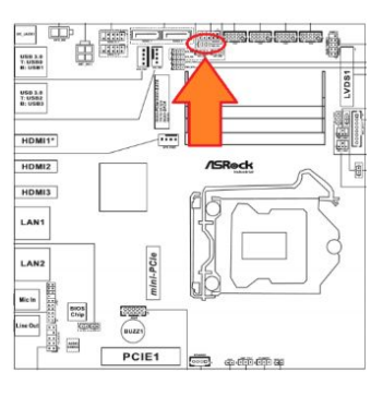
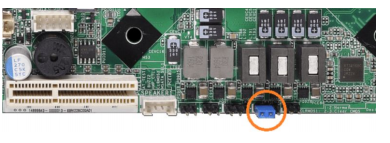
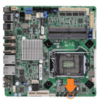
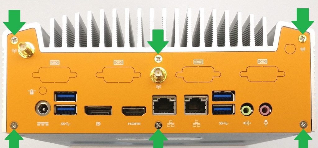
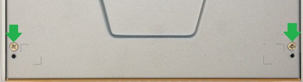
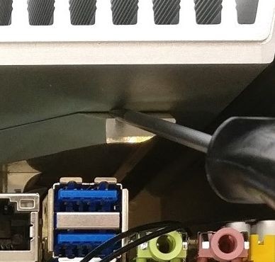
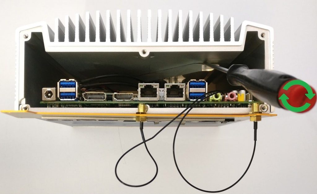
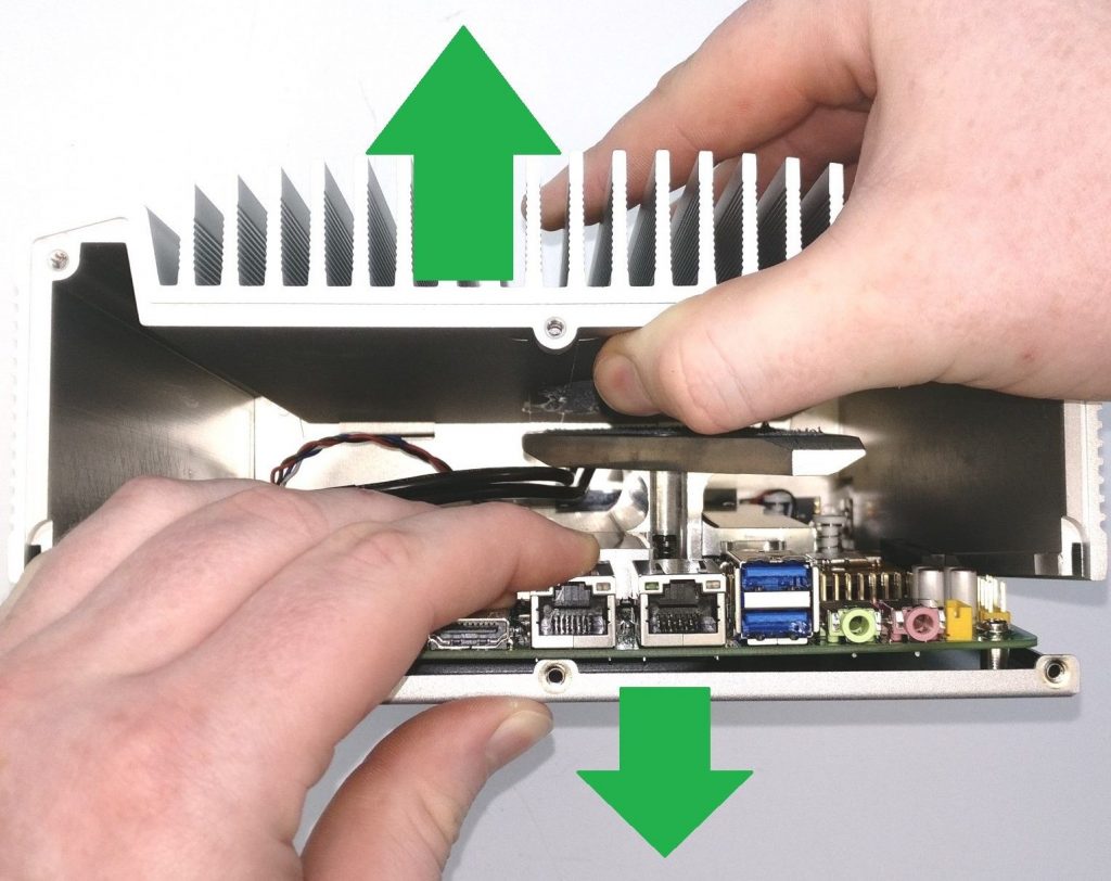
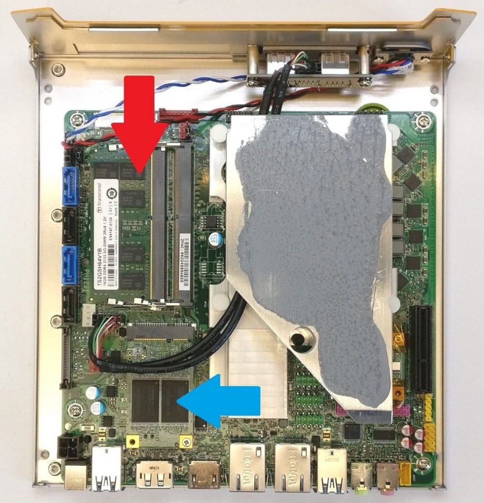
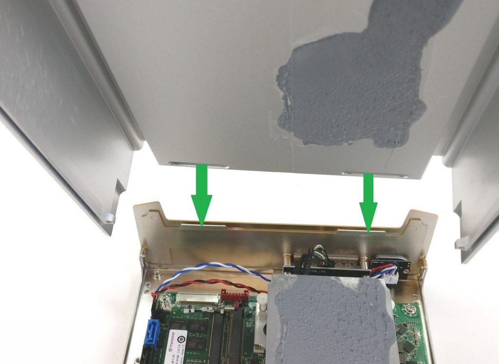
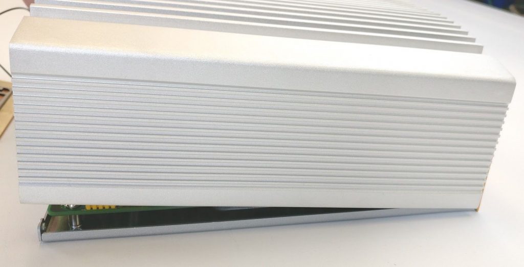
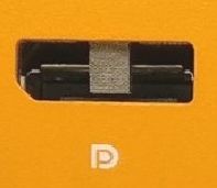
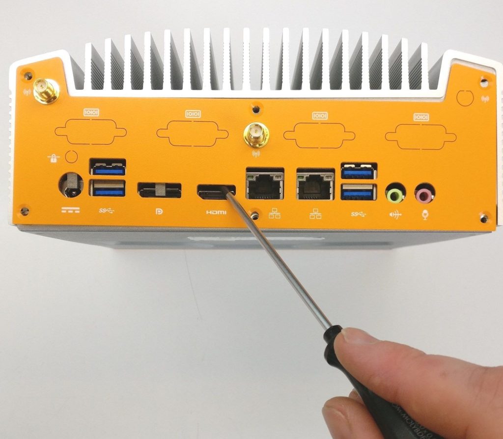
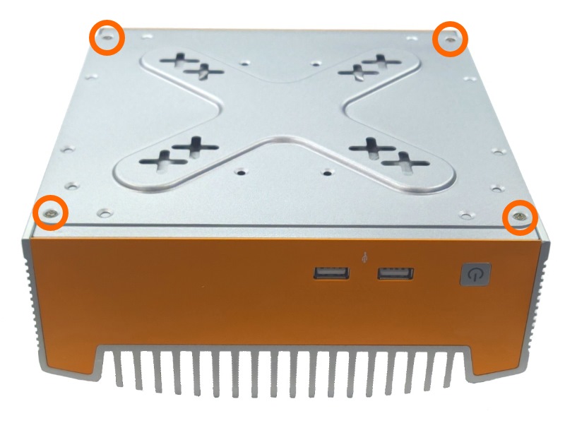
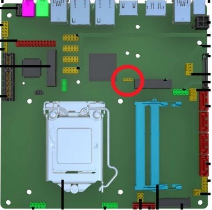
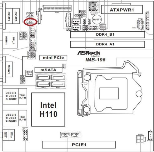
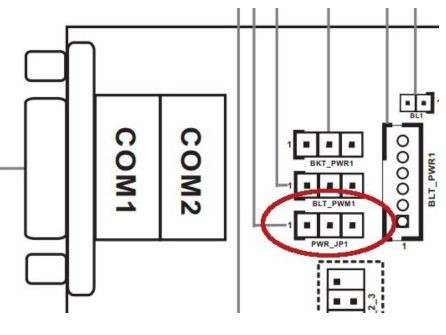
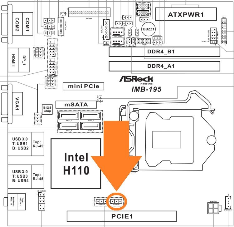
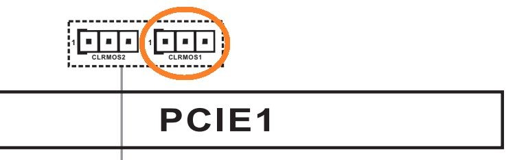
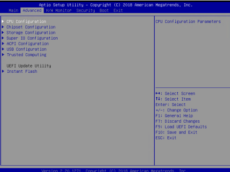
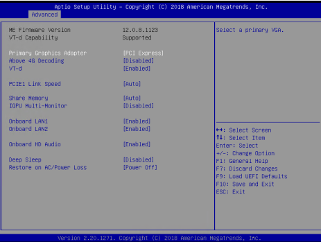
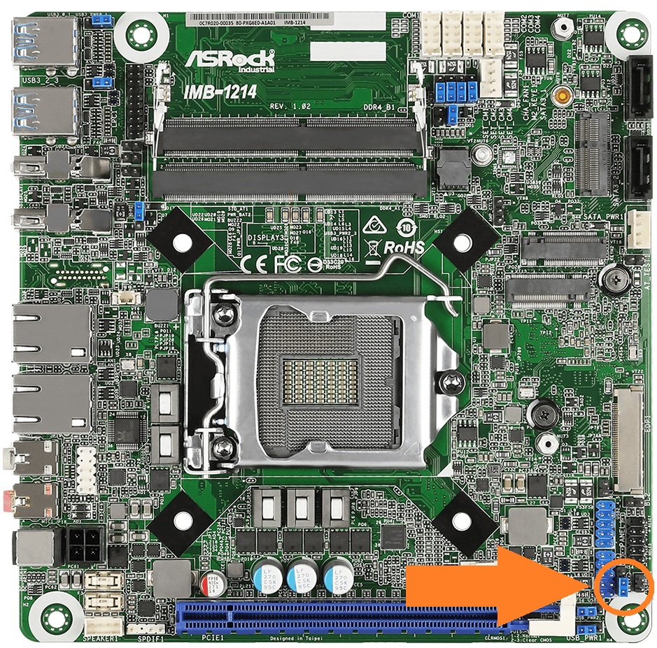
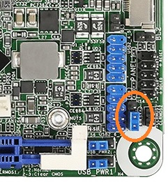


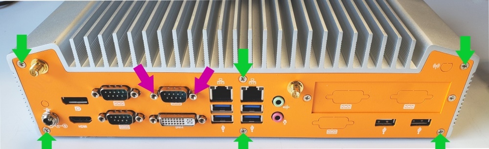
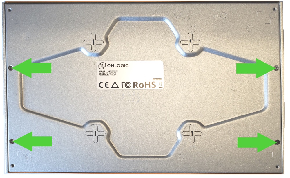
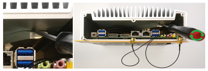
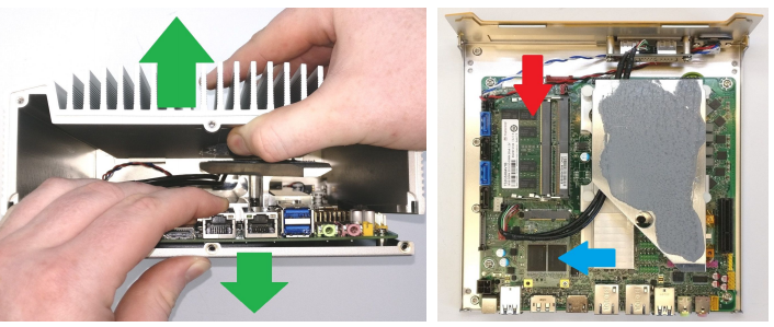
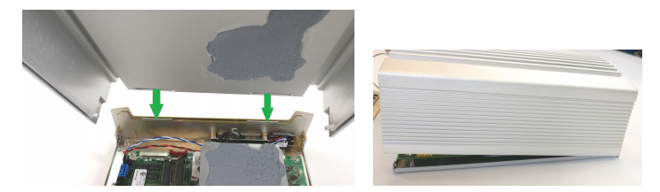
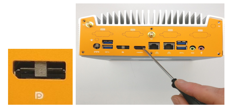
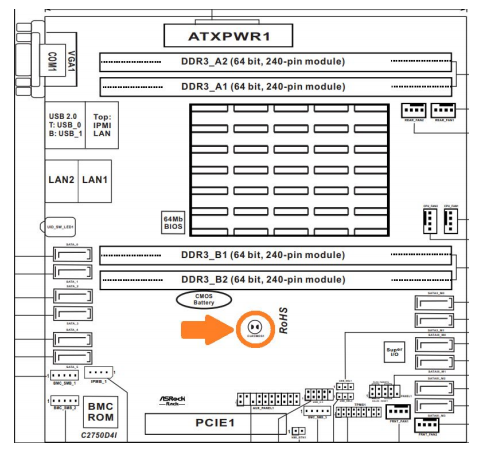
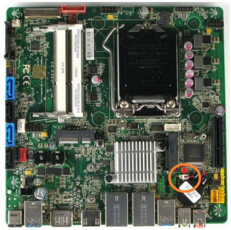
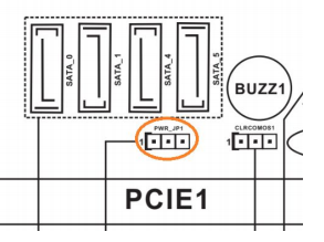
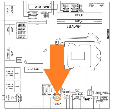
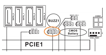
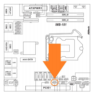
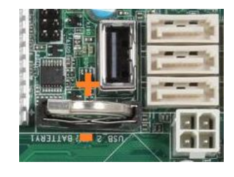
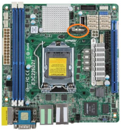
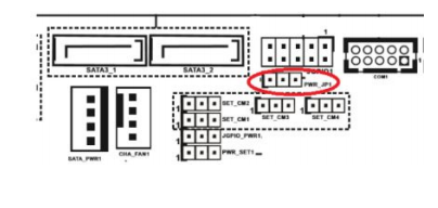

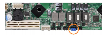
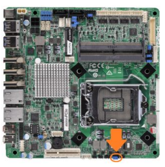
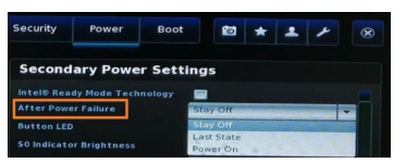
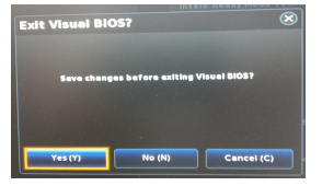
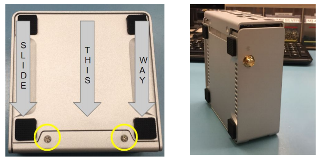
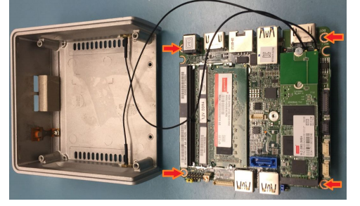
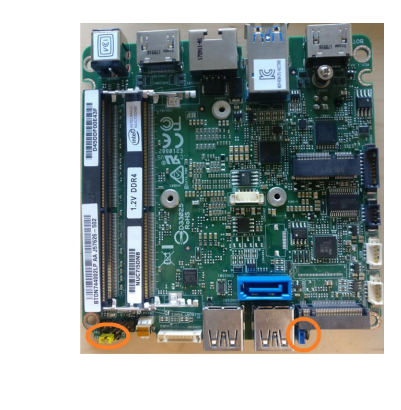

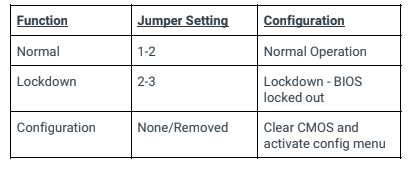
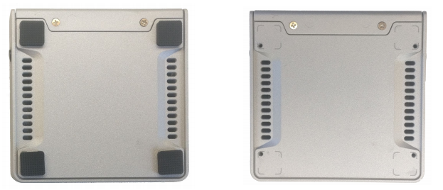
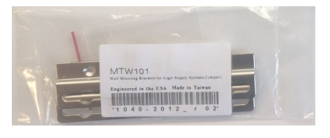
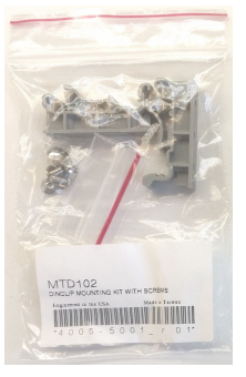
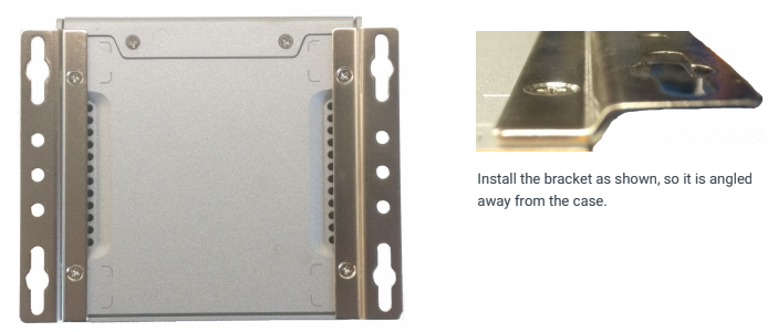
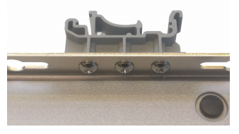
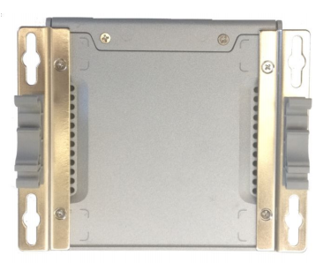
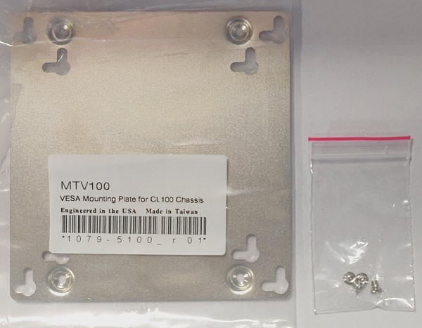
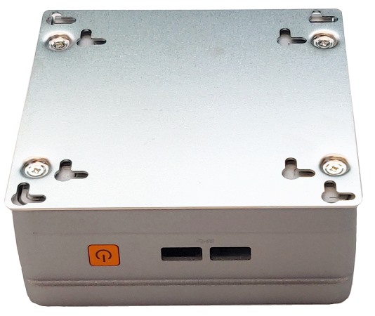
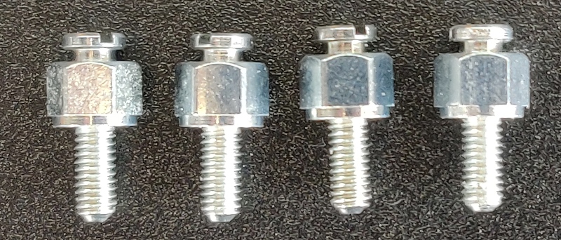
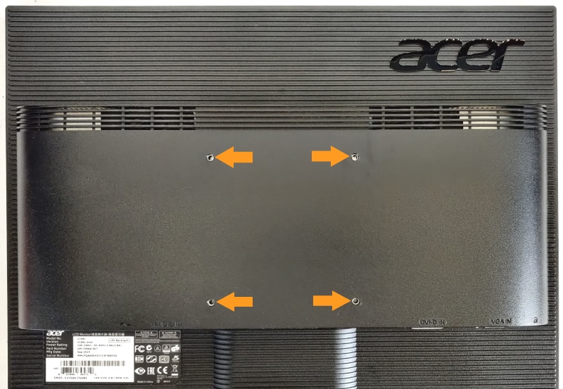
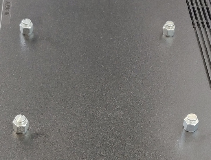
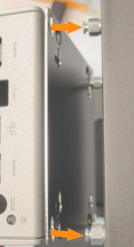
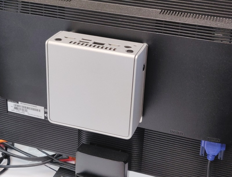
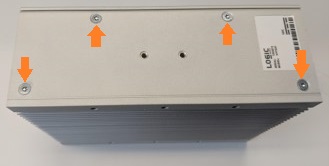

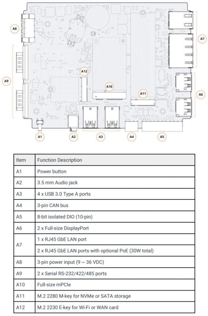
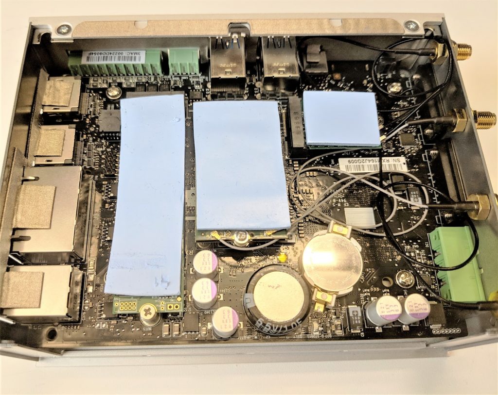

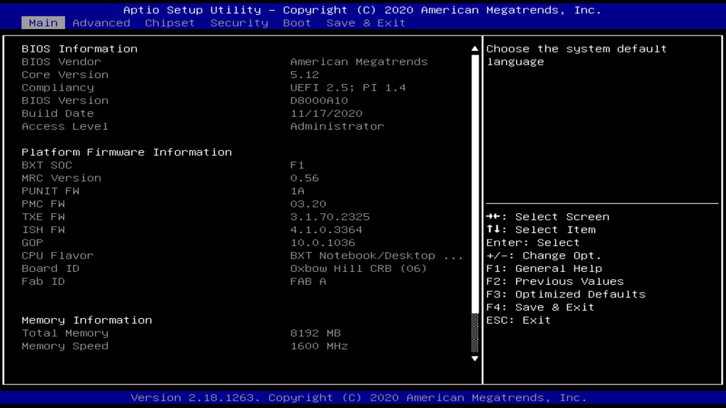
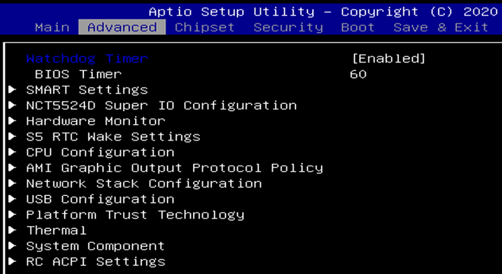
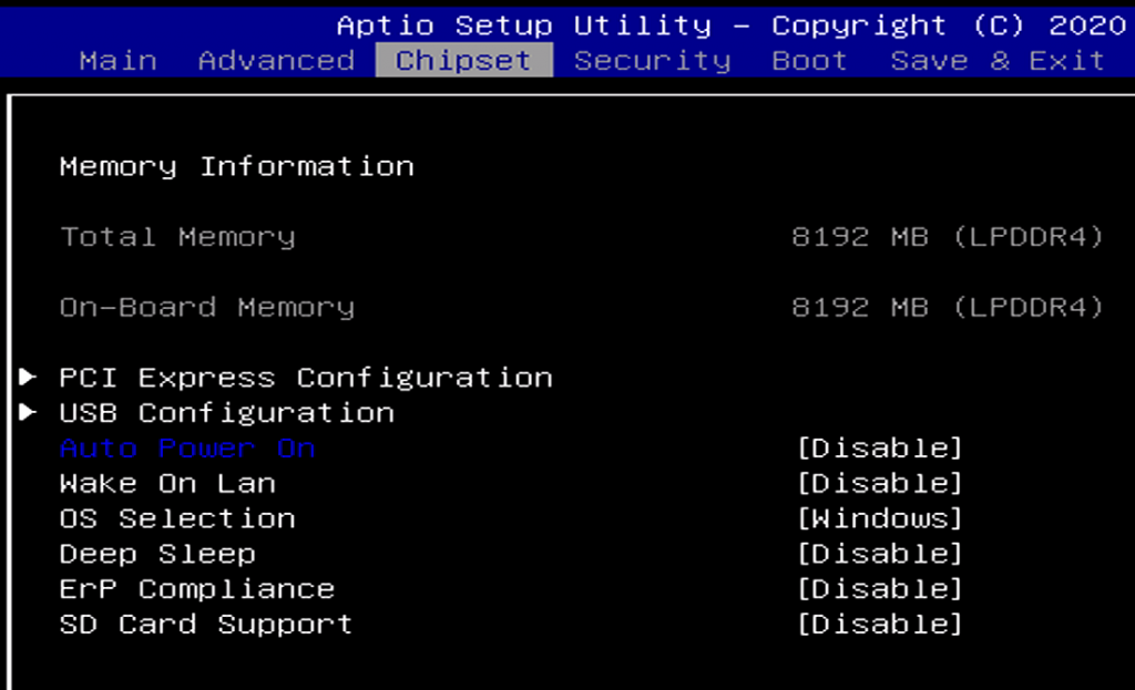
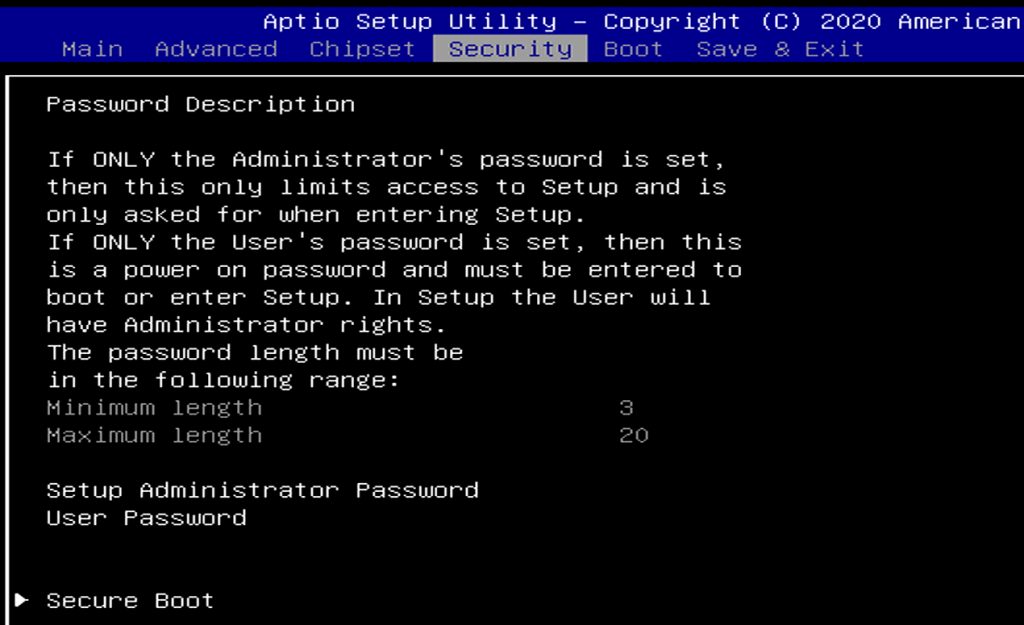
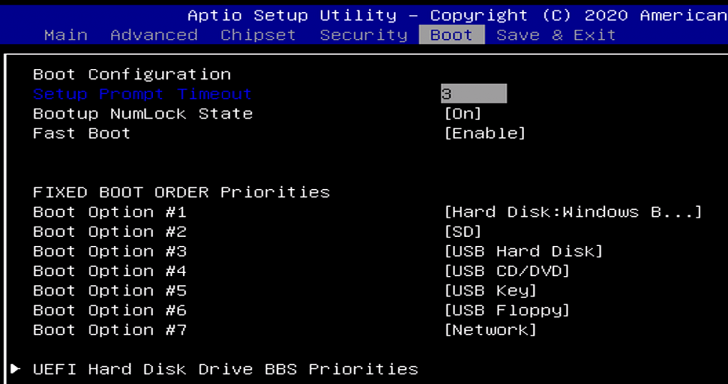
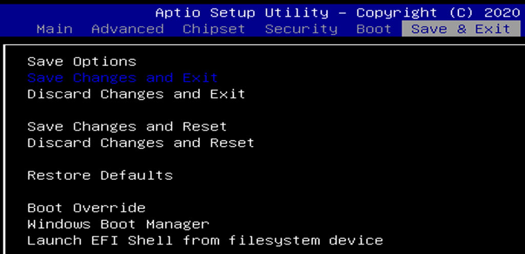
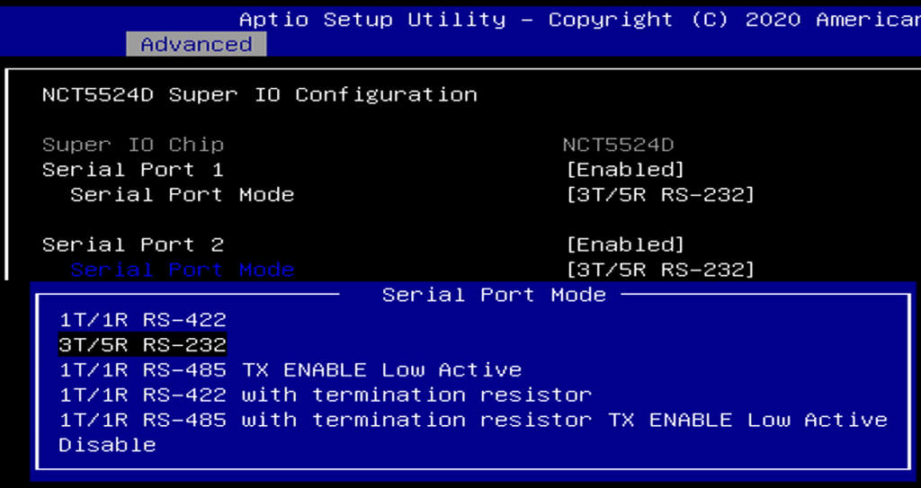
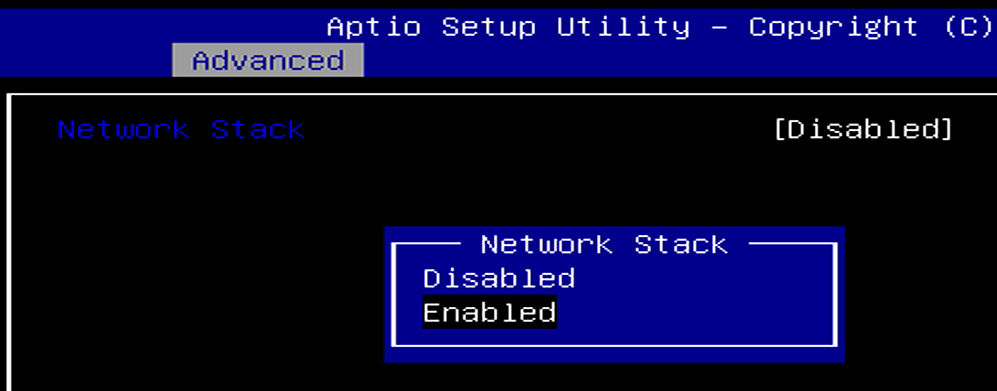
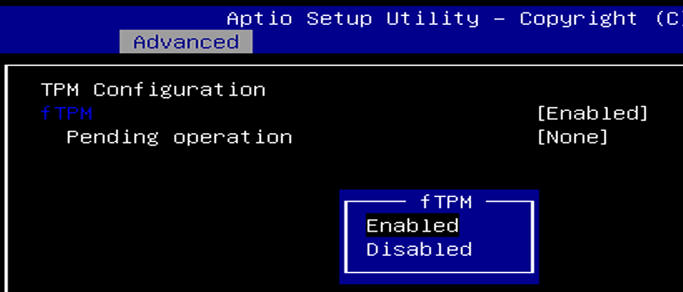
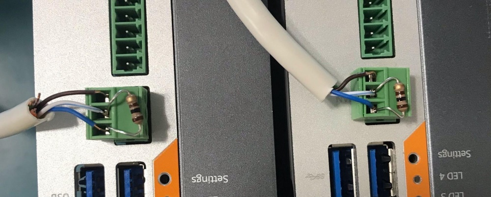
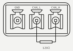
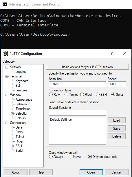

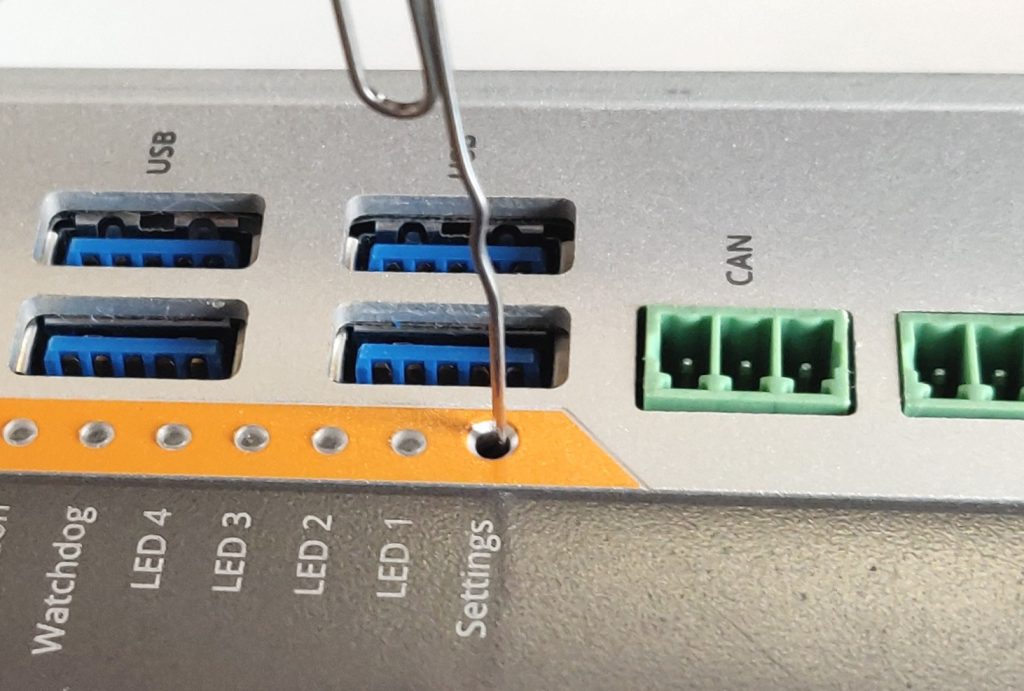
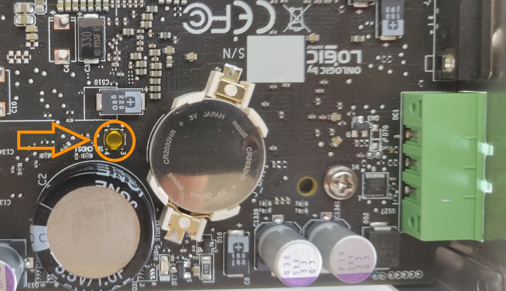
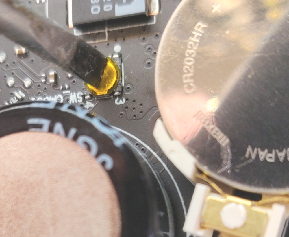


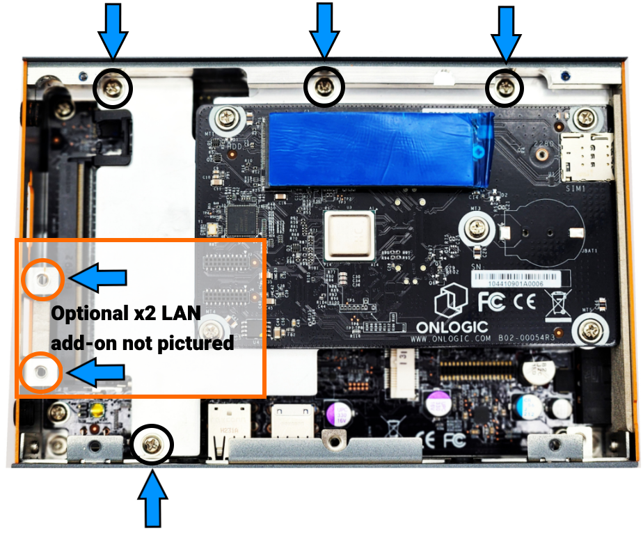

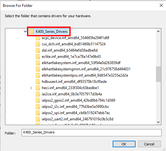

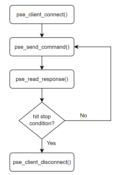


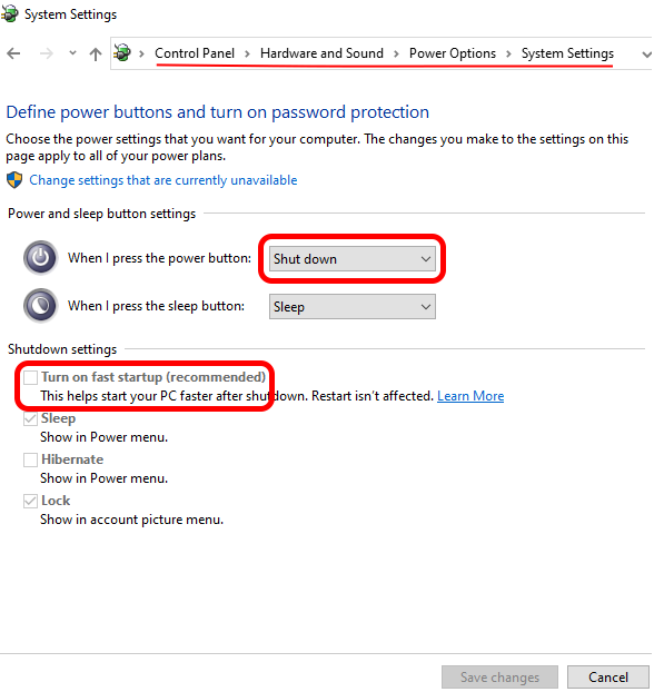


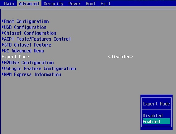
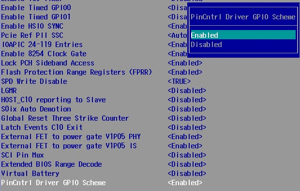

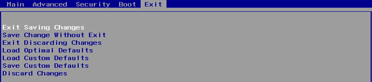
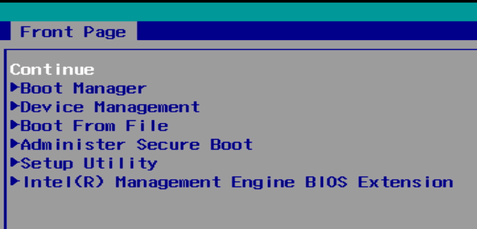
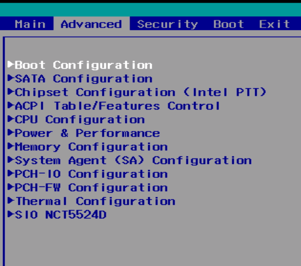
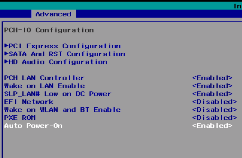
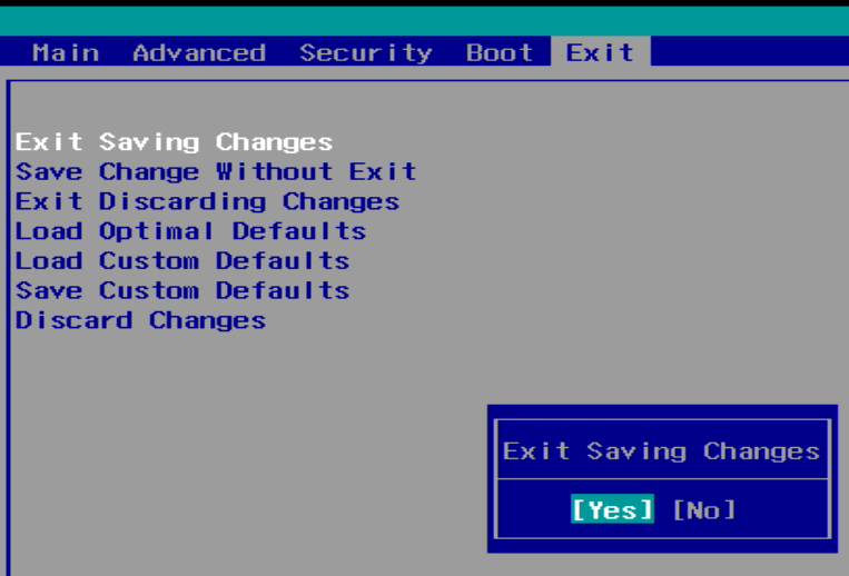
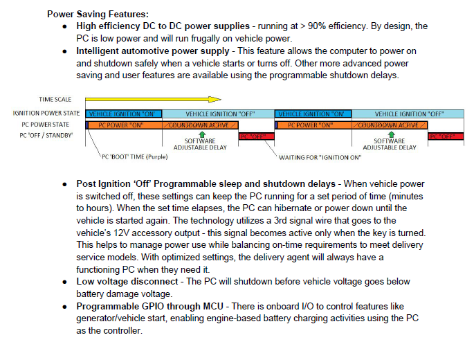
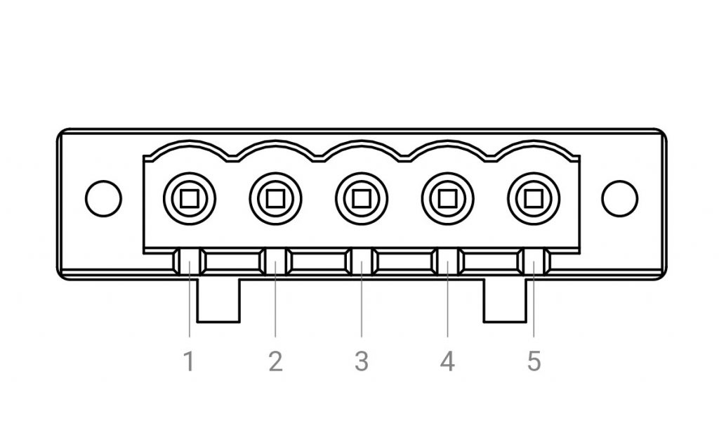
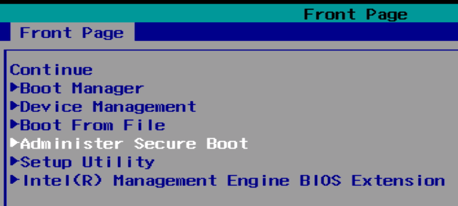
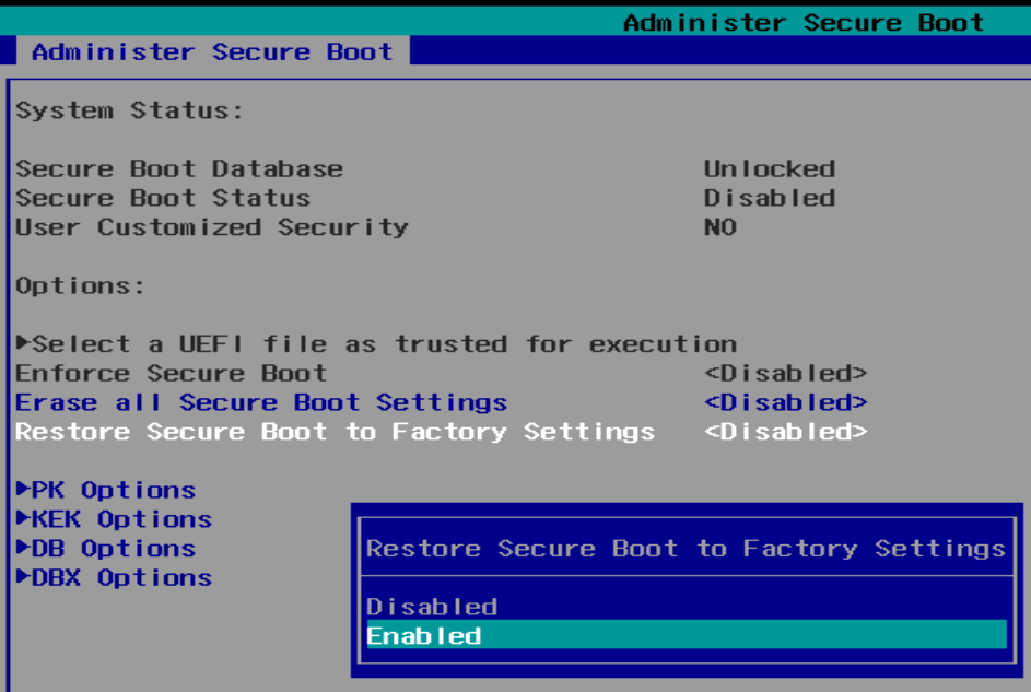
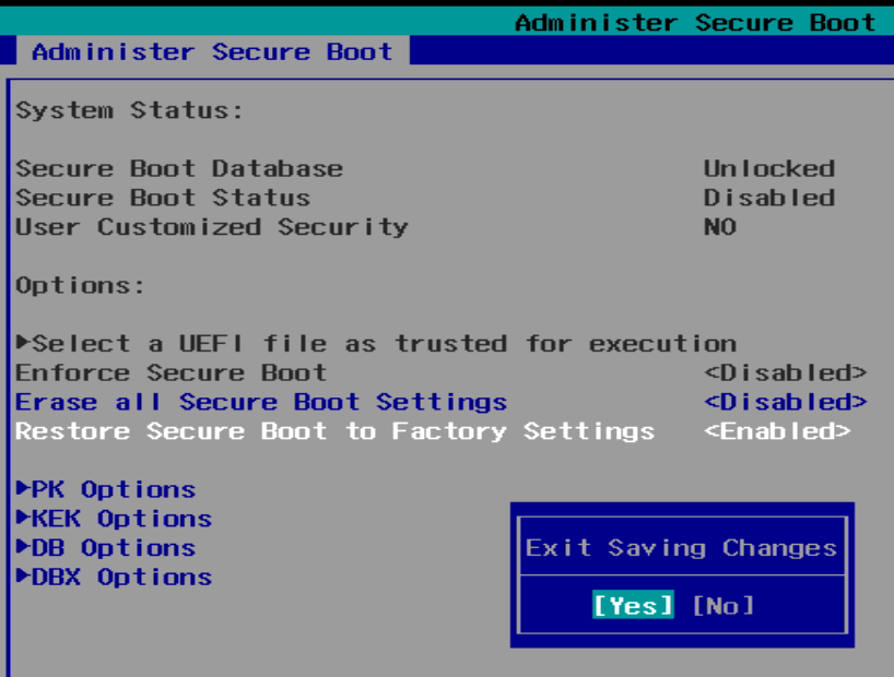
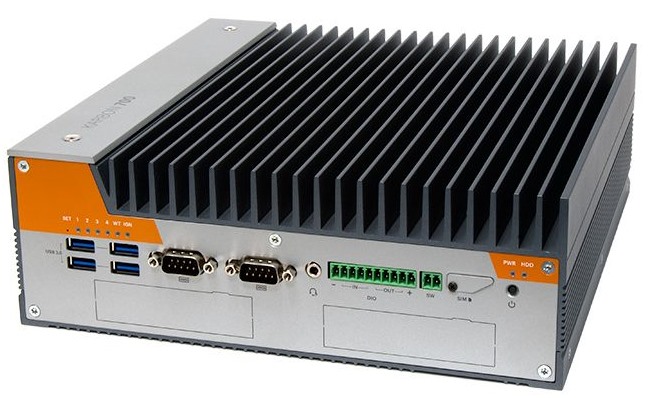
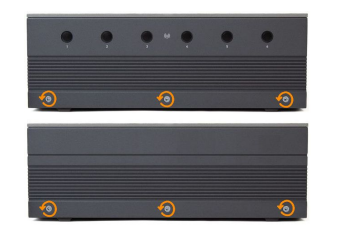
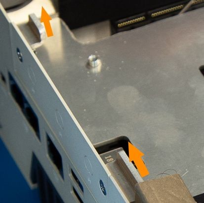
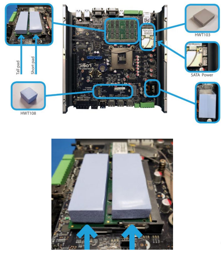
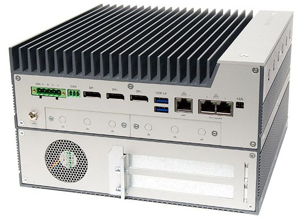
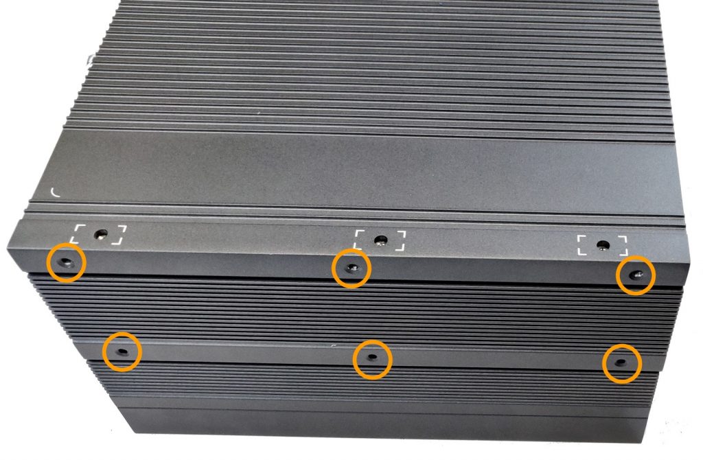
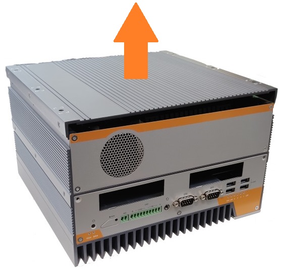
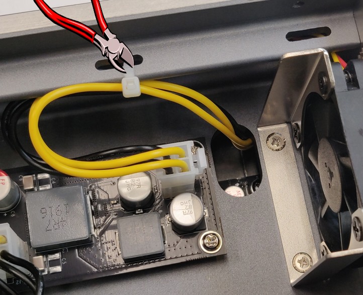
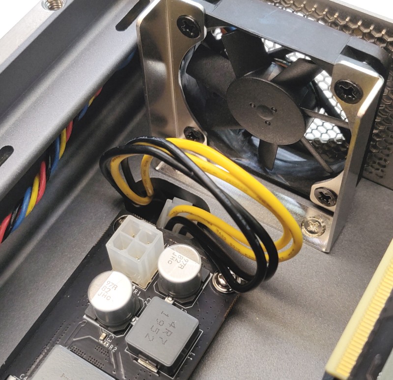
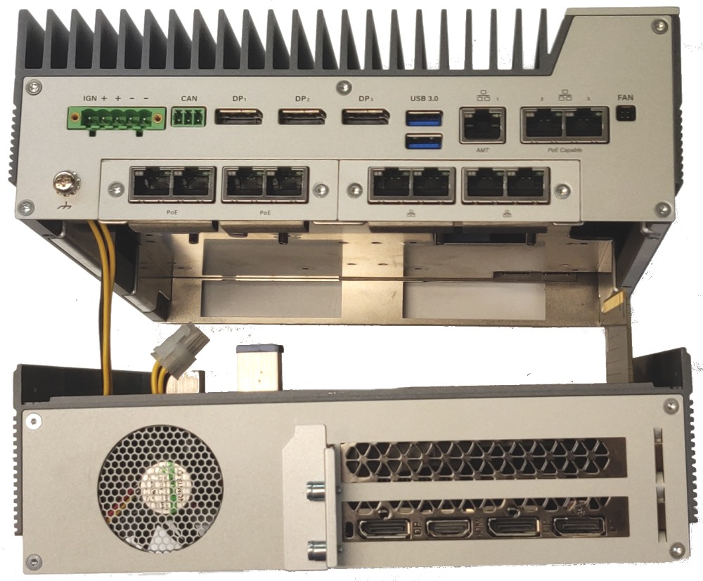
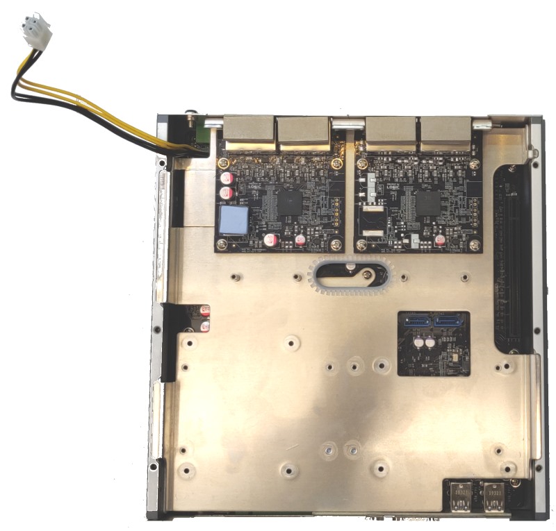
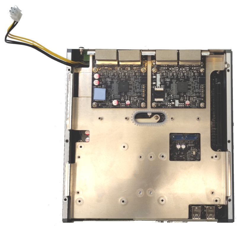
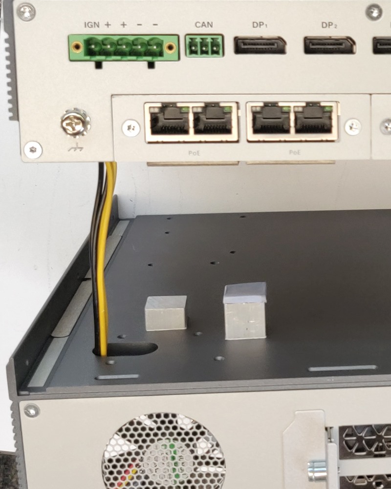
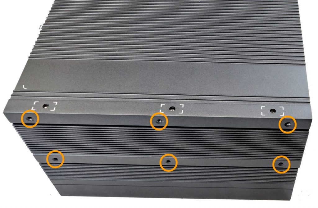
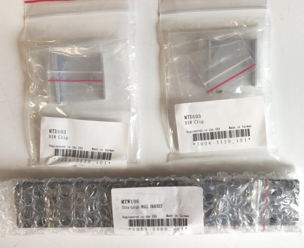
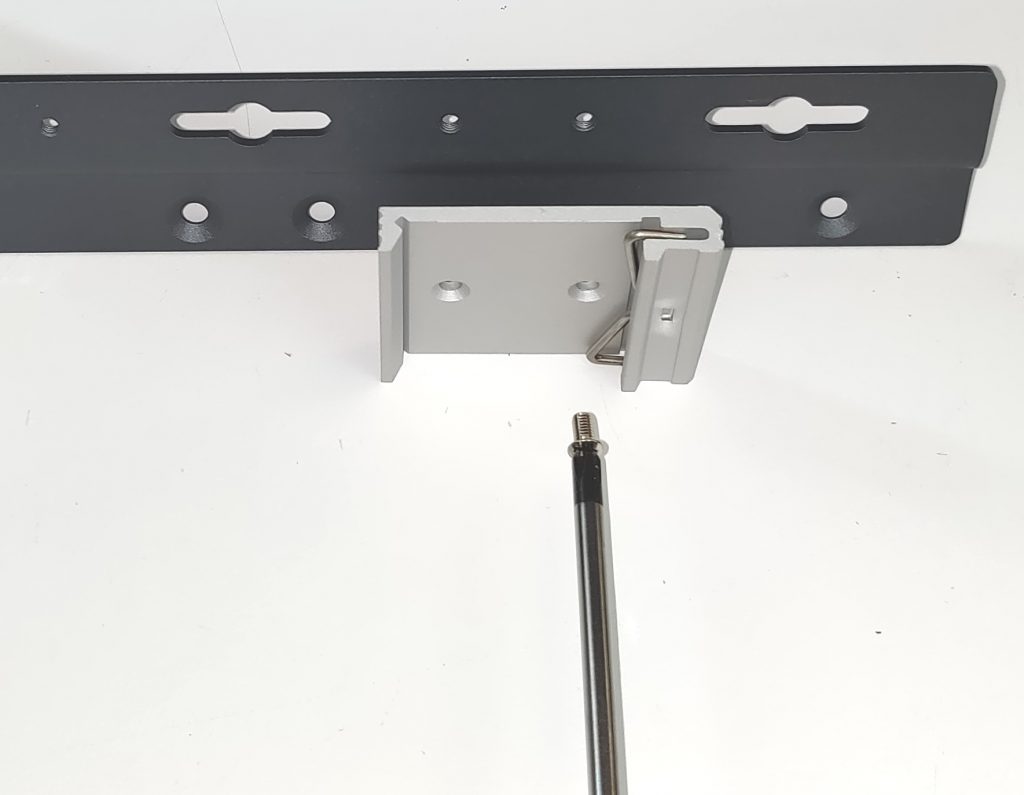
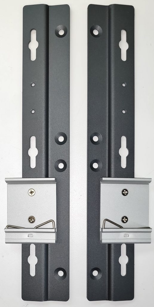
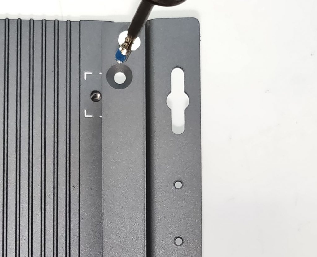
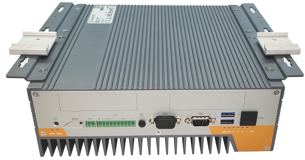
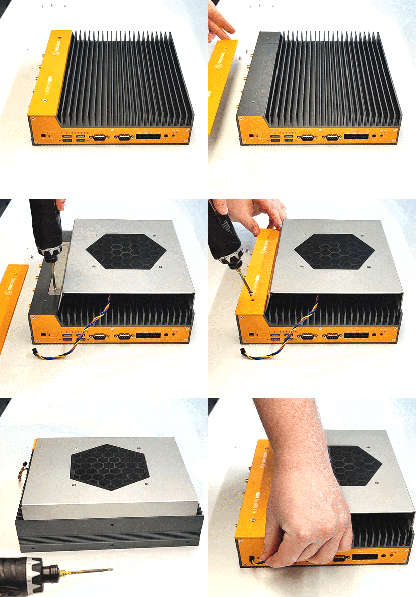
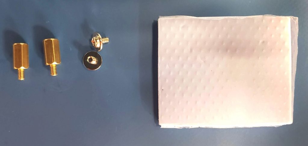
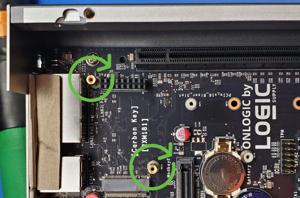
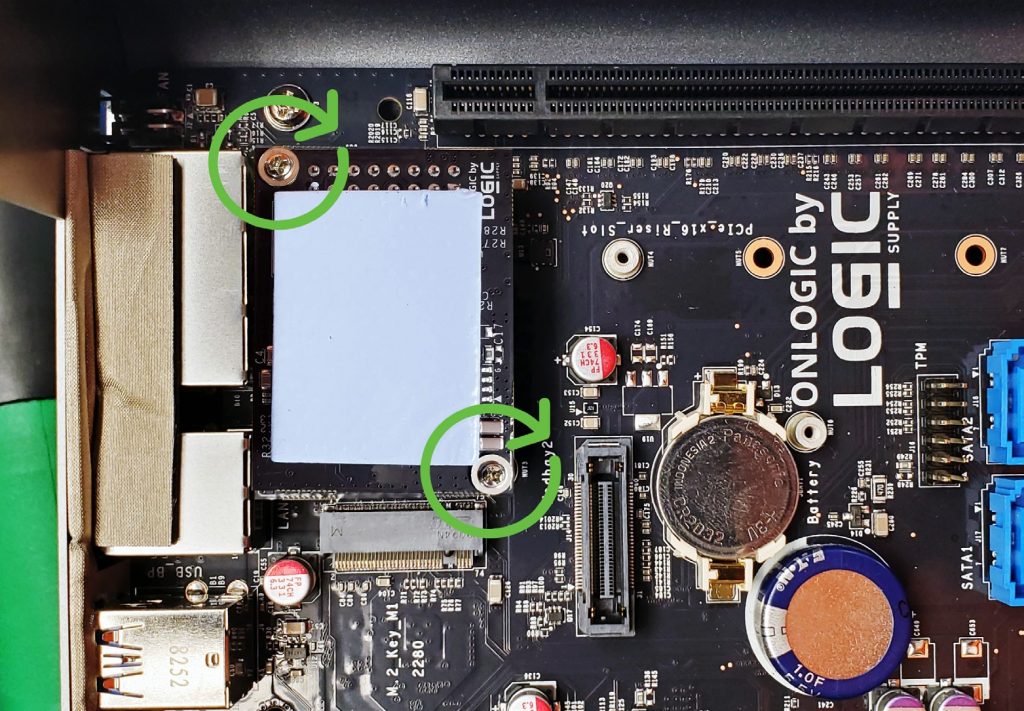
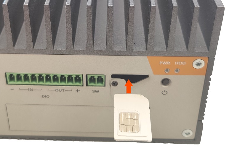
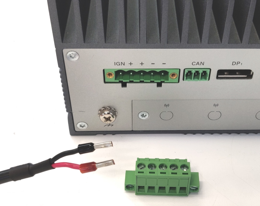
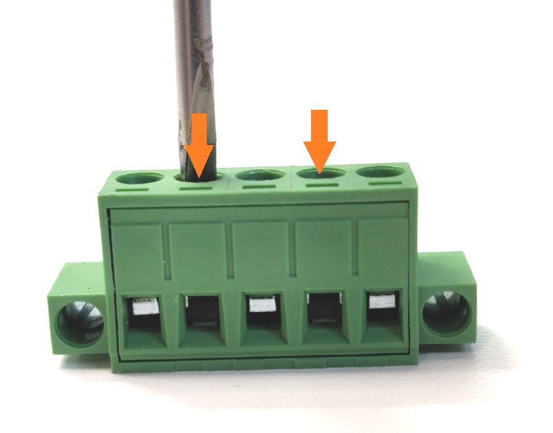
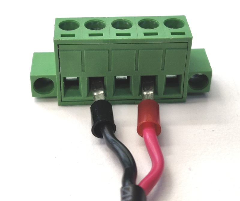
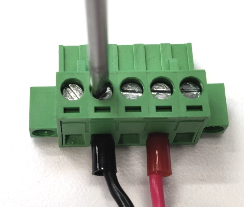
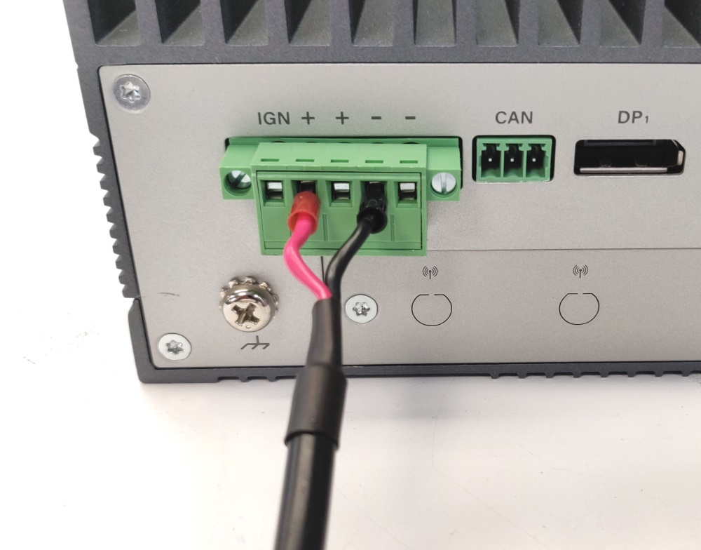
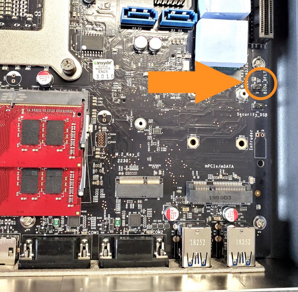
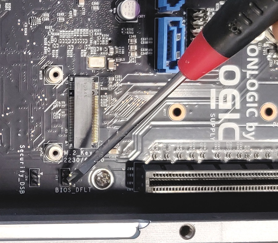
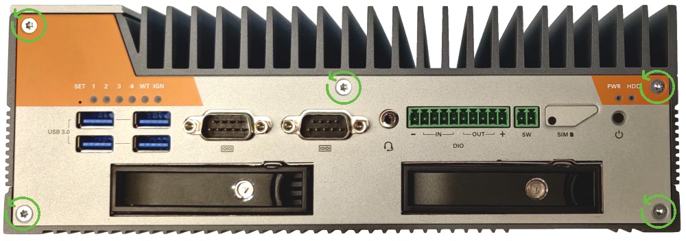
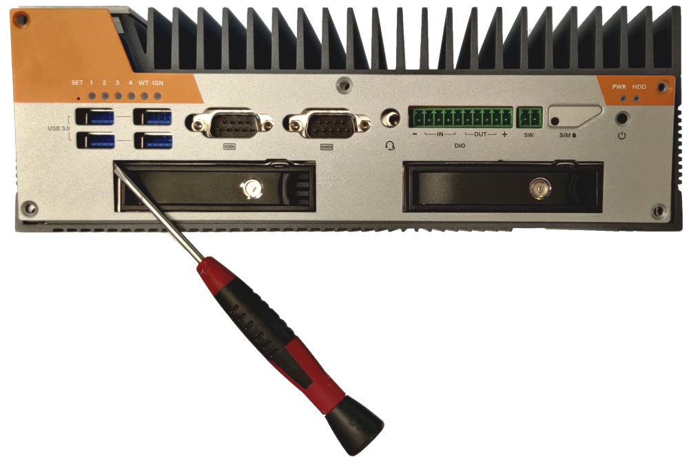
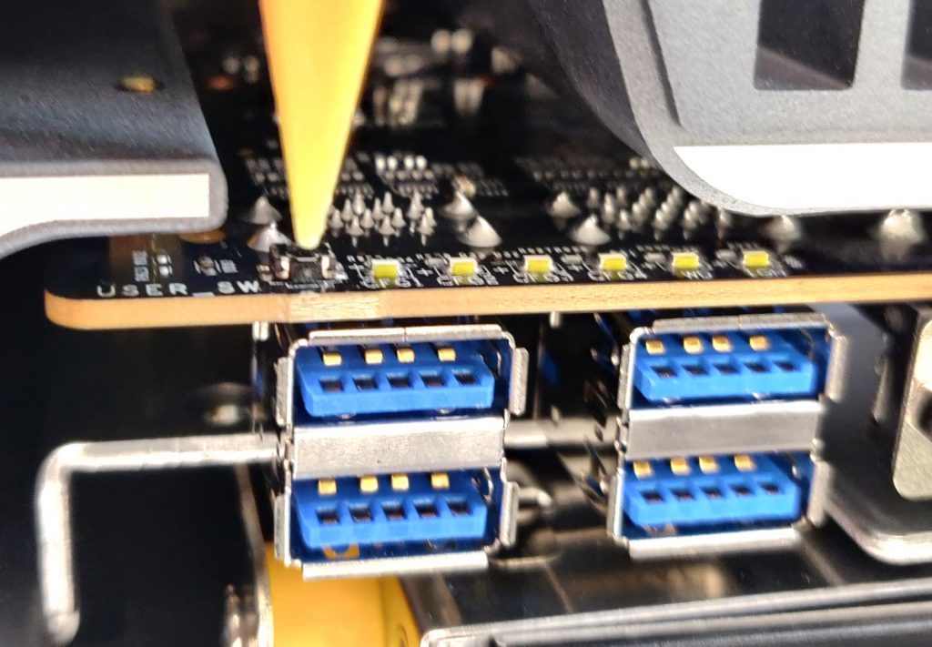
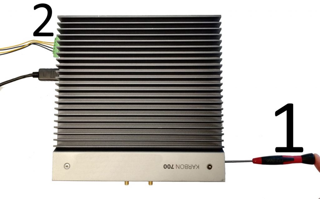
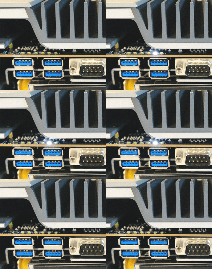
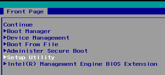
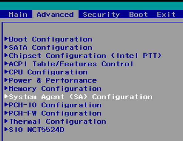
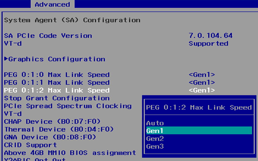

 | FCC 47 CFR Part 15 Subpart B (Class A) |
| --------------------------------------------------------------------------------------------------------------------------------------------------------------------------------------------------------------------------------------------------------- | --------------------------------------------------------------------------------------------------------------------------- |
|
| FCC 47 CFR Part 15 Subpart B (Class A) |
| --------------------------------------------------------------------------------------------------------------------------------------------------------------------------------------------------------------------------------------------------------- | --------------------------------------------------------------------------------------------------------------------------- |
|  |
|  | RoHS 3 (2015/863/EU) |
|
| RoHS 3 (2015/863/EU) |
|  | WEEE Directive (2012/19/EU) |
|
| WEEE Directive (2012/19/EU) |
|  |
|  | Power Immunity According to E-Mark ISO 7637-2 & ISO 16750-2 |
|
| Power Immunity According to E-Mark ISO 7637-2 & ISO 16750-2 |
|  | EN 50121-3-2 |
|
| EN 50121-3-2 |
|  | IEC 60601-1-2, 4th ed. |
|
| IEC 60601-1-2, 4th ed. |
|  | EN 60945, 4th ed. |
## 2- Technical Specifications
### 2.1- External Features
#### Front I/O Definition

#### Rear I/O Definition

#### Serial Ports
The serial ports on the Karbon 800 series motherboard support RS-232, RS-422 Full-Duplex, and RS-485 half-Duplex configurations. The serial port communication mode can be selected in the BIOS configuration. In addition, 5V & 12V power can be enabled on pin 9 in the same BIOS menu. Pin 9 is rated to provide 250mA of current. Refer to the [BIOS manual](/product-documentation/rugged-products/karbon-k800-series/k800-bios-manual) for configuration instructions.
| EN 60945, 4th ed. |
## 2- Technical Specifications
### 2.1- External Features
#### Front I/O Definition

#### Rear I/O Definition

#### Serial Ports
The serial ports on the Karbon 800 series motherboard support RS-232, RS-422 Full-Duplex, and RS-485 half-Duplex configurations. The serial port communication mode can be selected in the BIOS configuration. In addition, 5V & 12V power can be enabled on pin 9 in the same BIOS menu. Pin 9 is rated to provide 250mA of current. Refer to the [BIOS manual](/product-documentation/rugged-products/karbon-k800-series/k800-bios-manual) for configuration instructions.