This article provides specific examples for the K300 and K700 systems. Other models may not be compatible with the exact software packages used. Check out the available documentation directly on your system’s Support page. Checkout the newer generation of the K300 and K700 systems here:
What is DIO?
DIO, or Digital Input/Output, is a simple form of interface used in a wide range of systems to effectively relay digital signals from sensors, transducers and mechanical equipment to other electrical circuits and devices.
Sometimes referred to as General Purpose Input/Output (GPIO), DIO utilizes a logic signal to transfer information. Unlike an analog signal which might be comprised of varying voltages, the digital signals used by DIO have two possible values and are generally represented as either OFF or ON. Think of analog signals as those you might use a knob or dial to set, while digital signals would most often be controlled by a switch. This makes it ideal for sensing switch contacts, reacting to motion sensors, limit switches, operator buttons or machinery status indicators. It can also be used to control indicator lights, small relays or PLCs within equipment.
Read more about DIO basics on our blog.
Tutorial
Prerequisites
Install Python3 and the Pykarbon library.
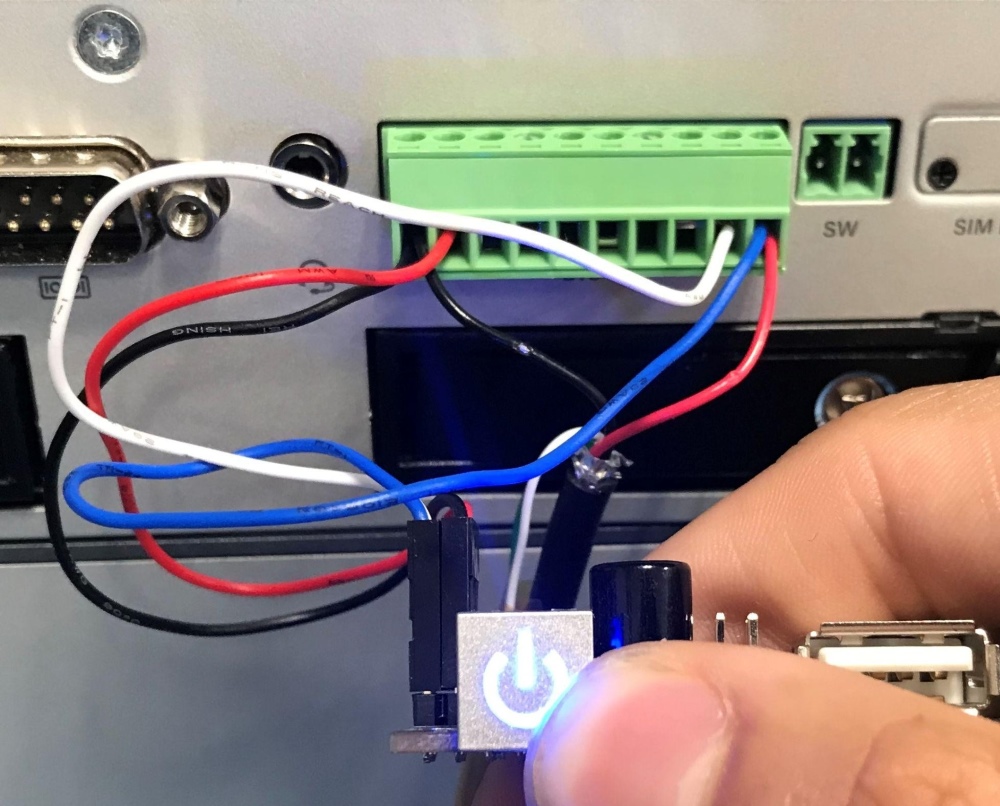
This tutorial will outline a quick and simple test for the Karbon K300 and K700 series’ Digital I/O. We’ll wire the DIO port and run a simple python script to control an LED during a button press event on an input pin
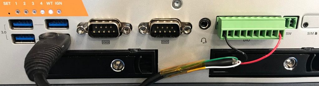
The Karbon Digital I/O port is not powered and will need to have power supplied to the port. The DIO port is able to handle 5-36VDC on the K300 and 5-48VDC on the K700.
For this tutorial we’ll borrow the USB port’s 5V and GND pins and splice a spare USB cable for use in the DIO port.
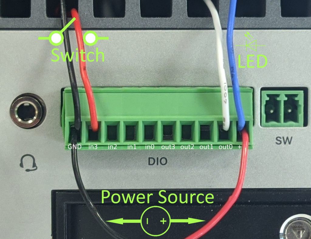
Once the power is supplied to the DIO port we’ll need to wire up our input. Since the Input of the DIO are pulled high when floating, we’ll wire an input to ground so that pressing the button will pull the input low.
We’ll wire up an LED to output 3 and to the supplied 5V. NOTE: most LEDs will need to have a resistor in line from the power rail to limit the current supplied to the LED. check the details of the current limits of the LED you are using.
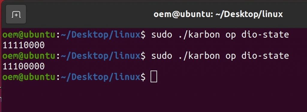
To validate the input is working, the karbon CLI utility can be run to monitor the behavior of the inputs and outputs.
Running the karbon tool with the `op dio-state’ will print out what the input and output states are. The output bit order is I0 I1 I2 I3 O0 O1 O2 O3
Since we have the button wired to Input 3 we should expect 11110000 and then 11100000 when the command is ran while the button is pressed.
Now that that input can be read from the MCU, the output portion can be configured.
We can run a python script that will react to Input 3 being pulled low with the button press and set output 3 to high and turn the LED on.
Save the following script as dio.py and run it with the command python3 dio.py
import pykarbon.terminal as pkt

def callback_fn(arg):
    if arg[3] == '0': #check if 3rd item from popdata() is 0
        print("DI 3 --> LOW ", arg)
        return True #return True to dev.set_do. sets output high
    else: #if 3rd item from popdat() is anything other than 0
        print("DI 3 --> HIGH", arg)
        return False #return Flase to set_do. sets output low

i = 0

with pkt.Session() as dev:
    dev.update_info(print_info=True) # Update and print configuration info

    dev.set_do(0, False) # Set digital output zero low

    while True: #create loop that runs forever
        line = dev.popdata() #popdata will print out data in the queue
        if line:
            dev.set_do(0, callback_fn(line)) #returns data from queue as argument for use by callback_fn
Running the script will show configuration info and then print out information when the button is pressed and depressed.
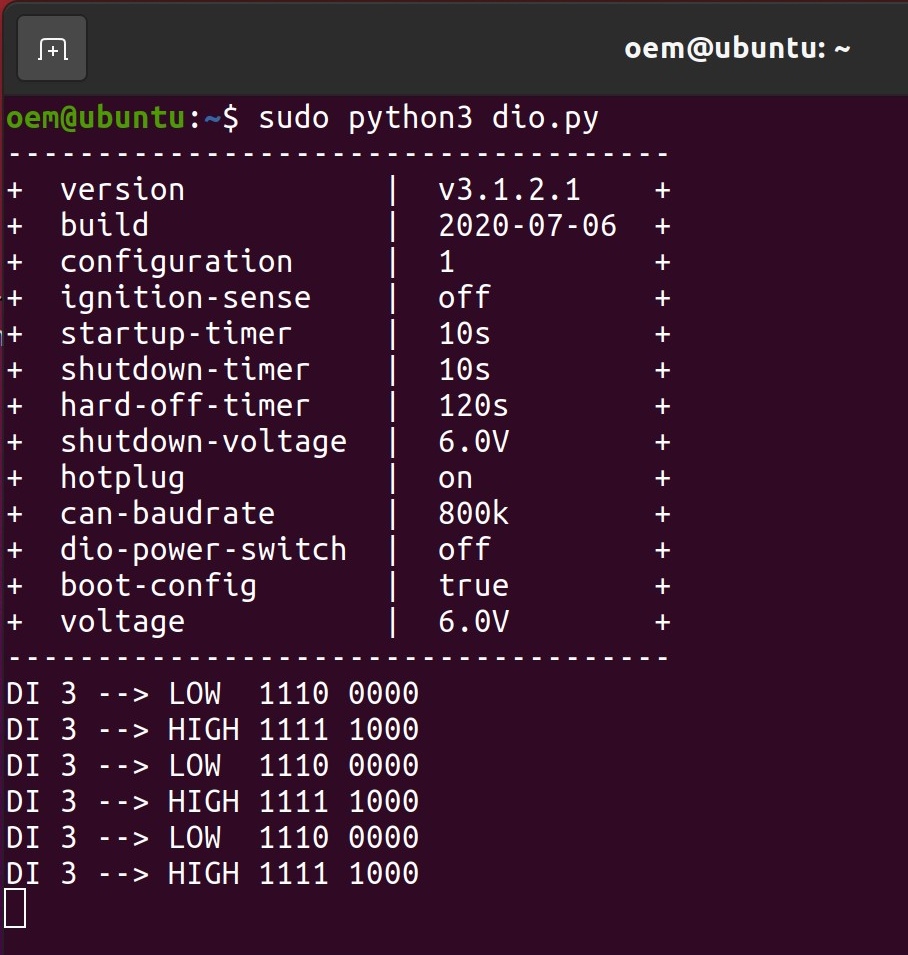
The button press will set input 3 to high, triggering the python script to set output 3 high and turn on the LED.