Documents and Downloads
Spec Sheets & Dimensional Drawings: K801 / K802 / K803 / K804
Drivers
K800 Windows 11 Drivers ( or INF files for server deployment)
K800 Windows 10 Drivers (Follow our guide for Installing via Device Manager)
BIOS Updates
| Bios Version | Link |
|---|---|
| B005 | Download |
You can check the current BIOS version of your system within the BIOS itself. Navigate to:
Setup Utility -> Press Up to show the current BIOS version
Microcontroller Updates
| Microcontroller Version | Changelog | Link |
|---|---|---|
| v1.3.1.2 | – CANbus fixes: Fully reset CAN peripheral when bus is opened, fixes unresponsive interfaces | Download |
Power Sequence Microcontroller Updates
| Microcontroller Version | Changelog | Link |
| v2.1.6 | – Ignition Fixes | Download |
Frequently Asked Questions (FAQ)
How do I enable auto power on?
Enter the BIOS and go to Advanced > PCH-IO Configuration > State After G3. Set it to [s0 State]. See below for a step by step guide.
How do I configure RAID?
Follow our RAID setup guide here:
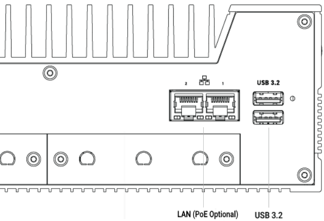
Which LAN ports support PoE?
The K800 can be configured with optional PoE hardware, adding PoE functionality to existing ports, or adding additional PoE ports. Check your configuration to see if your unit has PoE installed.
The optional PoE module supports the 802.3at standard @ up to 25.5 watts per port.
PoE can be added to the native Ethernet ports on either ports 1 & 2 (on the x2 LAN models), or ports 2 & 3 (on the x6 LAN models). Additional ports may be added with the Karbon Modbay cards.
K800 series 2-LAN model:
K800 series 6-LAN model:

What Operating Systems are supported?
Windows 10 IoT 2021 and Windows 11 are supported. In most applications it is NOT necessary to disable the e-cores.
The K800 also supports Ubuntu 22.04 for Intel IoT with Kernel version 5.15. Other Ubuntu and Kernel versions are not supported on the K800 series.
What chipset do the Ethernet ports uses?
The onboard LAN ports use the I225. The optional 10gig Modbay expansion card uses the X550.
What Baudrate is supported on the K800 COM ports?
The K800 series supports up to 115200 baudrate on the COM ports. Higher baud rates can be achieved by implementing the CAN port. See how to do this through the Embedded Microcontroller MCU.
How do I disable TurboBoost on the CPU?
TurboBoost can be disabled in the BIOS of the system. Navigate to Advanced and set Expert Mode to Enabled. Then, go to:
Power & Performance -> CPU – Power Management Control -> Boot Performance -> Set to Max Non-Turbo Performance
How do I enable the external SIM slot?
The K800 series can be configured with an internal modem, the AMIT series modems. If configured with a SIM card, this would be installed internally, directly on the modem. However the modem can be configured to use the external SIM slots to allow easier switching by users. It is recommended to configure the following BIOS setting to enable both external SIM slots:
Setup Utility -> Advanced page -> PCH-IO -> OnLogic Feature Configuration -> SIM Card Muxing -> Set to “Mode 4“
Make sure to Save & Reset via the F10 function key or through the Exit page.
How do I use the integrated video ports, instead of the GPU?
The K800 series can be configured with a GPU. For some customers this is used to drive multiple high-resolution displays, and the video output will automatically output through the GPU. However in some cases you may want to use the GPU for specific computational applications, and use the integrated DisplayPorts. To enable this option, you will want to change the “Primary Display” output in the BIOS. Navigate to:
Setup Utility -> Advanced page -> Set “Expert Mode” to Enabled
Then go to:
Setup Utility -> Advanced -> System Agent (SA) Configuration -> Graphics Configuration -> Primary Display -> Change to “IGFX”
Make sure to Save & Reset via the F10 function key or through the Exit page.
Connecting the power supply
If you need to assemble the system’s power input connector, follow these steps to locate and wire the correct parts.
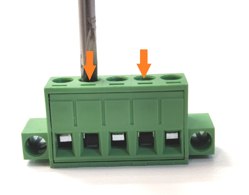
- Unbox the power brick and grab the 5 pin green/black terminal block from the accessory box.
- Using a flathead screwdriver, turn the two indicated screws counter-clockwise a few turns.
- The metal holes at the bottom will open up.
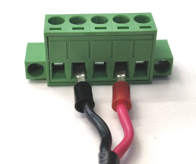
- Insert the power supply wires as shown
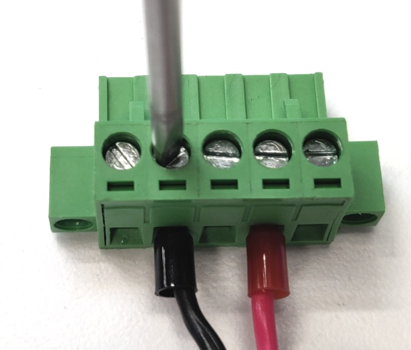
- Turn the screws clockwise to tighten. Firmly hand tighten.

- Connect the green/black terminal block to the K800. It is now ready for use. Note that the labeling on the back of the system matches the wires you just installed.
Enabling Auto Power On
The K800 can be configured to turn on automatically when DC power is connected. This is useful for power outage recovery or if the unit is mounted in a hard to reach location. You can enable Auto Power On by following the steps listed below.
- Note: In future revisions the name of this setting will be changed. “Auto power ON’ under the Power tab will be the new name and location.
- Power on the system and press Del a few times to access the “Front Page” menu
- Choose “Setup Utility”
- Navigate to Advanced > PCH-IO Configuration

- Locate “State After G3”
- Change it to”s0 State” to enable auto power on.
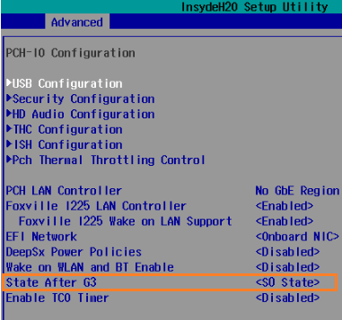
- Press F10 to Save & Exit
Disassembly
K801 Disassembly
Opening the system does not void the manufacturer’s warranty, however, some precautions are necessary to avoid damaging the unit. Damage caused while opening or modifying the system internals may not be covered by the warranty.
- Perform this disassembly in an area free of static discharge
- Before beginning, touch a grounded metal surface to discharge your body of static electricity
- Turn the unit upside down and remove the 6 screws from the bottom plate.
- Pry the bottom plate off
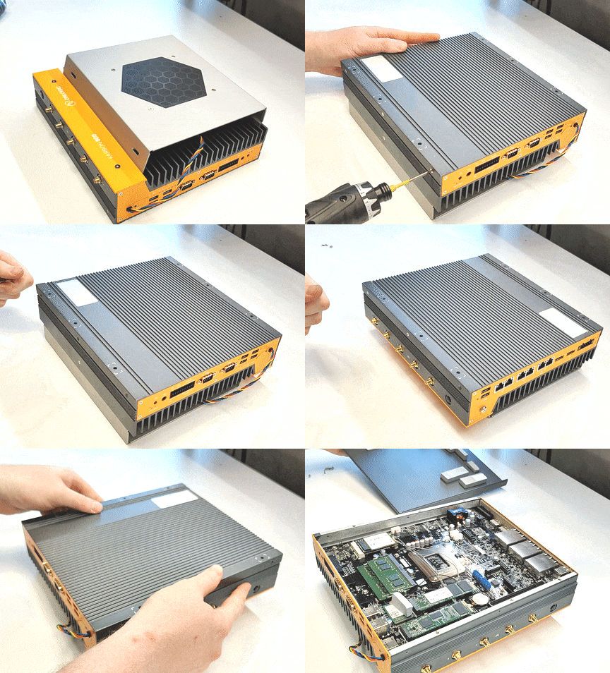
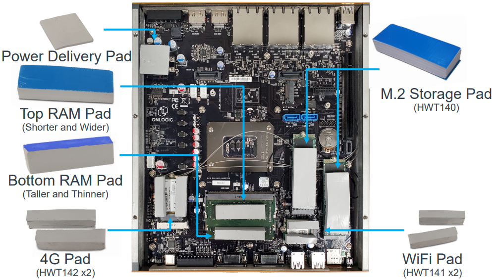
- In case the thermal pads become displaced during disassembly, a reference guide is shown below. Note that the blue film will not be present as it is removed during initial assembly.
K802 Disassembly
Opening the system does not void the manufacturer’s warranty, however, some precautions are necessary to avoid damaging the unit. Damage caused while opening or modifying the system internals may not be covered by the warranty.
- Perform this disassembly in an area free of static discharge
- Before beginning, touch a grounded metal surface to discharge your body of static electricity
- Turn the unit upside down and remove the 6 screws from the bottom plate.
- Pry the bottom plate off

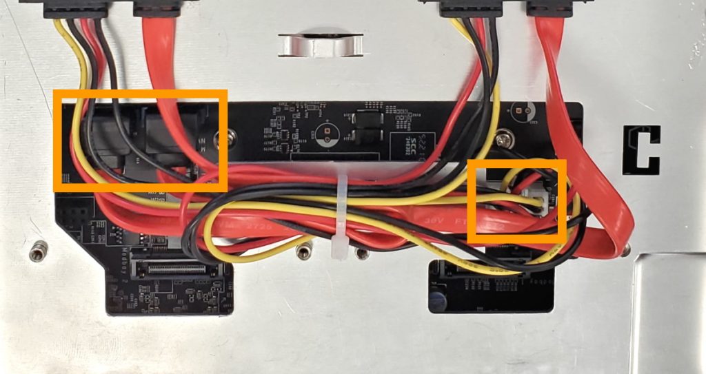
- Unplug the SATA power and data cables (if equipped)
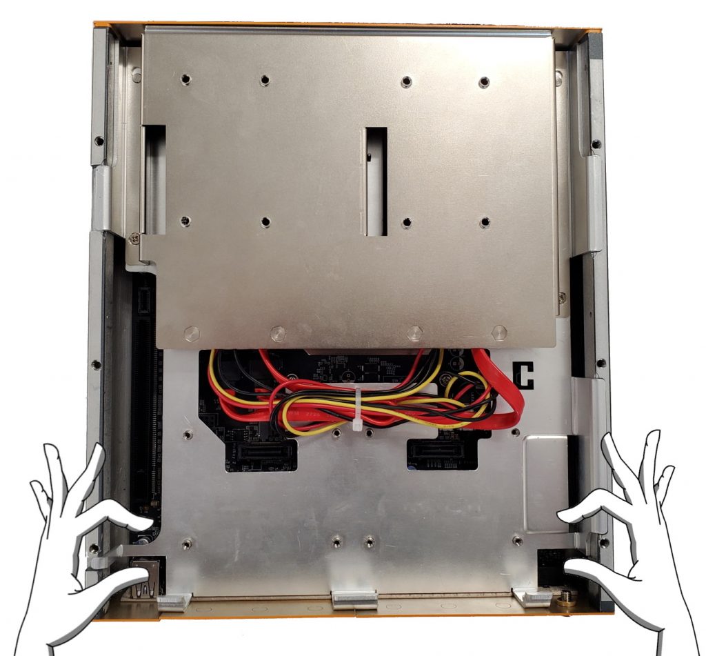
- Grab the metal plate where shown
- Lift upwards and pull towards you to remove the plate
- In case the thermal pads become displaced during disassembly, a reference guide is shown below. Note that the blue film will not be present as it is removed during initial assembly.

K803 Disassembly
Opening the system does not void the manufacturer’s warranty, however, some precautions are necessary to avoid damaging the unit. Damage caused while opening or modifying the system internals may not be covered by the warranty.
- Perform this disassembly in an area free of static discharge
- Before beginning, touch a grounded metal surface to discharge your body of static electricity
- Turn the unit upside down and remove the 6 screws from the bottom plate.
- Pry the bottom plate off

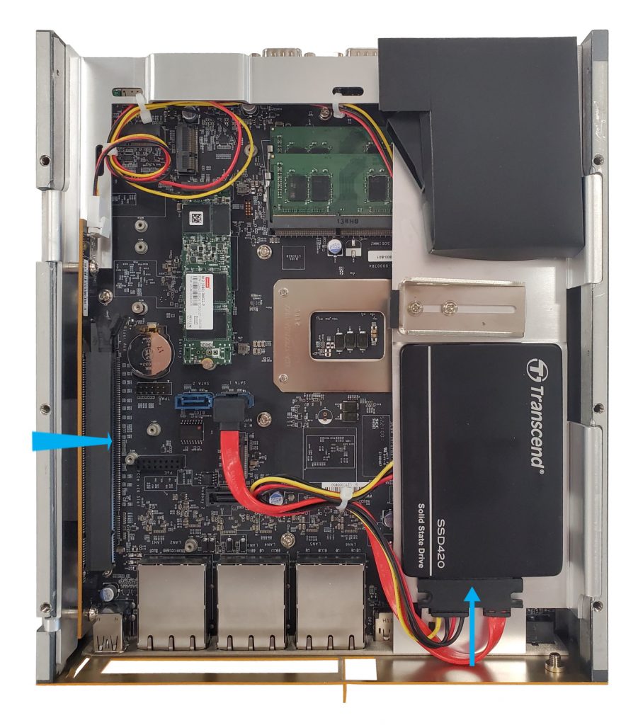
- The internals of the system can now be accessed.
- The riser card (for PCIe installation) can be difficult to install/remove. It is not recommended to remove this part, but if needed, the metal plate can be lifted upwards slightly. For example to access the RAM slots.
Any damage caused while removing/installing the mid-plate is not covered by warranty.
Installing a PCIe Card (K803)
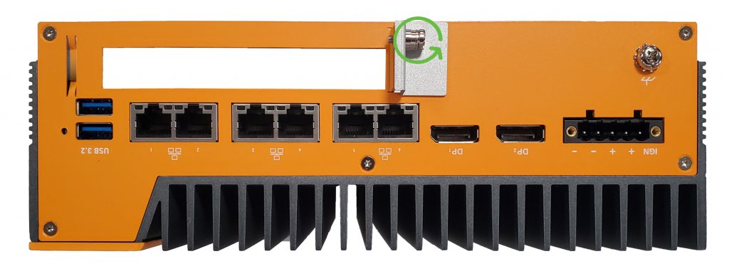
- Remove the retaining screw from the outside of the case.
- Remove the metal slot cover.
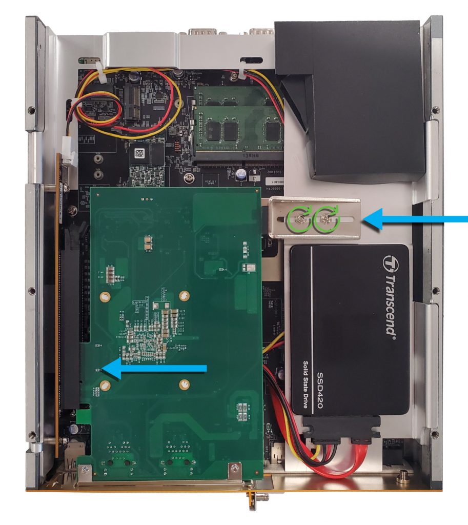
- Insert the PCIe card into the slot. Ensure it fully seats.
- Loosen the screws on the brace bracket. Move the bracket so it touches the card. This will prevent it from moving.
- Tighten the screws back down.

- Reinstall the external mounting screw.
- Card installation complete.
K804 Disassembly
Opening the system does not void the manufacturer’s warranty, however, some precautions are necessary to avoid damaging the unit. Damage caused while opening or modifying the system internals may not be covered by the warranty.
- Perform this disassembly in an area free of static discharge
- Before beginning, touch a grounded metal surface to discharge your body of static electricity
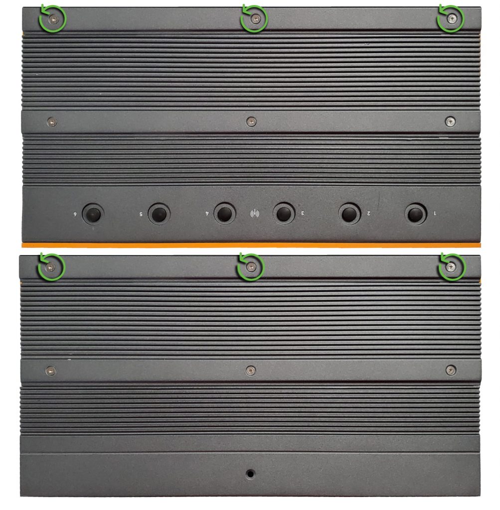
- Turn the system upside down and remove the 6 Torx T8 screws from the sides.
- Remove the bottom plate.
Installation of Parts
Installing a PCIe Card
PCIe cards can be installed to the K700-X2, K803, and K804 expansion bays. The maximum dimensions for a PCIe card depend on the platform, and are as follows:
K700-X2 Max PCIe Dimensions: Single OR Double slot height, 211 x 129 x 41mm (8.31″ x 5.08″ x 1.61″ in)
K803 Max PCIe Dimensions: Single slot height, 111mm H x 241mm L (4.4” H x 9.5″ L in)
K804 Max PCIe Dimensions: Single OR Double slot height, 111mm H x 241mm L (4.4” H x 9.5″ L in)
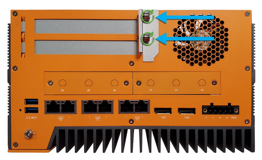
- Remove the two exterior screws from the PCIe retention bracket.
- Remove any PCIe blanks.
- If you are installing a single slot card, snap them apart and reinstall 1 PCIe blank into the upper slot.
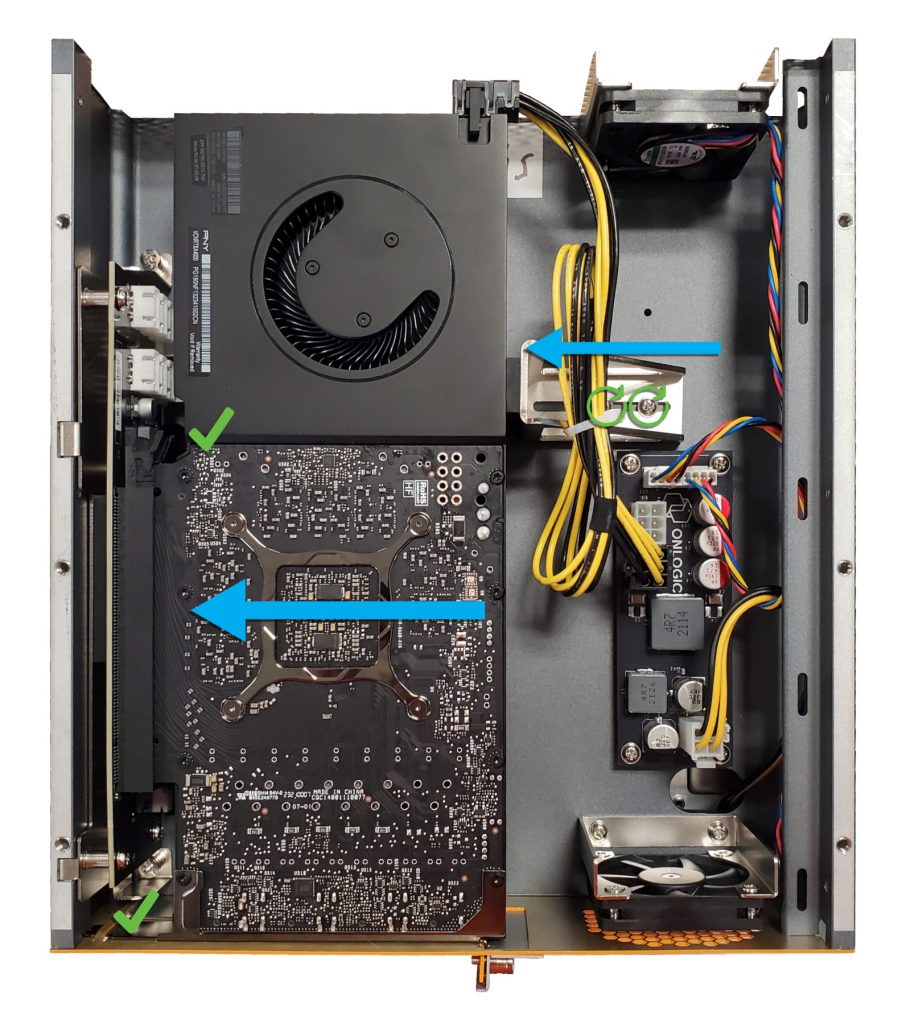
- Insert the PCIe card
- Ensure it clicks into the slot and the backplate slots into the system.
- Connect any required PCIe 6/8 pin power connectors. Cables can be found in your accessory box.
Note: PCIe power board may be optional, depending on the system’s configuration.
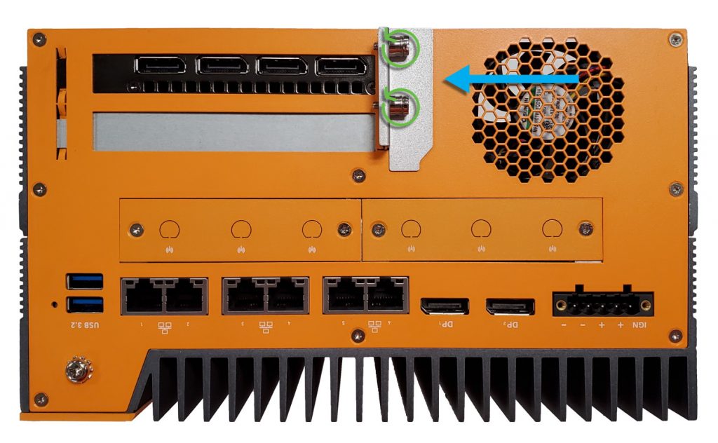
- Reinstall the retention clip and hand tighten both screws.
- Reinstall the bottom cover and the process is complete.
Installing the optional External Fan
The external fan is an optional add-on for the K700 & K800 series, which provides active cooling. This adds a 120mm case fan and moves approximately 110 CFM of airflow.
The K700 and K800 series use the same external fan. It can be installed by removing the branding plate (on the top of the system) and installing the following screws:
- x2 on the top (under the branding plate)
- x1 on the side
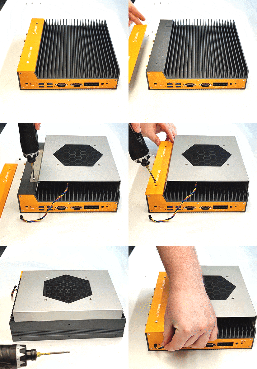
The external fan uses a magnetic dust filter. The filter should be cleaned regularly. If the filter is misplaced, our replacement part SKU is FANCPD-MESH. This can be ordered by reaching out to our sales team.
Installing M.2 Storage
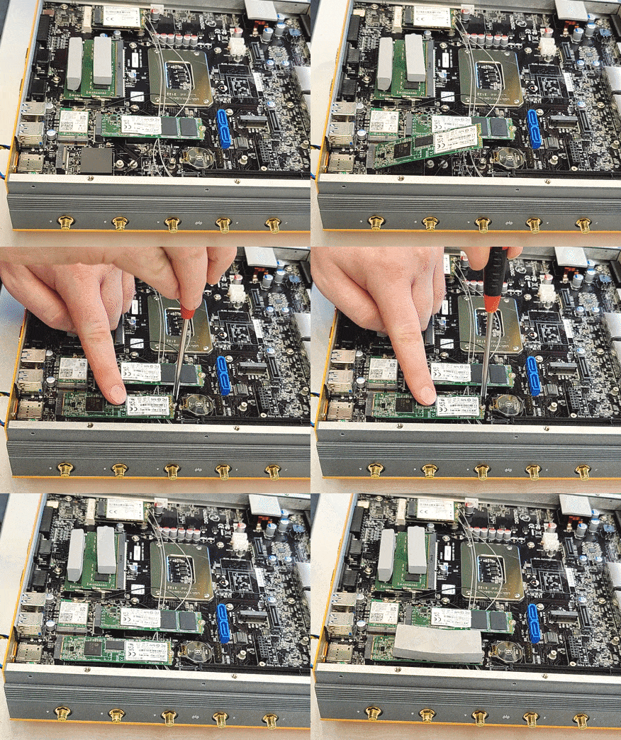
- Slide M.2 storage drive into slot
- Gently press drive down flat and secure with M.2 screw
- Apply thermal pad
Installing the PoE module
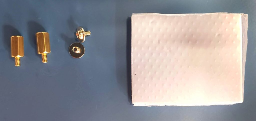
The PoE kit includes the PoE modules itself, plus needed standoffs, screws, and thermal pad for the installation.
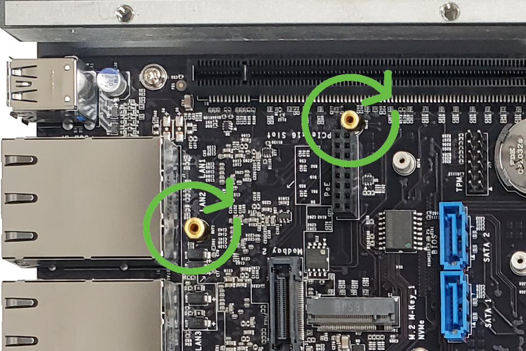
- Install the standoffs. Gently hand tighten – they are fragile.
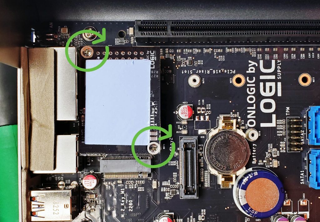
- Install PoE module onto connector. Double check that the pins align.
- Install 2x screws
- Peel and stick thermal pad
Troubleshooting
Clearing the CMOS
If the K800 fails to power on or is otherwise unresponsive, a CMOS reset may help. Follow the procedure outlined below to clear the CMOS.
- Unplug the system completely – remove power and all peripherals
- Use a long, thin tool, such as a straighten a paperclip
- Locate the unlabeled CMOS reset hole next to the HDD LED
- Using the tool/paperclip, depress the button inside for 30 seconds.
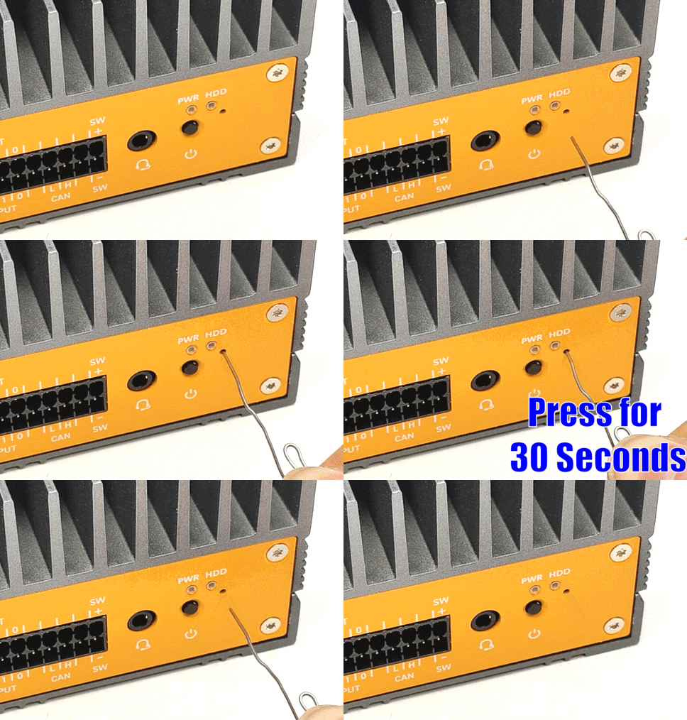
- Reconnect the system and turn it back on.
- Do not touch the system for 2 minutes. It may reboot several times while it reconfigures the CMOS.
- If successful, the unit should boot back up and run normally. It is now ready to use again. If the unit is still not responsive, reboot it one more time and then contact OnLogic Tech Support.
Can’t access the BIOS, System loads straight into the OS
The system supports Fast Boot, which is a configurable BIOS setting. With Fast Boot enabled, the unit will disable booting to Network, Optical, and USB/removable drives. Video and USB devices (such as keyboards) will not initialize until the OS loads. This can make it difficult to reinstall an OS, or change any BIOS settings, and make the BIOS harder to access. To enter the BIOS follow the steps below for your specific OS.
Windows
From the Start Menu, hold Shift and click Restart to access the Recovery screen, then go to “Advanced” and select “UEFI Firmware Settings”. The system will reboot and allow access in the the BIOS. You may need to repeatedly press DEL/F2 keys while the system is rebooting.
Linux
From Terminal, run the following command:systemctl reboot --firmware-setup
This will trigger the system to reboot and allow access into the the BIOS. You may need to repeatedly press DEL/F2 keys while the system is rebooting.
Once you’ve accessed the BIOS, you can find the Fast Boot setting under the Boot tab.
10Gb Ethernet Modbay disappears from OS
K800 series systems outfitted with the 10Gb Modbay (MODBAY-10GLAN01) may experience issues while in use, causing the ports to crash and become unusable. To fix this issue, download this file and follow the Update Instructions.
Note that the system must be booted into a Windows environment for this Update. A temporary Windows installation can be used on the system, or the unit(s) can be returned to OnLogic. Contact OnLogic Tech Support for RMA details.
Orders shipped after 11/20/2023 already have this update applied
10Gb Ethernet Modbay limited speed
If you have a 10 Gb Modbay installed in your system, and it is not operating at full speed, you may need to update the ethernet controller firmware. It should be at least version 3.6 or higher.
There are different update steps depending on if you’re running Windows or Linux. Download the relevant steps and follow the steps in the downloaded file:
CAN bus connection instability
If you experience issues with using or accessing the CAN bus on your K800 system, this can be resolved by updating to the latest microcontroller firmware. Download the firmware at the top of this page, and follow this guide:
Accessing the Microcontroller (MCU)
The embedded microcontroller unit (MCU) is used to interface and control various aspects of the system such as CAN, DIO, and ignition sensing. To communicate with the MCU, follow the steps below for your installed OS.
Windows
- Download the PuTTy tool from putty.org
- Look in Device Manager and find the highest numbered USB serial device, COM5 in this example
- Open Putty. Set the connection type to Serial and change COM1 to the COM # you found in the previous step. This example uses COM5.
- Click “Open”. This will open a virtual connection to the MCU (no physical cable is required)
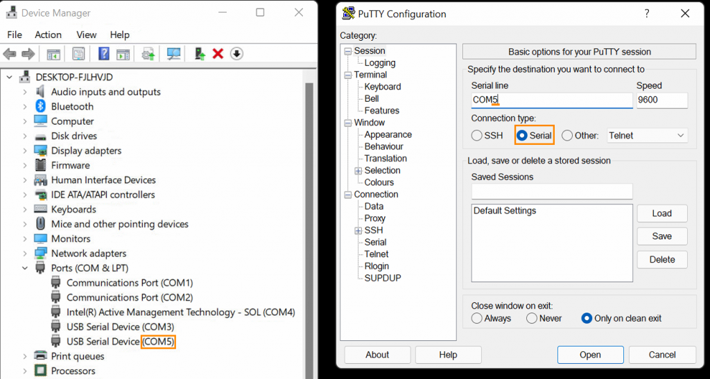
- To confirm you have the correct port open, type “help” and press enter. The help text should appear. If it does not, try a different COM port.

Linux
- Use a program such as PuTTy to interface with the microcontroller (MCU). You can run the following command to install it (you will need an active internet connection for this):
sudo install putty - The MCU will typically enumerate as
ttyACM0. It enumerates as a serial-interfaceable USB device. If you run into issues accessingttyACM0, you can run the following command to identify the other port(s):sudo dmesg | grep tty

- In this example, the MCU is on
ttyACM0. Open PuTTy, enter the port #, and set the connection type as “Serial”. The other settings can be left on their defaults (i.e. baudrate = 9600).

- To confirm you have the correct port open, type “help” and press enter. The help text should appear. If it does not, try a different port #.

Microcontroller Commands
A full list of microcontroller commands be be found here in the User MCU Shell documentation here:
Automotive Timings
Feature Overview
The ignition sense feature can be used to turn the Karbon unit on and off with a battery, or vehicle’s ignition. It can also be used in non-automotive applications using a switch instead.
An example configuration is shown below. The switch connects positive DC power to the IGN pin. The unit will turn on when power is applied to the IGN pin, and turn off when power is removed. These events have configurable delays.
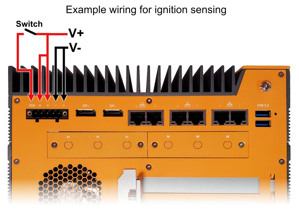
Enabling and controlling ignition sense
Ignition sensing can be enabled and adjusted through a virtual COM connection to the system’s microcontroller (MCU). You can open this communication to the MCU using a program such as PuTTy. Refer to the steps above, Accessing the Microcontroller (MCU), for help accessing the MCU.
Ignition sensing simulates a power button press. In Windows, the default behavior of the power button press is to put the system into Sleep mode. You will want to change that to “Shut Down” instead.

Example ignition settings
The following shows an example configuration for automotive timings. Enter each command one by one.
For further help text, type lpmcu config
| Command | Effect |
|---|---|
lpmcu config automotive-mode true | Enables automotive mode |
Command:lpmcu config startup-timer [X]Example: lpmcu config startup-timer 10 | Effect: turn on X seconds after IGN pin receives power Example: turn on 10 seconds after IGN pin receives power |
Command:lpmcu config hard-off-timer [X]Example: lpmcu config hard-off-timer 60 | Effect: force shutdown system after X seconds (failsafe to protect battery) Example: force shutdown system after 60 seconds (failsafe to protect battery) |
Command:lpmcu config soft-off-timer [X]Example: lpmcu config soft-off-timer 20 | Effect: shutdown X seconds after IGN pin loses power Example: shutdown 20 seconds after IGN pin loses power |
CAN & DIO
The Karbon 800 has an embedded NXP i.MX RT1050-series microcontroller that can communicate with the host processor over USB. Its features include:
- Configuring the system LEDs
- Reading/writing the system DIO
- Using system Digital Outputs in PWM mode
- Configuring system automotive settings
- Managing the system CAN interface
To provide access to these features, the MCU supports a composite USB-CDC VCOM connection (VID: 0x353F, PID: 0xA101):
- Interface 0: A UART terminal supporting commands for a range of features
- Interface 2: A dedicate USB serial CAN interface
C:\Users>python -m serial.tools.list_ports -v

COM15
    desc: USB Serial Device (COM15)
    hwid: USB VID:PID=353F:A101 SER=500100D20F3861D2 LOCATION=1-11:x.2 <--- CAN Port
COM16
    desc: USB Serial Device (COM16)
    hwid: USB VID:PID=353F:A101 SER=500100D20F3861D2 LOCATION=1-11:x.0 <--- UART Port
The MCU shell is a fully-featured virtual UART shell exposed over the MCU’s first USB CDC-ACM interface. This shell supports both command history and line editing, and can optionally serve as an output target for driver log messages. For a complete command reference see, the shell command reference.
Entering the ROM Bootloader (manual):
1. Detach the K800 system from wall power
2. Use a paper clip to depress the settings switch located above the front USB 3.0 ports
3. With the switch held down, re-attach system power
4. The MCU should now boot into the NXP ROM bootloader
Entering the USB Bootloader (manual):
1. Boot the K800 to the operating system
2. Use a paper clip to depress the settings switch located above the front USB 3.0 ports
3. With the switch held down, send the ‘reset’ command to the MCU’s UART port
4. The MCU should now boot into the second stage USB bootloader
DIO/CAN/Power Switch header
The Karbon 800 series 20-Pin header provides the following interfaces: 8-bit (4-in, 4-out) Digital Input Output (DIO) or General Purpose Input Output (GPIO) with optically isolated terminals, one CAN bus connection, and an optional external power switch connection.
The DIO is optically isolated, meaning that the terminal is separated from other motherboard features for protection. The DIO terminal requires external power from a 5~48V DC source through Pin 20 with GND to Pin 19 in order to function.
The Isolated Power Supply (ISO PSU) can be a voltage source from 5~48V to interface with external digital IO. The maximum power draw from the supply should not exceed 0.6A under normal operating conditions. Individual DOut pins will be damaged by loads in excess of 150mA. The ISO PSU must be a DC Limited Power Source (LPS) power supply.
Mating power switch cables should be a twisted-pair wire with floating shield to assure proper
immunity to EMI/RFI. It is recommended to keep wires at less than 3 meters in length. Any remote power switch connected between pins 1 and 2 should be momentary contact type only.

Connection Diagrams


DIO & LEDs
Examples:
All digital inputs/outputs support reading the current logical state of the pin. Digital outputs additionally support setting the output state of the pin, and digital inputs support reporting the transition count of the pin (both edges). The K800 also support configuring digital outputs as PWMs, and configuring the PWM output’s pulse and duty cycle. For a additional command reference see, the shell command reference. The DIO can also be changed to Byte Mode as documented below.
# Turn on LED 0 output
uart:~$ dio set LED0 0 true
# Check the state of Digital Input 0
uart:~$: dio get DIO0 input 0
While the microcontroller shell is intended for human interaction, it can be used to programmatically control the MCU. To avoid a number of pitfalls when doing so, observe the following best practices:
- On Linux, use the symlinked device nodes inside
/dev/serial/by-idinstead of hardcoding/dev/ttyACMxdevice names./dev/ttyACMxnumbering is - unstable;
/dev/serial/by-id/usb-OnLogic_<device>-if00will reliably point to the terminal interface. - When writing Linux shell scripts, ensure that the echo flag is disabled on the TTY by running
stty -F /dev/serial/by-id/<device> -echobefore - interacting with the shell. Most serial libraries (pyserial, serialport-rs, etc.) will automatically disable this flag.
- When sending a command, precede it with a ‘\x03’ byte to clear the terminal’s line buffer and ensure that the command is interpreted correctly. Follow the command with a ‘\r’ or ‘\n’ character to execute the command.
- Send less than 64 bytes at a time. To send longer commands, explicitly flush the port’s output buffer in between each block of 64 bytes.
Byte Mode
When using byte mode, DIO commands are sent in the form of command packets, and each command will receive a status (and optional data) as a response.
The command header is eight bytes in length:
| Bytes | Description | Options |
| 0 | The message ‘start of frame’ byte. | Must be 0x01, or the message will be rejected. For non request/response frames, it is instead set as 0x02 |
| 1 | Indicates the kind of command transmitted | Must be one of the Valid Command Kinds |
| 2 – 3 | The status of the last command | Should be zero when sending a command, one of Status Codes when receiving |
| 4 | The length of the transfered command data | Must be less than 56, and equal to the length of the command body in bytes |
| 5-7 | Reserved | Must be 0x00 |
All command headers must indicate the type of data to follow, by setting the command kind:
| Kind | Value (u8) | Size | Description |
| DIO | 0x00 | 8 bytes | Commands that get and set the state of MCU controlled digital IO banks |
| CAN | 0x01 | 6 bytes | Sideband configuration and reporting for CAN devices |
| Reset | 0x02 | 0 bytes | Causes a cold-reset of the microcontroller |
| Version | 0x03 | 8 bytes | Reports the firmware version of the running application image |
| Ignition | 0x04 | 10 bytes | Configures automotive and power features on supported devices |
| Disable | 0x05 | 0 bytes | Disables byte processing of incoming data, and returns to an interactive shell |
Each command sent will recieve a response from the microcontroller. This response may contain data, but can always be examined to determine if the command succeeded.
| Code | Value | Description |
| Success | 0x0000 | The last command was processed successfully |
| Invalid Device | 0x0001 | The device indicated by the command exceeded the number of devices available to the system |
| Unbound Device | 0x0002 | The device targetted exists, but the MCU was unable to attach to and communicate with it |
| DIO – Invalid Pin | 0x0003 | The target pin exceeded the number of inputs or outputs actually present |
| DIO – Pin Read Failed | 0x0004 | Reading the state of the targetted pin failed for an unknown reason |
| DIO – Pin Write Faield | 0x0005 | Writing the state of the targetted pin failed for an unknown reason |
| DIO – Set Mode Unsupported | 0x0006 | Setting the DIO mode to push-pull or sink-source is not supported |
| Invalid Command | 0x0007 | The subcommand requested was outside of the valid range for the message kind |
| Bad Message Kind | 0x0008 | The message kind was not one of Valid Command Kinds |
| Version – Read Failed | 0x0009 | Reading the application version failed for an unknown reason |
The DIO command format is as follows:
| Bytes | Description | Options |
| 0 | The DIO action to perform on the device | Must be one of DIO Actions |
| 1 | The bank of digital IO to target, or the number of devices | Must be between 0 and the number of DIO banks available on the platform |
| 2 | The pin index to get or set | The output pin index starts at 0, the input index starts at 0 + n-outputs |
| 3 | The current state of the pin (if read), or the state to set (if written), or the mode to set (mode 0=sourcing, mode 1=sinking) | 0 or 1 |
| 4 – 7 | The edge-count of the pin, or the number of inputs/outputs | 0 – MAX_UNSIGNED_INT (u32) |
The digital IO command supports the following actions:
| Action | Value (u8) | Description |
| Get | 0x00 | Read the state and count of an input, or just the state of an output |
| Set | 0x01 | Set the logical state of a digital output |
| Set Count | 0x02 | Set the edge count of a digital input to the passed value |
| Set Mode | 0x03 | Switch between sink-source and open-collector drive mode on supported hardware |
| Num Devices | 0x04 | Reports the number of DIO banks available on the device |
| Num Outputs | 0x05 | Reports the number of outputs available to the indicated device |
| Num Inputs | 0x06 | Reports the number of inputs available to the indicated device |
CAN
The Karbon 800 has an on-board CAN (Controller Area Network) 2.0 A/B interface. In general, the CAN bus consists of two main signal lines, CAN High and CAN Low. CAN High is biased at a high voltage potential of ~3.5 Volts and CAN Low is biased at a low voltage potential of ~1.5 Volts. The nominal voltage measured between the two signal lines is ~2.5 Volts, serving as a reliable indicator of the K800 CAN bus operational status. Additionally, the CAN bus operates in two states: dominant and recessive. Dominance is represented by logic level 0 and recessive is represented by logic level 1. The K800 CAN interface supports configurable bitrates from 100k – 1M and two message parsing modes: slcan and std.
slcan: an abbreviation for serial line can, is a virtualizing protocol used to transmit CAN messages over serial communication. This bridges the gap between the operating system and the unique differential signaling utilized in the CAN protocol. slcan makes the CAN bus appear as a network interface on the operating system, and can be even be identified as such when looking through the kernel buffer on Ubuntu via
sudo dmesgSpecifically, the K800 supports the following bitrates using slcan interface:
10 20 50 100 125 250 500 800 1000 Kbits/s
std: CAN bus send and receive messages are communicated in their native CAN format. This allows for direct low-level communication between the in-system K800 microcontroller and CAN-compatible devices. The std method of operating the CAN bus can be used without the need for intermediate serialization to communicate with an operating system.
Further details about the CAN bus can be found in the provided resources:
- https://en.wikipedia.org/wiki/CAN_bus#Frames
- https://community.nxp.com/t5/NXP-Tech-Blog/101-Controller-Area-Network-CAN-standard/ba-p/1217054
Configuring the K80X as a CAN device
This section describes the physical connection and software configuration needed to set up the K80X platform as a CAN controller in either the Microsoft Windows or Ubuntu Linux based operating systems. Example programs are written in both Python (for both Windows and Linux) and Bash (for Linux).
Materials Required:
- Hookup or twisted pair wires
- 120 Ohm termination resistors (depending on the CAN setup)
- CAN member devices compliant with CAN 2.0 A/B. In our example we will use a second K80X to act as the endpoint device.
Example Network Implementation:
Diagram of a simplified CAN bus network. The figure above shows: 1) Two termination resistors at each end of the bus, 2) required endpoints of the bus acting as either transmitters or receivers, 3) High and Low CAN bus lines, and 4) additional (optional) network members connected on the same signal lines.
Operation Instructions:
The use of the K800 CAN bus can be achieved in four steps.
Step 1: Locate CAN High and CAN Low terminals on the 20-Pin header next to the system power button.
Step 2: Connect CAN Low, CAN High, and (commonly used) ground wires to their designated locations using the Dinkle 0159-0320 20 pin connector. Additionally, bridge CAN Low and CAN High terminals with the proper termination resistor (120 Ohm in this example).
Step 3: Configure the second K80X system with the same wiring connecting the CAN High and Can Low signals of each system. Ensure a second 120 Ohm resistor is used as close as possible to the second K80X 20 Pin connector.
Step 4: Activate the software interface to operate the CAN bus.
The GitHub repository here:
https://github.com/onlogic/K800-CAN-supplemental-material
Provides two utilities with instructions on controlling CAN bus parameters and sending/receiving CAN data in the code comments. Both the software utilities use slcan as the interface to communicate with the CAN bus. The installation commands for required dependencies are included in the header comments of each respective code file.
Python3 CAN Utility [Ubuntu and Windows Compatible] : https://github.com/onlogic/K800-CAN-supplemental-material/blob/main/k800_can_utility.py
Usage on Windows:
python k800_can_utility.py [-h] [-m {s,r}] [-b {10,20,50,100,125,250,500,750,1000}] [-l {off,on}]Usage on Linux:
sudo python3 k800_can_utility.py [-h] [-m {s,r}] [-b {10,20,50,100,125,250,500,750,1000}] [-l {off,on}]NOTE: Run the Python CAN utility with sudo privileges on Ubuntu.
Output of —help flag for the Python command line argument:
python k800_can_utility.py --help

usage: k800_can_utility.py [-h] [-m {s,r}] [-b {10,20,50,100,125,250,500,750,1000}] [-l {off,on}]

K800 CAN Bus Utility

options:
  -h, --help            show this help message and exit

  -m {s,r}, --mode {s,r
                        send (s) or receive (r): send generated data or continually receive

  -b {10,20,50,100,125,250,500,750,1000}, --bitrate {10,20,50,100,125,250,500,750,1000}
                        CAN bus baudrate in kbps (ranges allowed by slcan: [10, 20, 50, 100, 125, 250, 500, 750, 1000]
  -l {off,on}, --leds {off,on}

Incorporate LED check functionality in program
Examples in:
Windows:
python k800_can_utility.py -m s -b 500 -l on

python k800_can_utility.py -m r
Linux:
sudo python3 k800_can_utility.py -m r -b 1000 -l off

sudo python3 k800_can_utility.py -m s
Bash Script Utility [Ubuntu Compatible Only] :
https://github.com/onlogic/K800-CAN-supplemental-material/blob/main/k800_can_utility.sh
1. First, set permissions to be executable by user who owns the file:
chmod u+x k800_can_utility.sh2. Then run the executable using:
./k800_can_utility.sh {s|r} <bit_rate> <led>Examples:
./k800_can_utility.sh s 100 off
./k800_can_utility.sh r 20 on
./k800_can_utility.sh r  # Uses default bit_rate and no LED check
Two channels, a blue channel representing CAN High and orange representing CAN Low. Both CAN High and CAN Low will default to a 2.5 nominal voltage in the absence of a signal. This is useful for debugging if there is uncertainty whether the signal is properly broadcasting.
[Optional] If the LED flags are active in either the Python script or the Bash script, the onboard LEDs on the K800 will turn on and off before and after each CAN session, respectively.
Sample Program Outputs:

Initializing output from: sudo python3 k800_can_utility.py -m r -b 100 -l on. This indicates the proper eMCU Port location, Hardware ID, and Device.
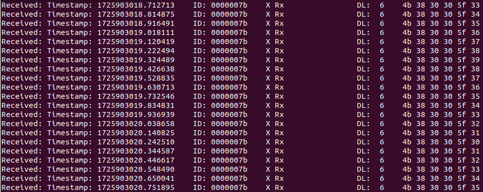
Terminal output of ‘receive mode’ using the Python utility through the command:
sudo python3 k800_can_utility.py -m r -b 100 -l on
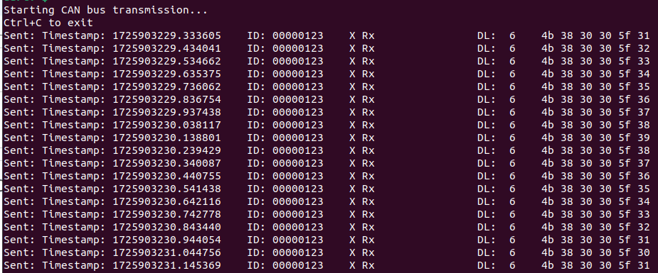
Terminal output of ‘send mode’ using the Python utility through the command:
sudo python3 k800_can_utility.py -m s -b 100 -l on
M12 LAN Expansion (optional, must be factory installed)
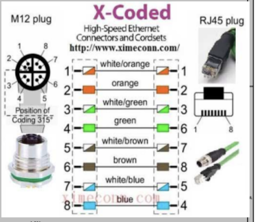
The 3x M12 LAN Expansion (MODBAY-M12LAN01) adds additional M12 X-coded GbE LAN ports to the K802 and K804. This ModBay uses dedicated Intel I210-IT network controllers for each port which support speeds up to 1 Gbps.
Supported cables:
● CABLE-M12-RJ45-5M (5 Meter X-coded M12 to RJ45)
● CABLE-M12-RJ45-10M (10 Meter X-coded M12 to RJ45)
Operating Temperature: -40~70°C
