
The DA-1000 can be opened by the user. This does not void the warranty, however, any damage caused by doing so will not be covered.
The following steps will walk you through opening your DA-1000 case, as well as auto-powering on and clearing CMOS.
Replacement Power Connector
If you need an additional mating connector for your system’s power port, you can acquire our CBP123 component from our website, here.
How to Enable Auto Power On
The DA-1000 has two options for auto power on. In this section we will go over the two options step by step.
Option 1: Hardware
The easiest of the two methods to auto power on the DA-1000 is to use the switch on the front side of the unit. Slide the switch to AT mode to enable auto power on.

The downside of this method is that the power button is completely disabled. If you shut down the PC, you will need to cycle power to restart it. If that is an issue for your use case, use option 2 instead.
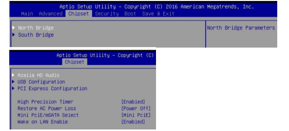
Option 2: BIOS
- Power on the system and immediately press the Del key a few times to access the BIOS.
- Navigate over to the Chipset tab and open the South Bridge menu.
- Change the option REstore AC Power Loss to [Power on]
- Navigate to the Save & Exit tab and choose “Save Changes and Reset”
Opening the DA-1000 Case and Clearing CMOS
Disassembling the DA-1000
- Remove the 4 Torx screws from the bottom of the system.
- The bottom plate will then be loose and can be removed.

- If the system contains a 2.5″ storage drive it will need to be removed. Remove the 3 phillips screws and slide the drive bracket outward as indicated by the arrow.

Clearing the CMOS
- The CMOS Battery and CMOS Reset switch are now exposed. The CMOS can be cleared by moving the blue switch to the ON position for 30 seconds.
- If you are only looking to clear the CMOS, STOP HERE and re-assemble the unit.
- To continue with the disassembly, remove the mSATA drive (if installed)

- Remove the 5 screws circled in red.

If the unit has WiFi, special steps are needed as the antenna pigtail covers one of the mainboard screws. It is possible to remove the screw by
carefully using a small Phillips driver at a slight angle. The pigtail can also be easily removed by loosening the nut on the outside.
- The chassis will now slide apart as pictured.
- Pick up the system with two hands and pill it apart. Moderate force may be needed to break the thermal seal.

- The underside of the system is now accessible and the RAM can be replaced.
- During reassembly, be cautious of the WiFi pigtail routing. Ensure it is away from the screw holes so you do not put a screw through it.

Additional Manuals and Drivers for DA-1000
DA-1000 Motherboard Manual
https://drive.google.com/file/d/143yaTWaEgdLKHRNX_Ls5pg8Z6NBFrvuy/view
Over/Under Voltage Info
https://drive.google.com/file/d/1FLMFYW_YvJz0GBqLGyABODTwkM-207ze/view
Drivers for DA-1000
https://drive.google.com/drive/folders/1tGIiGC4sM0pl1z7osareLuqHR0T5iHFL
How to install the SIDE02 DIN mount
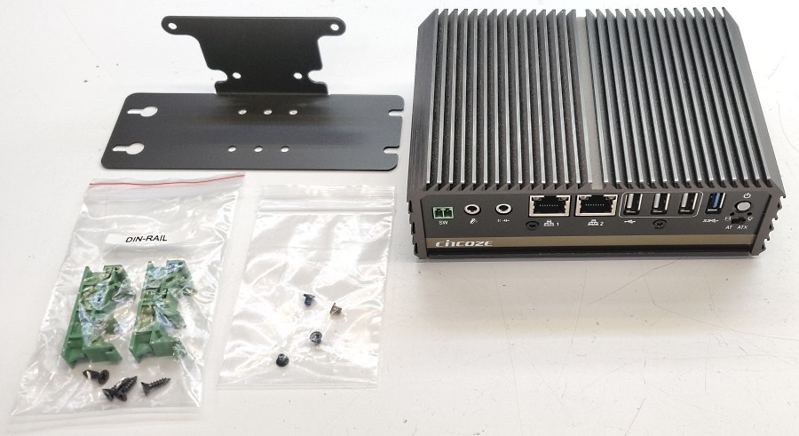
- Remove the mounting hardware from the box
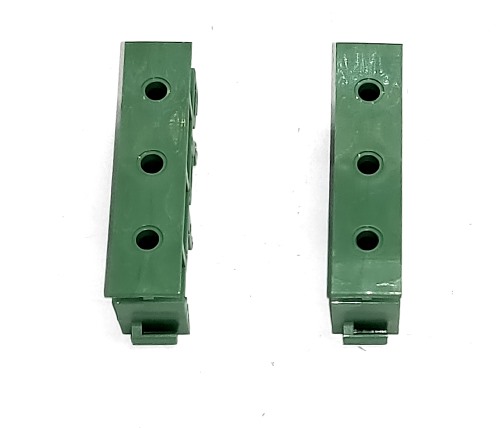
- Set the green DIN clips on your worksurface, ensuring the plastic tabs are facing the same way.
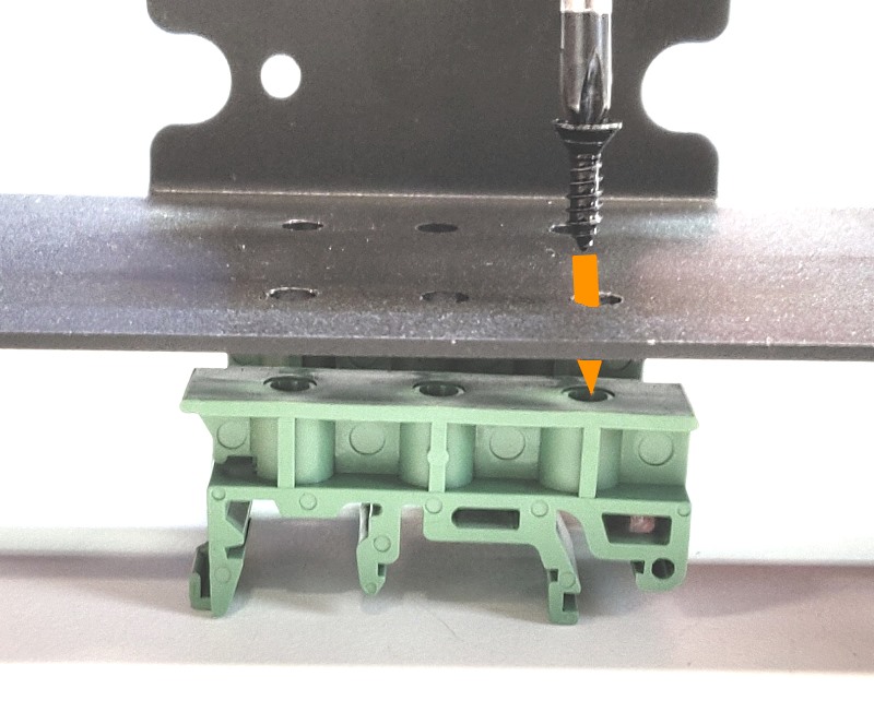
- Using the screws that came in the bag with the DIN clips, install them onto the mounting bracket.
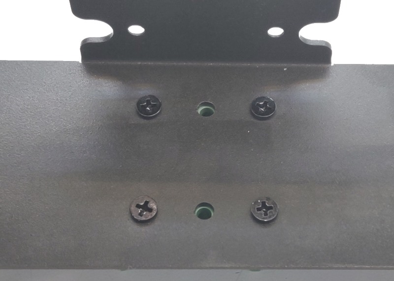
- Install 4 screws total, leaving the middle hole open
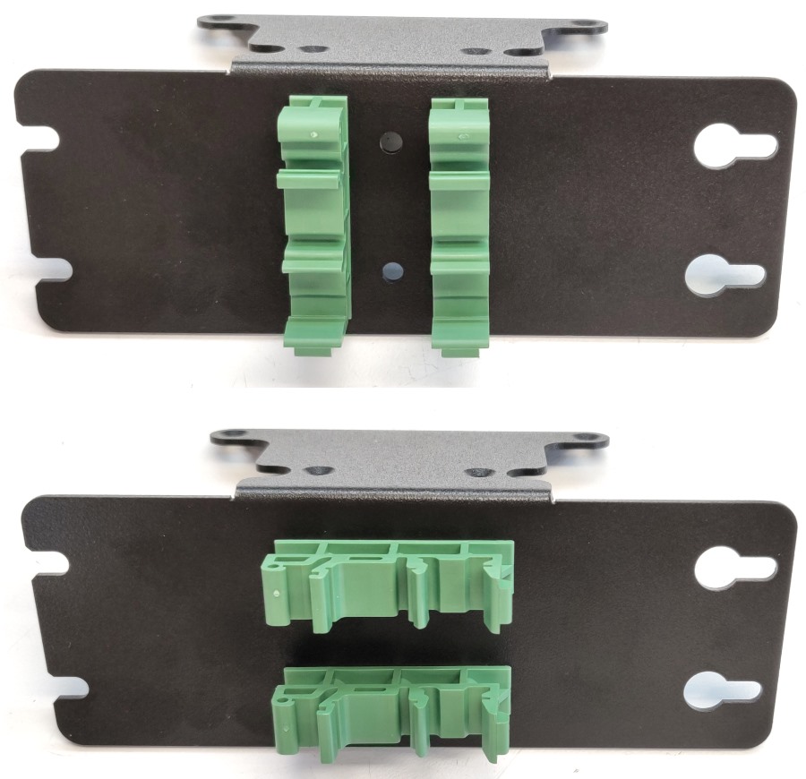
- Either orientation is acceptable, it can be rotated depending on your installation needs.
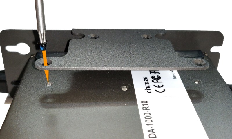
- Mount the bracket to the bottom of the system using the 4 included M3 Torx T10 screws
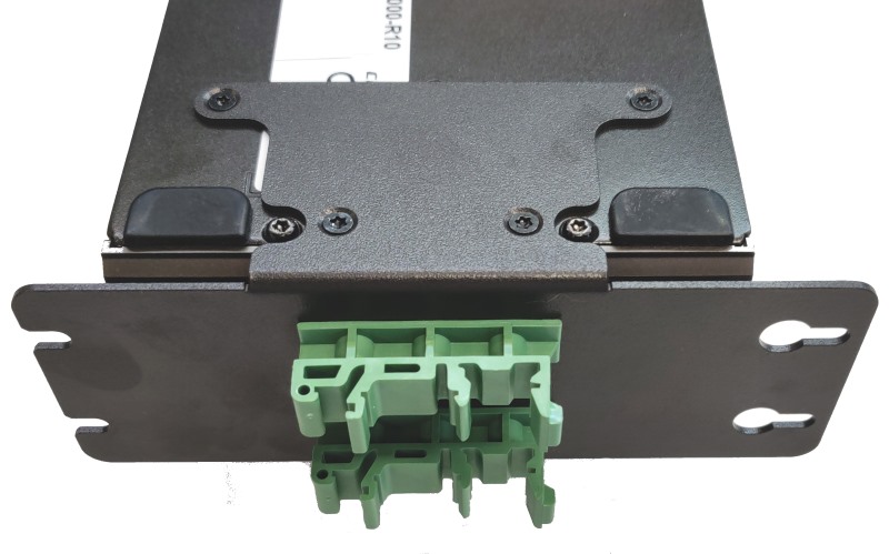
- The bracket is now installed and ready for use.