Documents and Downloads
Spec Sheet & Dimensional Drawings
Drivers
Pykarbon MCU Programming Guide
BIOS Updates
| Bios Version | Link |
|---|---|
| D8000A11 | Download |
Frequently Asked Questions (FAQ)
The K300 contains a microcontroller which among other things, controls the timings. You can read more on the controller here: https://support.onlogic.com/onlogic-systems/rugged/karbon-series/karbon-series-using-the-serial-interface
Check out our Update Guide here:
https://support.onlogic.com/onlogic-systems/rugged/karbon-series/firmware-update/
802.3at – up to 25.5 watts per port.
PD Voltage: 42.5 V – 57.0 V
Maximum Amperage: 600 mA
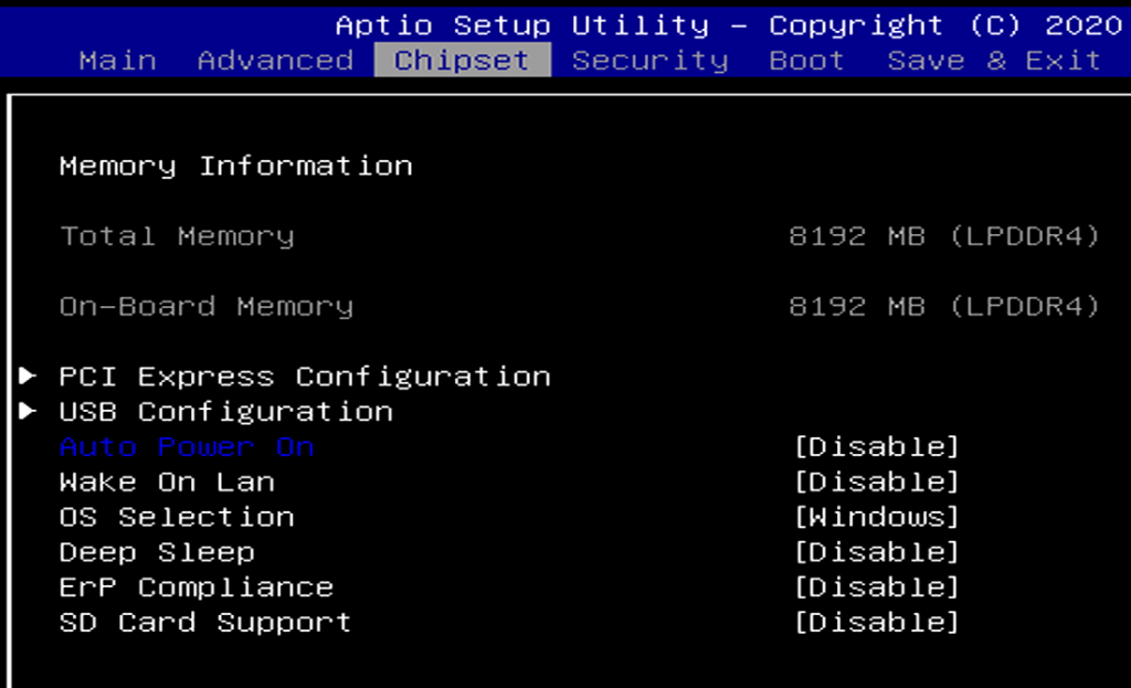
Repeatedly press Del to enter the BIOS and go to Chipset > Auto Power-On
The microcontroller and CAN ports are addressed via /dev/ttyACM0 and /dev/ttyACM1. The physical COM ports are /dev/ttyS0 and /dev/ttyS1.
Enabling Auto Power On
Press Del to enter the BIOS and go to Chipset > Auto Power-On
Disassembly
Opening the K300 will not void your warranty, but you must take adequate ESD precautions to avoid damage caused by static electricity. A grounding strap is recommended.
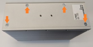
- Begin by removing the 4x Torx T10 screws from the case

- Slide and flip the bottom cover off as shown.
Component Installation
- Refer to the following motherboard schematic for component installation
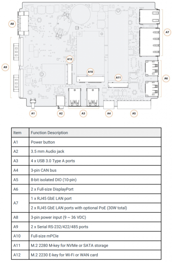
- Apply thermal pads from the accessory kit to any hardware installed

- Hinge the bottom cover back on
- Reinstall the case screws
Troubleshooting
Resetting the microcontroller
The onboard microcontroller (MCU) can be reset to resolve some boot issues, and to restore the MCU.
- Unplug the K300 from DC power
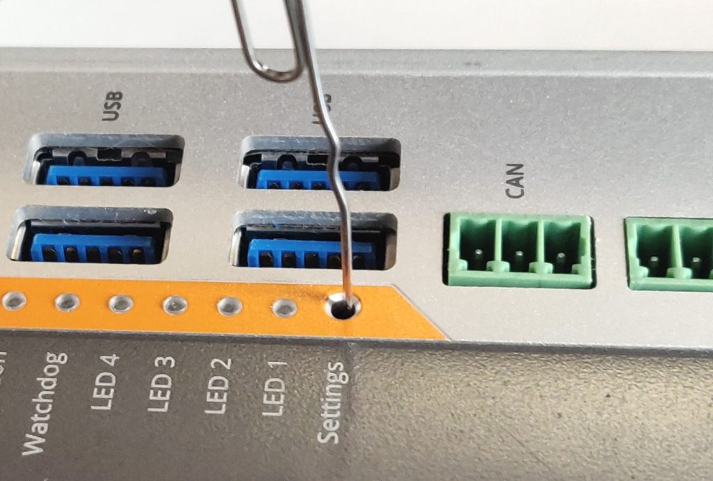
- Using a paperclip or similar object, depress the small button inside the Settings hole
- Continue to hold the button down and plug in and power on the K300
- The Watchdog LED will flash rapidly. The MCU has now been reset.
- The watchdog LED will return to normal after the next reboot.
If the MCU reset does not restore the K300 to working order, the next step is to disassemble the unit and clear the CMOS. Instructions for doing so can be found in the next section.
Clear the CMOS
If the system fails to power on or otherwise function, clearing the CMOS may help restore it to a working state.
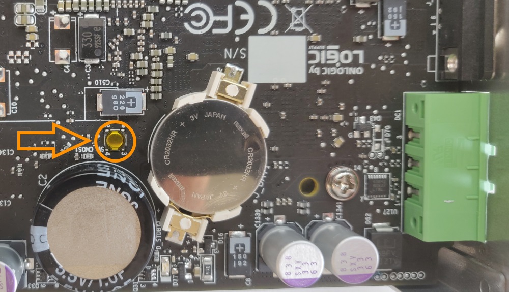
- Unplug the unit from power and follow the disassembly steps above
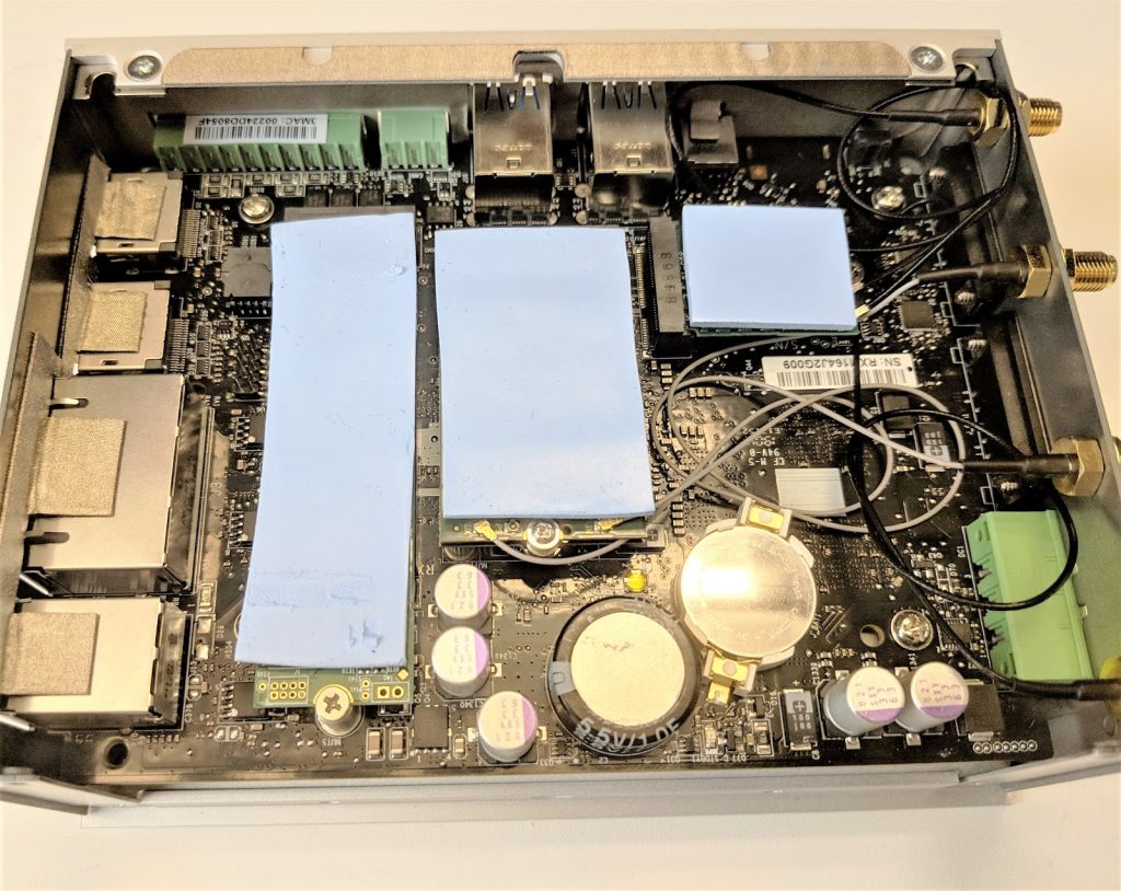
- Locate the clear button next to the battery and supercapacitor
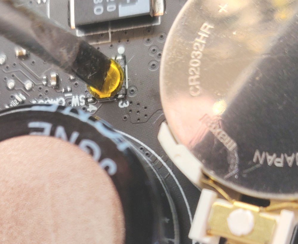
- Depress the button with a flathead screwdriver, fingernail, or similar object for 30 seconds
- The CMOS is now clear. Power the unit back on. It may reboot multiple times before resuming normal operation.
- If you continue to see issues, contact technical support.
Issues using the Microcontroller
If you’re seeing issues using the system’s microcontroller (MCU), make sure you’re running the latest firmware version. You can check your current version by opening a connection to the MCU and running the Version
If the MCU in inaccessible, or needs to be updated, you can update the MCU firmware by following our Update guide:
No audio in Linux workaround
As of this writing (4/14/2021), there is a known issue in Ubuntu 18.04 and 20.04 that causes DisplayPort audio not to work. As a workaround, one of the audio kernel modules needs to be blacklisted.
To do so, open a terminal and run the following commands:
echo "options snd-hda-intel dmic_detect=0" | sudo tee -a /etc/modprobe.d/alsa-base.confecho "blacklist snd_soc_skl" | sudo tee -a /etc/modprobe.d/blacklist.confReboot the system, and DP audio should once again be functional.
Further details can be found on this page.
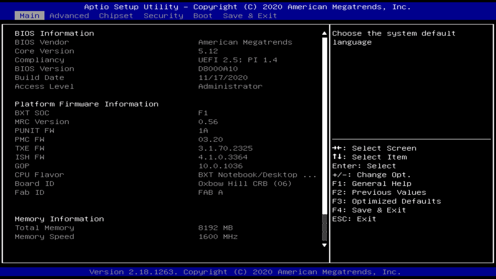
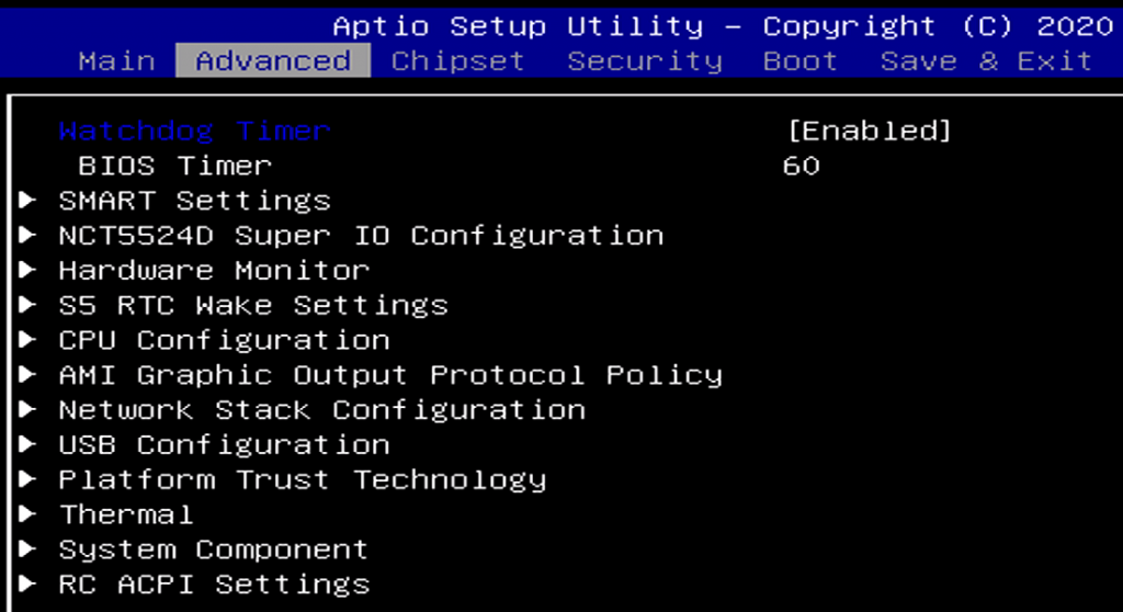
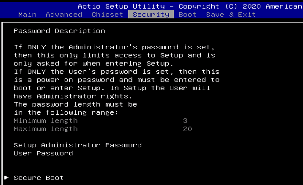
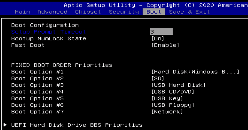
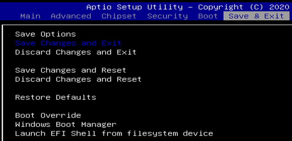
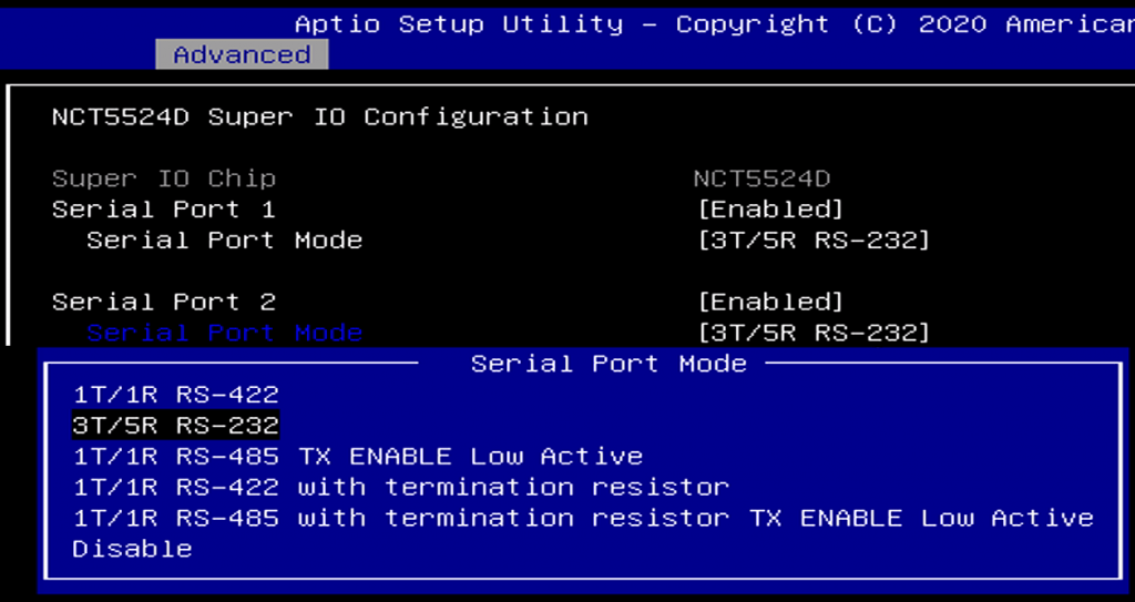
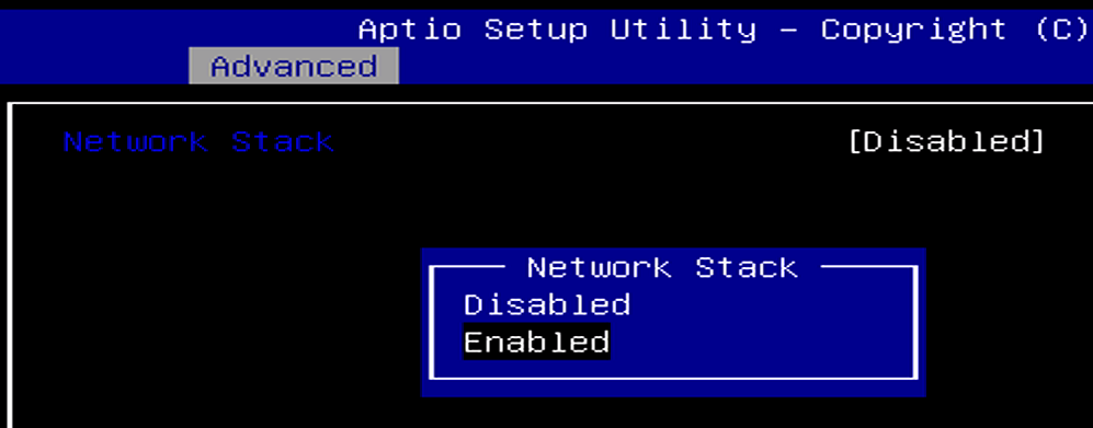
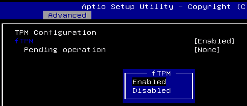
BIOS Images
System Features
CAN Bus
CANbus FAQs
The CAN bus on the K300 and K700 series computers can be modified to fit your applications. Here are some of the frequently asked questions regarding the CAN bus feature.
Messages may be sent by writing to the CAN virtual serial port, like this:
std 123 4 11223344 data
The syntax is: [std | ext] [id] [length] [data] [data | remote]
The Karbon series computers additionally support doing some of the legwork for you, and support using a terminal command to interpret and send a packet:can-message 123 11223344
The syntax is: can-message [id] [data]
So just to be clear, you use the first syntax on the CAN serial port, and the second syntax on the serial terminal.
CAN messages are delivered to the CAN virtual serial port. If you are monitoring this port in with a serial terminal, you will see the data printed out in the terminal.
Yes! This is a configuration setting, so you’ll need to access the serial terminal. From there, you have two available commands. The first is:can-autobaud
This command will attempt to detect the baud rate and propagation delay of your CAN bus. It does this by sending messages with ID 7FF, and watching for acknowledgement — so it may not work in every setting. Which is when you want to use the second command:set can-baudrate 800
The syntax is:set can-baudrate [rate](rate is in thousands)
In both cases, you can check if the baud rate was set correctly using config. Don’t forget to save your settings with save-config to ensure that it will persist after a power loss.
If things have stopped working quite right, you can reset the Karbon’s microcontroller and CAN controller by performing a hard power cycle (completely disconnect the system from power). Make sure you shut down normally first!
If something is ever really, really broken, you can force the Karbon series computer to boot in recovery mode by depressing the settings switch while plugging the system in. From here, you should be able to completely re-flash the firmware.
The Karbon series computers have a CAN 2.0B controller.
Getting started
To get started with the basics of communication with the Karbon K300 and K700 units, the command line utility can be downloaded for Linux and Windows systems.
This utility will allow you to work the the Microcontroller which is responsible for the native CAN Bus functionality on the unit. No additional drivers need to be installed to work with the native CAN bus on the system. Although additional python libraries will be needed if you wish to develop python scripts to utilize the native CAN Bus
For this tutorial example we use a K300 running Windows 10 IoT and a K300 running Ubuntu 20.04 with a cable connecting the two units via the CAN Bus port located on the side of the chassis.
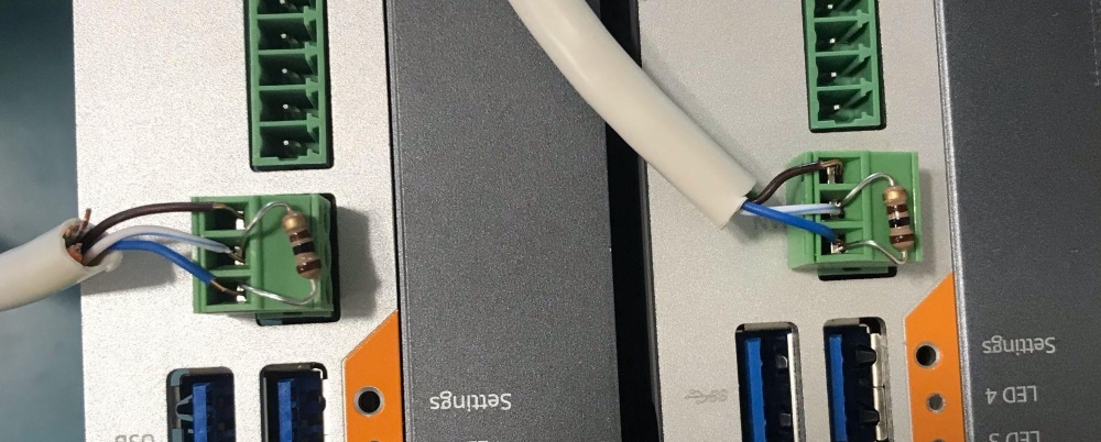
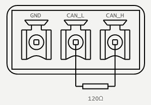
The K300 and K700’s internal CAN device should be attached directly to a CAN Bus, but features no internal termination. Because of this, for proper operation, it may be required to implement an external termination resistor. This resistor should match the nominal impedance of the cable; typically 120Ω, which complies with ISO 11898.
Using the Microcontroller CLI utility to send CAN Messages
Sending CAN messages from Windows to Linux system
After downloading and extracting the Windows directory from the Microcontroller Utility, open command prompt and navigate to the directory containing the Karbon.exe CLI utility. From here you can use the command karbon.exe raw devices
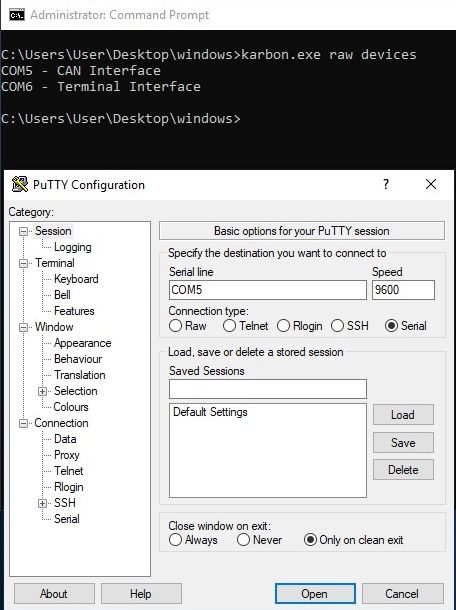
We can then use PuTTY to open the CAN interface port and now the PuTTY terminal is listening to the CAN interface of the Microcontroller.
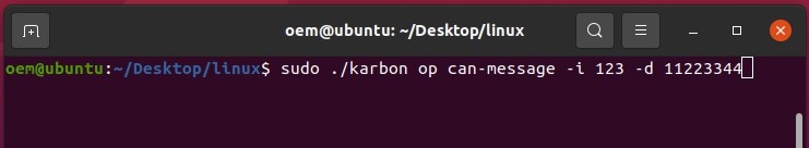
To prep a Linux system to receive these messages, we can extract the Karbon MCU utility’s Linux directory and navigate to it. Running the Karbon utility with sudo, we can send normal CAN Frames over the systems CAN Bus using the sudo ./karbon op can-message -i 123 -d 11223344 command
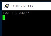
The Windows machine’s PuTTY Window will receive and present the sent CAN message
Sending CAN messages from Linux to Windows system
The Linux Microcontroller CLI utility can report which /dev/ address is handling CAN communication with the command sudo ./karbon raw devices
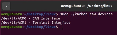
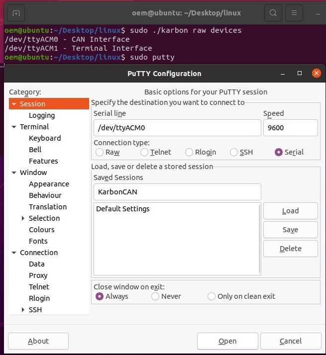
The CAN interface can be opened with an elevated PuTTY command to listen for CAN messages.
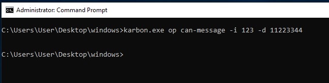
On the Windows system using an elevated command prompt, CAN messages can be sent utilizing the karbon.exe op can-message -i 123 -d 11223344 command.
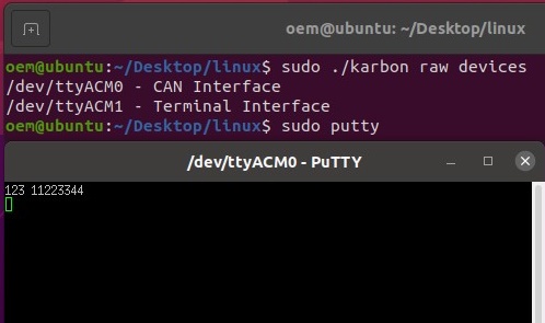
The CAN message will show up on the Linux system’s PuTTY window
Microcontroller Utility
The can subcommand supports interfacing with and controlling the onboard CAN device. This includes sending and receiving CAN messages and setting the baudrate of the CAN Bus. This module requires the CAN device be configured standard operational mode. The mode of the CAN device is controlled by the can-mode configuration parameter.
The CAN device does not support internal termination, and should be externally terminated when connected to a CAN bus.
Using SLCAN
The K300 and K700 platforms also support processing CAN commands using an slcan compliant parser. To get up and running with slcan on a K300 or K700 running Ubuntu, start by installing can-utils:
$ sudo apt install can-utils
Then detect and set up the system, for example:
slcan_setup.sh
#! /bin/bash

# ASCII Command vs CAN Bitrate
# s0 --- s1 --- s2 --- s3 --- s4 --- s5 --- s6 --- s7 --- s8
# 10     20     50     100    125    250    500    800    1000  Kbits/s
BAUD=8

# Name of slcan device to attach
DEV=can0


# Detect correct port for device interfaces
TERM_PORT=$(ls -l /dev/serial/by-id/ | grep 1fc9_00a3 | sed 's/.*\///g' | awk '{if(NR==2) print $0}')
CANB_PORT=$(ls -l /dev/serial/by-id/ | grep 1fc9_00a3 | sed 's/.*\///g' | awk '{if(NR==1) print $0}')

# Start or stop the service
while getopts ":ks" opt; do
    case $opt in
        k)
            # Stop the SLCAN service and turn off the can device
            echo "Shutting down can interface..."
            sudo ifconfig $DEV down 2> /dev/null
            sudo pkill slcand

            sudo slcand -c /dev/"$CANB_PORT"
            sudo pkill slcand
            ;;
        s)
            # Open the can device, and start the slcan service.
            echo "Terminal interface on: $TERM_PORT"
            echo "CAN Bus  interface on: $CANB_PORT"

            # Set the mode to slcan
            echo -ne "set can-mode slcan" > /dev/$TERM_PORT

            echo "Attaching slcan device..."

            # Attach to the port with slcand
            sudo slcand -s$BAUD -o /dev/"$CANB_PORT" $DEV

            # Give interface time to come up
            sleep .25

            # Enable the inteface
            sudo ifconfig $DEV up
            sudo ifconfig $DEV txqueuelen 1000

            echo "Interface is set up."
            ;;
        \?)
            echo "Invalid option: -$OPTARG" >&2
            exit 1
            ;;
        :)
            echo "Option -$OPTARG requires an argument." >&2
            exit 1
            ;;
    esac
done
The system is now ready to send and receive can messages using can-utils:
$ cansend can0 123#11223344
$ candump can0
By default, the can subcommand will first check the operational mode before sending a command. Because this is slower than just sending or receiving can messages, and requires access to the terminal port, it can disabled with the --nocheck flag.
Don’t check can mode
$ karbon can -n <COMMAND>
Additionally all can operations support setting the baudrate before processing the command. This requires access to the terminal serial interface, and does not change the baudrate that will be loaded at system boot. If no baudrate is specified, the last transmitted baudrate will continue to be used.
Specify can baudrate
$ karbon can -b 500 <COMMAND>
The baudrate is specified in Kbits/s, and supports setting rates from 100-1000.
Can Commands
The Microcontroller CLI supports sending and receiving can messages with two commands: send and dump.
Send
The send command supports sending standard, extended, and remote frames. All messages require an id. Standard and extended frames also require data. Standard frames are sent by default, while extended and remote frames can be sent by using the corresponding flag.
Usage
$ karbon can send [FLAGS] [OPTIONS] <identifier> [data]
| Argument | Description | Type |
|---|---|---|
data | The data to be transmitted, represented as an up-to eight byte hex string. Passed data will be checked for validity before transmission. This argument is required, except when sending remote request frames (-r).Example$ karbon can send 123 1122334455667788 | arg |
identifier | The ‘id’ of the can frame. Should be specified as hex string from 1-7FF for standard frames, and 1-1FFFFFFF for extended frames.Lower numbered frames will have priority during message arbitration, and by default, the id will be interpreted as a standard frame id.Validity checking will be performed against the hex string and id range. | arg |
extended | Send message in extended frame format. Supports larger id range.Example$ karbon can send -e 999 11223344 | flag |
length | Length of data to be transmitted. If not specified, the data length will be automatically determined.Example$ karbon can send -l 3 123 112233 | opt |
remote | Send a remote frame. When specified, data is not required.Example$ karbon can send -r 123 | flag |
Validity Checking
The send command’s id and data arguments are specified as strings, and parsed into hexadecimal. Because of this, validity checking is performed against the specified ID and data, before the command is passed on to the microcontroller. In psuedo-code the checks performed are as follows:
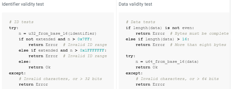
Additionally, it is acceptable to specify id or data with a leading 0x, which will simply be trimmed before data validation is performed.
Dump
The dump command supports reporting all received CAN messages. Messages may be filtered by id, and the time between frames can be recorded.
By default, the messages will be formatted and printed to stdout, but the data can also be reported in csv format and/or saved to file.
For instance, to print all messages to the terminal along with their time delta, run:
$ karbon can dump -d
Or to log only messages with a matching id to messages.csv, run:
$ karbon can dump -d -c -f 123 7FF -- messages.csv
Usage
karbon can dump [FLAGS] [OPTIONS] [--] [output]
| Argument | Description | Type |
|---|---|---|
csv | Format the output as a csv. Does not redirect output from stdout. Header will be included as id,len,data or as id,len,data,delta.Example$ karbon can dump -c id,len,data 123,4,11223344 | flag |
delta | Log the time delta between frames. Times will be reported as floating point seconds; 1.001 is 1001 milliseconds.Time delta is calculated at the host, and should not be considered a perfect representation of time between frames.Example$ karbon can dump -d id [l] data delta 123 [4] 11223344 2.907689 7FF [4] ABCD 3.386151 123 [4] 11223344 6.232194 00000999 [8] 1122334455667788 0.000519 | flag |
filter | A list of CAN frame identifiers to match received messages against. All other messages will be discarded.ImportantExtended IDs should be specified in their full form, including leading zeroes. E.g. 00000999 not 999.Example$ karbon can dump -f 123 1FFFFFFF 00000999 3AA | opt |
output | The output location for printing CAN frames. Defaults to stdout when not specified. | arg |