
AC101
Rackmount Edge Server
1- Product Overview
1.1- Introduction
The Axial AC101 is a high-performance 1U edge server designed for robust and demanding applications. It features Intel's 13th Gen Alder Lake-S processors, supports up to 128GB of DDR5 memory, and offers extensive connectivity options including 1GbE and 10GbE networking ports. The system is built to support a full-height, full-length PCIe Gen 4.0 x16 expansion card up to 150W, making it suitable for GPU-intensive workloads. With integrated remote management capabilities via a dedicated BMC/IPMI port and a durable chassis, the AC101 is engineered for reliability and performance at the edge.


1.2- Safety
Safe use and installation instructions
Install the device securely. Be careful handling the device to prevent injury and do not drop.
Equipment is intended for installation in a Restricted Access Area.
Elevated Operating Ambient - If installed in a closed or multi-unit rack assembly, the operating ambient temperature of the rack environment may be greater than room ambient. Therefore, consideration should be given to installing the equipment in an environment compatible with the maximum ambient temperature (Tma) specified by the manufacturer.
Reduced Air Flow - Installation of the equipment in a rack should be such that the amount of air flow required for safe operation of the equipment is not compromised.
Mechanical Loading - Mounting of the equipment in the rack should be such that a hazardous
condition is not achieved due to uneven mechanical loading.
Circuit Overloading - Consideration should be given to the connection of the equipment to the supply circuit and the effect that overloading of the circuits might have on overcurrent protection and supply wiring. Appropriate consideration of equipment nameplate ratings should be used when addressing this concern.
Reliable Earthing - Reliable earthing of rack-mounted equipment should be maintained. Particular attention should be given to supply connections other than direct connections to the branch circuit (e.g. use of power strips).
Ambient operating temperature must be between 5 °C to 40 °C with a non-condensing relative humidity of 8-85%.
The device can be stored at temperatures between -40 °C to 70 °C.
Keep the device away from liquids and flammable materials.
Do not clean the device with liquids. The chassis can be cleaned with a cloth.
Allow at least 2 inches of space around all sides of the device for proper cooling. If the device is mounted to a vertical surface then recommended device orientation is so that heatsink fins allow air to rise unobstructed. Alternative orientations may result in reduced operational temperature range.
This device is intended for indoor operation only.
Install the device only with shielded network cables.
Service and repair of the device must be done by qualified service personnel. This includes, but is not limited to, replacement of the CMOS battery. Replacement CMOS battery must be of the same type as the original.
Proper disposal of CMOS battery must comply with local governance.
Product must only be connected to a certified router, switch or similar network equipment.
Product is intended for indoor use only.
Product cannot be connected to the public network. \
WARNING: There is danger of explosion if the CMOS battery is replaced incorrectly. Disposal of battery into fire or a hot oven, or mechanically crushing or cutting of a battery can result in an explosion.

Précautions et guide d’installation
Ne pas ouvrir ou modifier l'appareil. L'appareil utilise des composants conformes aux réglementations FCC et EC. La modification de l'appareil peut annuler ces certifications.
Installez l'appareil en toute sécurité. Manipulez l'appareil avec précaution pour éviter de vous blesser et ne le laissez pas tomber.
L'équipement est destiné à être installé dans une zone à accès restreint.
Température ambiante de fonctionnement élevée - En cas d'installation dans un rack fermé ou à plusieurs unités, la température ambiante de fonctionnement de l'environnement du rack peut être supérieure à la température ambiante de la pièce. Par conséquent, il convient de veiller à installer l'équipement dans un environnement compatible avec la température ambiante maximale (Tma) spécifiée par le fabricant.
Débit d'air réduit - L'installation de l'équipement dans un rack doit être telle que la quantité de débit d'air requise pour un fonctionnement sûr de l'équipement ne soit pas compromise.
Chargement mécanique - Le montage de l'équipement dans le rack doit être tel qu'un condition n'est pas atteinte en raison d'une charge mécanique inégale.
Surcharge de circuit - Il convient de tenir compte de la connexion de l'équipement au circuit d'alimentation et de l'effet que la surcharge des circuits pourrait avoir sur la protection contre les surintensités et le câblage d'alimentation. Une prise en compte appropriée des valeurs nominales de la plaque signalétique de l'équipement doit être utilisée pour répondre à cette préoccupation.
Mise à la terre fiable - Une mise à la terre fiable de l'équipement monté en rack doit être maintenue. Une attention particulière doit être accordée aux raccordements d'alimentation autres que les raccordements directs au circuit de dérivation (par exemple, utilisation de multiprises).
La température ambiante de fonctionnement doit être comprise entre 5 °C et 40 °C avec une humidité relative sans condensation de 8 à 85 %.
L'appareil peut être stocké à des températures comprises entre -40 °C et 70 °C.
Gardez l'appareil à l'écart des liquides et des matériaux inflammables.
Ne nettoyez pas l'appareil avec des liquides. Le châssis peut être nettoyé avec un chiffon.
Laissez au moins 2 pouces d'espace autour de tous les côtés de l'appareil pour un refroidissement correct. Si l'appareil est monté sur une surface verticale, l'orientation recommandée de l'appareil est de sorte que les ailettes du dissipateur thermique permettent à l'air de monter sans obstruction. Des orientations alternatives peuvent entraîner une plage de températures de fonctionnement réduite.
Cet appareil est destiné à une utilisation en intérieur uniquement.
Installez l'appareil uniquement avec des câbles réseau blindés.
L'entretien et la réparation de l'appareil doivent être effectués par un personnel qualifié. Cela inclut, mais sans s'y limiter, le remplacement de la batterie CMOS. La batterie CMOS de remplacement doit être du même type que celle d'origine.
L'élimination appropriée de la batterie CMOS doit être conforme à la gouvernance locale.
Le produit doit uniquement être connecté à un routeur, un commutateur ou un équipement réseau similaire certifié.
Le produit est destiné à une utilisation en intérieur uniquement.
Utilisez uniquement des connecteurs répertoriés UL pour la connexion aux panneaux de fusibles automobiles.
Le produit ne peut pas être connecté au réseau public.
ATTENTION: Il existe un risque d'explosion si la pile CMOS n'est pas remplacée correctement. L'élimination de la batterie dans le feu ou dans un four chaud, ou l'écrasement ou le découpage mécanique d'une batterie peut entraîner une explosion.
1.3- Box Contents & Accessories
The following accessories are included with every system:
PSU filler (2RALXX5862A1)
Nvidia 9.5” GPU mounting kit w/ screws (2RALXX5861A1)
SSD cable brackets (2RALXX5859A1)
Spare motherboard standoffs (2RALXX282300)
Spare PCIe riser screws (2RALXX585800)
Cable management ties
Security bezel key
If additional items were purchased, such as rail mounting kits/brackets, they will be boxed separately.
1.4- Product Specifications
Variants
AC101 - High-Performance 1U with 150W PCIe 4.0 x16 Expansion
Processor
Intel 13th Gen Alder Lake-S (LGA1700) Core i3, i5, i7 & i9 up to 24-core 32-thread i3-13100E or TE, i5-13500E or TE, i7-13700E or TE, i9-13900E or TE
125W PL2 (Power Level 2)
Memory
Support up to 4x DDR5-4800 UDIMMs (non-ECC or ECC) Up to 128GB total memory Maximum operational speed: 4400 MT/s
Chipset
Intel W680
Integrated Graphics
Intel UHD Graphics 730 (i3) or 770 (i5, i7, i9)
Front I/O
2x USB 3.2 Gen 1 Type A 1x Power Button / LED (White) 1x ID button / LED (Blue)
Rear I/O
1x 1GbE Dedicated Management (BMC/IPMI) 2x 1GbE LAN Intel i210 2x 10GbE LAN Intel X710 2x USB 3.2 Gen 1 Type-A 1x DisplayPort 1x HDMI 1x VGA 1x DB9 (COM) 1x ID button / LED (Blue)
Expansion & Storage
1x M.2 2280/2260/2242/2230 M-key (PCIe Gen 3 x4) 1x PCIe Gen 4 x16 Full Height, Full Length slot (up to 150W) Up to 4x 2.5” Drives (NVMe or SATA)
Special Features
ASPEED AST2600: Full Web UI, iKVM, vMedia support 1/10 Network Controller Sideband Interface (NC-SI) Optional TPM 2.0 module (Infineon SLB9670) or Intel PTT (Native) Chassis Intrusion Detection Security Bezel Secure Boot
Operating Systems
Microsoft Windows 10 IoT Enterprise 2021 LTSC (Value/High End) 64-bit Microsoft Windows 11 Professional 64-bit Red Hat Enterprise Linux 8.8 - 8.x Red Hat Enterprise Linux 9.2 - 9.x Ubuntu Desktop 22.04 Intel IoT for 13th Gen Intel Core processors Ubuntu Server 22.04 Intel IoT for 13th Gen Intel Core processors
LAN Controllers
2x Intel i210 Controllers (2x 1GbE ports) 1x Intel X710 Controller (2 x 10GbE ports)
Power Supplies
Up to 2 PSUs with PMBUS monitoring, 100~240 VAC, 5A, 50-60Hz input 450W Gold 750W Platinum
Dimensions (WxHxD)
430 x 43.5 x 515mm (16.9 x 1.7 x 19.7”) without Security Bezel 483 x 43.5 x 534mm (19.0 x 1.7 x 21.0”) with Security Bezel
Weight
System Maximum: 10.02 kg (22.1 lbs) Shipping Maximum: 12.88 kg (28.4 lbs)
Operating Temp.
5°C ~ 40°C (ASHRAE A3 Operating Temperature) Maximum ambient temperature decreases by 1°C for every 175m (574 ft) increase in altitude above 900m (2,953 ft)
Storage Temp.
-40°C ~ 70°C
Operating Humidity
8~85% Relative, non-condensing Maximum dew point 24°C
Storage Humidity
0~95% Relative, non-condensing Maximum dew point 24°C
Shock & Vibration
ISTA 6-FEDEX-A

FCC 47 CFR Part 15 Subpart B (Class A) CAN ICES-003(A) / NMB-003(A) (Class A) (Class B upon request)

EN 63268-1 CISPR 32/EN 55032 (Class A; Class B upon request) CISPR 35/EN 55035 Radio Equipment Directive (2014/53/EU)

RoHS 3 (2015/863/EU)

WEEE Directive (2012/19/EU)

IEC/EN/UL 62368-1 (UL File No. E490677)
Americas
Canada, United States
Europe
Austria, Belgium, Bulgaria, Croatia, Czech Republic, Cyprus, Denmark, Estonia, Finland, France, Germany, Greece, Hungary, Iceland, Ireland, Italy, Latvia, Lithuania, Liechtenstein, Luxembourg, Malta, Norway, The Netherlands, United Kingdom, Poland, Portugal, Romania, Slovakia, Slovenia, Spain, Sweden
Asia
Available countries upon request
Other countries may be available, contact us to learn more
1.5- System Identification & Labels
System Label
The system label is located on the bottom of the chassis. It contains the following information:
System Model
OnLogic Serial Number
Regulatory & Compliance Certification Logos

Front Service Label
On the front of the chassis, there is a retractable product information label containing pertinent product information such as:
System Model
OnLogic Serial Number
BMC MAC addresses

2- Technical Specifications
2.1- External Features
Front I/O

Front LEDs & Buttons

Power
White
Device is on
Device is off
-
ID (Identification)
Blue
ID indicator asserted
ID indicator is deasserted
ID indicator is blinking
RST (Reset)
-
-
-
-
The ID LED/Button is available to assist with locating the system. ID may be physically turned On / Off by physically pressing the ID button. ID may also be turned On, Off, or set to Blink from the Baseboard Management Controller (BMC) Web UI.
RST Button will reset the system.
Rear I/O

2.2- I/O Definitions
Network Ports
The Axial AC101 features the following onboard Ethernet ports:

1GbE Dedicated BMC Port LEDs

1GbE Networking Port LEDs

10GbE Networking Port LEDs

USB Ports
There are 4 USB 3.2 Gen 1 Type A ports on the Axial AC101 Edge Server.
Two ports are on the front of the system.
Two ports are on the rear of the system.
All USB ports support USB 2.0 connectivity.
DisplayPort Video
There is one full-size DisplayPort (1.4a) located on the back of the Axial AC101 Edge Server.
HDMI Video
There is one full-size HDMI (2.0b) port located on the back of the system.
VGA Video
There is one VGA port located on the back of the system. HDMI, DisplayPort, VGA, COM and USB ports are only for setup use.
2.3- Internal Connectivity

Note: SATA Ports are labeled in accordance with how they are enumerated in BIOS. See SATA Headers section for additional detail.
M.2 2280/2260/2242/2230 M-key
This expansion slot is capable of supporting PCIe Gen 3 x4 and is routed directly to the W680 PCH. This slot is designed to support NVMe storage drives.
TPM Header
The Axial AC101 supports an optional discrete TPM 2.0 module.
Drive Headers, Labeling, and Recommended Population
SATA Headers
There are four SATA data headers on the motherboard. The data ports support SATA III 6Gbps storage devices.

In BIOS, the SATA ports are enumerated starting with SATA_4 (e.g. sSATA0 = SATA_4, sSATA1 = SATA_5, sSATA2 = SATA_6, sSATA3 - SATA_7).
When in an operating system, drive enumeration will start with the lowest connected SATA port number.
Note: sSATA (or SSATA) is an acronym for secondary-Serial Advanced Technology Attachment and is referencing the connectivity method to the system chipset.
OCuLink Headers
There are four OCuLink headers on the motherboard that support PCIe 4.0 x4 connections to enable NVMe drives.

When in an operating system, based on the PCIe topology, drive enumeration will be inverted from the OCuLink silkscreen labeling as per the following table:
OCU4
Drive 0
OCU3
Drive 1
OCU2
Drive 2
OCU1
Drive 3
SSD Physical Location
The SSD Drive Bays for this system are labeled as follows:

Drive Population
The following drive population recommendations are provided to ensure consistency of connectivity, operation, and OS drive enumeration aligned to physical drive bay locations.

PCIe Gen 4.0 x16 Slot
The Axial AC101 features one PCIe Gen 4.0 x16 connector accessible via a right angle riser card. The slot's edge power draw supports up to 75W. Adapters up to 150W are supported using the optional PCIe 6-Pin/8-Pin auxiliary power header.
DDR5 UDIMM Slots
The system supports up to four DDR5 UDIMM slots rated up to 4400MHz.
4400MT/s @ 2DPC-1DIMM
4000MT/s @ 2DPC-2DIMM 1R
3600MT/s @ 2DPC-2DIMM 2R
The system will support both ECC and non-ECC memory with all supported CPU options.
Supported Memory Modes
The Integrated Memory Controller (IMC) supports single-channel and dual-channel modes, depending on DIMM population.
Single-Channel Mode: Used when DIMMs are installed in either Channel A or Channel B, but not both.
Dual-Channel Mode – Intel® Flex Memory Technology Mode: In this mode, memory is divided into a symmetric and asymmetric zone. As per Intel documentation:
“The symmetric zone starts at the lowest address in each channel and is contiguous until the asymmetric zone begins or until the top address of the channel with the smaller capacity is reached. In this mode, the system runs with one zone of dual-channel mode and one zone of single-channel mode, simultaneously, across the whole memory array.”

Dual-Channel Symmetric Mode (Interleaved Mode): Dual-Channel Symmetric mode is fully interleaved and provides the maximum performance. The Axial AC101 will default to Dual-Channel Symmetric mode when both Channel A and Channel B DIMM connectors are populated in any order, with the total amount of memory in each channel being the same. When both channels are populated with the same memory capacity and the boundary between the dual channel zone and the single channel zone is the top of memory, IMC operates completely in Dual-Channel Symmetric mode.
DIMM Population Requirements
Only DDR5 DIMMs may be installed.
Memory frequency will not exceed that of the lowest frequency DIMM installed.
Dual Channel Memory Mode is only supported with 2 or 4 DIMMs installed (split equally between channels as indicated in the DIMM Population table).
The following population order is recommended to maximize performance:

2.4- Motherboard
Layout & Component Overview


2.5- Power Management
Supported Power Supplies
The system supports two redundant power supplies, which may either be 450W or 750W. These power supplies are hot-swappable, meaning they can be replaced while the system is running without interrupting its operation.

It is important to note that the two power supplies must be of the same wattage. Mixing power supplies of different wattages is not allowed. Please ensure that both power supplies are of the same wattage before installing them into the system.
If you need to replace a failed power supply, simply remove the failed unit and insert a new one of the same wattage. The system will automatically recognize the replacement power supply and bring it online to restore redundancy.
IMPORTANT: When utilizing 150W PCIe adapters (such as GPUs), a 750W power supply is recommended due to momentary power spikes (exceeding 150W) that may occur. When these power spikes occur, the power consumption of the PCIe adapter combined with power draw of other system components may exceed the available power of a 450W supply.
Power Redundancy
The power supplies in this system are fully redundant in a primary/backup mode. This means that the two power supplies work in parallel, with one power supply acting as the primary source of power and the other as a backup.
In normal operation, the primary power supply is responsible for supplying power to the system, while the backup power supply remains idle. If the primary power supply fails, the backup power supply automatically takes over, ensuring that the system continues to receive power without interruption.
The power supplies are designed to work seamlessly together, with the primary power supply handling the majority of the load and the backup power supply providing additional power as needed. This redundancy ensures that the system can continue to operate even if one power supply fails, providing a high level of reliability for critical systems.
If a power supply failure occurs, the alerts will be presented via the Baseboard Management Controller (BMC) or an audible alarm may occur. If this happens, the failing supply can be serviced while the system remains operational on the backup power supply. Once the replacement power supply is installed, the system will automatically detect it and bring it online, restoring full redundancy.
Wake-Up Events
The Axial AC101 supports multiple power states and wake-up events.
Power Button
Deep S5 , S5, S4
PCIE/LAN
S5*, S4, S3
Must be enabled in BIOS
USB Keyboard/Mouse/Remote
S3
Must be enabled in BIOS
RTC Alarm
S5
Must be enabled in BIOS
* Onboard Intel® X710 Network controller only supports wake from S5
Note: The Power LED is off when the system is in S4 sleep state or powered off (S5).
Auto Power On Configuration
The Axial AC101 can be configured to turn on automatically when power is connected. This is useful for power outage recovery or if the unit is mounted in a hard to reach location. You can adjust Auto Power On settings by following the steps listed below.
Power on the system and press F2 a few times to access the BIOS
Navigate to Server Mgmt > BMC Tools
Locate Restore AC Power Loss setting
This can be changed to any of the following states:
Power Off: The system will remain off when power is restored
Last State: The system will recover to the state it was in before the power loss event (i.e. If the unit was off, it would stay off. if the unit was powered on, it would power back on.)
Power On: The system will power on after any power loss event
Press F10 to Save & Exit
2.6- Thermals & Cooling
The Axial AC101 Edge Server is designed to operate and function across a wide temperature (5 to 40°C) and humidity range (8 to 85% RH non-condensing). The following sections describe the thermals and cooling capabilities and behavior of the system.
System Fans and Airflow Direction
The Axial AC101 Edge Server has five 40x40x56mm counter rotating system fans, which can be independently controlled and configured via the Baseboard Management Controller (BMC) relative to the supported system temperature sensors. The default fan duty and configuration settings have been validated to operate in accordance with the supported temperature range (up to 40°C). If the ambient operating temperature is tightly controlled, additional fan configuration optimizations may be manually adjusted to optimize acoustics and reduce power consumption. For additional information pertaining to manual fan configuration settings, please consult the Axial Edge Server BMC Manual.
The power supply fans operate independently and have their own closed-loop cooling algorithm.

Temperature Sensors
Sensor data is available for several onboard components.

TEMP_MB
54
55
TEMP_CPU
TjMax - 1
TjMax
TEMP_VR
99
100
TEMP_CARD_SIDE
69
70
TEMP_X710
99
100
TEMP_TR1
65
TEMP_M.2
70
TEMP_GPU
92
93
Default Fan Settings
The system uses a closed-loop thermal algorithm to balance performance, acoustics, and power consumption.
Fan Zone Assignments
Fan Zone 1 - CPU Area
Assigned Sensor: TEMP_CPU
Assigned Fans: FAN3, FAN4, FAN5

Behavior: As per the default configuration settings, the system fans will increase duty cycle at 3% increments every 1 seconds when the CPU temperature is at or above 80°C. When the temperature drops below 75°C, the system fan duty cycle will reduce 3% every 3 seconds.
Ramp Up Temp (°C)
80
Ramp Up Interval (sec)
3
Ramp Up Duty (%)
1
Ramp Down Temp (°C)
75
Ramp Down Interval (sec)
3
Ramp Down Duty (%)
3
Ramp Threshold (°C)
0

Fan Zone 2 - PCIe / GPU Area
Assigned Sensor: TEMP_GPU
Assigned Fans: FAN1, FAN2
Behavior: As per the default configuration settings, the system fans will increase duty cycle at 3% increments every 2 seconds when the GPU temperature is at or above 86°C. When the temperature drops below 76°C, the system fan duty cycle will reduce 3% every 1 second.

Note: GPU temperature sensing is only supported with Nvidia professional grade GPUs.
Additional Fan Defaults
The default system idle duty cycle is 5%.
Upon System Fan Failure or BMC Firmware Update, System Fans will ramp to maximum speed.
Thermal Performance and Validation
As previously noted, the default fan duty and configuration settings have been validated to operate in accordance with the supported temperature range (up to 40°C) as per the following test scenario and results.
Test Conditions
Temperature Range: 5ºC to 40°C (+5)
System Configuration:
i9-13900TE Processor (125W PL2)
Performance-core Max Turbo Frequency: 5.00 GHz
Efficient-core Max Turbo Frequency: 3.90 GHz
Performance-core Base Frequency: 1.00 GHz
Efficient-core Base Frequency: 800 MHz
2 TB PCIe Gen4 x4 m.2 Storage
4 PCIe 4.0 2.5” Storage Drives
128GB DDR5 Memory
Nvidia T1000 GPU
Max Boost Frequency: 2100 MHz
Base Frequency: 1065 MHz
Workload Applications/Test:
Memory 80% workload with PassMark BurnInTest
Storage 80% workload with PassMark BurnInTest
3D Graphics 80% workload with PassMark BurnInTest
Processor loaded 100% with Intel XTU
Discrete GPU loaded with Nvidia Nbody
Test Results
The Axial AC101 system sustained a full processor workload and 80% workloads on memory, storage and 3D graphics, along with executing an Nbody simulation through its full rated temperature range without throttling and while maintaining greater than base clocks on all processor cores and GPU cores. During the test sequence numerous points throughout the system were monitored to ensure adequate cooling was provided to components in the system. The system was also tested 5ºC above and below its rated temperature range to help classify performance outside of the rated temperature range.


2.7- Block Diagram

3- Installation & Mechanical
3.1- Dimensions


3.2- Mounting
Mounting Hardware
The Axial AC101 Edge Server has been designed with flexibility in mind and can be mounted in different ways. As the system is designed to meet industry standard 19” Electronic Industries Alliance (EIA) racks, there are multiple rack mounting rail kits available. Additionally, the system may also be wall mounted using the OnLogic wall mount kit.
Rack Mounting
The Axial AC101 Edge Server has been designed to support standard 19" EIA rack mounting, which is a common form factor used in data centers and server rooms. To accommodate different rack depths, the system supports 23" and 28" rail kits that can be used to securely mount the server in the rack. These rail kits are easy to install and include all the necessary hardware for attachment into the rack.
Rackmount 23" Ball Bearing Slide Rails
The 23" Ball Bearing Slide Rails are an optional accessory designed to enhance the functionality and ease of use of the Edge Server. These slide rails are designed to be used with standard 19" EIA racks and allow for easy installation and removal of the server from the rack. The ball bearing design ensures smooth and effortless sliding motion, while the sturdy construction provides a secure and stable platform for the server. With these slide rails, you can easily access the server for maintenance or upgrades without the need for complex disassembly or cumbersome lifting.
The 23” Ball Bearing Slide rail kit can be chosen at time of configuration based on the rack depth requirements.
Mounting Hole: Square, Rack Depth Range (front to back flange):597mm (23.5in) to 927mm (36.5in)
\

Rackmount 23" Ball Bearing Cable Management Arm Slide Rail Kit
The 23" Ball Bearing Cable Management Arm Slide Rail Kit is an optional accessory that enhances the standard ball bearing slide rail options by providing a cable management arm to neatly organize and secure cable connections to the Edge Server system while still supporting easy removal of the server from the rack for maintenance and upgrades.
The 23” Ball Bearing Slide rail kit can be chosen at time of configuration based on the rack depth requirements.
Mounting Hole: Square, Rack Depth Range (front to back flange): 597mm (23.5in) to 927mm (36.5in)
\


Rackmount 28" Simple Locking Ball Bearing Slide Rails
The 28” Simple Lock Ball Bearing Slide Rails are an optional accessory designed to enhance the functionality and ease of use of the Edge Server. These slide rails are designed to be used with standard 19" EIA racks and allow for easy installation and removal of the server from the rack. The ball bearing design ensures smooth and effortless sliding motion, while the sturdy construction provides a secure and stable platform for the server.
With these slide rails, you can easily access the server for maintenance or upgrades without the need for complex disassembly or cumbersome lifting.
The simple locking mechanism allows for quick mounting into a rack without the use of any tools.
The 28” Simple Lock Ball Bearing Slide rail kit can be chosen at time of configuration based on the rack depth requirements.
Mounting Hole: Square, Rack Depth Range (front to back flange): 609mm (24in) to 921mm (36.2 in)
\

Wall Mounting
Wall mount kit
The Axial AC101 Edge Server wall mount kit is made of sturdy metal and designed to securely hold the server in place against a wall. This optional accessory includes the necessary wall mounting brackets and hardware to flexibly mount the Axial AC101 Edge Server system where a rack is not available or practical.


3.3- System Servicing
System Access
The AC101 can be opened by the user. This does not void the warranty, however, any damage caused by doing so will not be covered.
This section provides guidance for accessing and replacing internal components. Before performing any service, ensure the system is powered down and disconnected from its power source unless performing a hot-swap operation as described below.
Front panel access & Serial label

Unlock the front panel using the included keys in the accessory box
The front panel can now be removed. Pull from the left side (the side with the lock) first.

You now have access to the power button, USB ports, and serial label tag. Pull the tab for easy access to your unit’s serial number and BMC MAC information. A second label can be found on the bottom of the unit as well.

Opening the System
The chassis lid features a two-point locking mechanism. The first is a top latch with a tamper-resistant screw, and the second is a thumbscrew at the rear of the system. Both must be unlocked to remove the lid.
Make sure the system is disconnected from power, monitor, and all peripheral connections before proceeding.
Loosen the black retaining screw on the back of the system.

Unlock the lid latch and press the blue button to release it. Pull back on the latch arm to loosen the lid.

Th lid can now be removed. The internals of the system can be accessed for maintenance and troubleshooting.

Hot-Swappable Components
Power Supplies: The redundant 450W or 750W power supplies are hot-swappable. A failed unit can be replaced while the system is running without interrupting operation. Ensure the replacement PSU is the same wattage as the remaining unit.
Other Replaceable Components
Memory (DIMMs): See section 2.3 for DIMM population rules and physical locations.
Storage Drives: See section 2.3 for SATA/NVMe drive locations and population guidelines.
PCIe Cards: See section 2.3 for PCIe slot details.
Servicing PCIe & GPU
Adding/Removing PCIe card
Additional motherboard ports and troubleshooting may require access under the PCIe card (if installed). Follow these steps to safely remove the PCIe card and support bracket.
Remove the retention screw on the back of the system (circled in Orange). If you have a longer PCIe card, such as some GPUs, it may have an extra supporting bracket. Remove the x2 screws located near the back of the PCIe card (circled in Blue).
Remove the PCIe card by lifting straight up. Be careful of any cables running around the support bracket or connected to the card. You can pull up using the hole in the metal bracket.

3.4- CAD & Drawings
4- Software & Firmware
4.1- BIOS/UEFI
The BIOS/UEFI provides critical low-level system configuration.
For complete details on BIOS/UEFI configuration, refer to the official User Manual:
Axial AC100 Series BIOS/UEFI Manual4.2- Remote Management (IPMI/BMC)
The Axial AC101 includes a dedicated Baseboard Management Controller (ASPEED AST2600) for comprehensive remote management. This allows for out-of-band control of the server, including power cycling, health monitoring, virtual media access, and KVM functionality, all accessible through a web UI via the dedicated 1GbE Management port. The BMC also controls fan curves and logs system events like chassis intrusion. For detailed instructions on configuration and usage, please consult the separate BMC Manual:
Axial Edge Server BMC ManualChanging the BMC Chassis ID (Flex GPU Support)
The following outlines how to configure the Axial AC101 BMC firmware to support Intel Flex dGPUs. The BMC's default chassis ID is set for Nvidia GPUs; changing it enables support for Intel dGPUs and their respective sensors and communication protocols.
Via BMC Web UI (Recommended)
Change Chassis ID:
Log in to the BMC Web UI.
Navigate to
Settings>Chassis ID Select.From the dropdown, select "Intel_Flex_GPU" and click
Save.Confirm the BMC reset when prompted.
Verify Change:
After the BMC reboots, log back into the Web UI.
Confirm "Intel_Flex_GPU" is displayed in the dropdown menu.
On the
Sensorpage, verify "TEMP_GPU" and "PWR_GPU" sensors report values if an Intel Flex GPU is installed and present.
Revert to Default (NVIDIA dGPU Support):
From the Home screen, select
Settings, thenChassis ID Select.Toggle back to "Default" and click
Save. ClickOKwhen prompted.Note: Resetting the BMC to default does not change the Chassis ID.
Via IPMITOOL (CLI - Debug)
Commands can be executed remotely (local host OS not required). Substitute variables (
$IP,$username,$password) with appropriate values. Refer to Axial AC101 BMC Manual, Section 7 for additional information.
Change Chassis ID Value:
Execute:
ipmitool -H $IP -I lanplus -U $username -P $password raw 0x3a 0xaa 0x49 0x6e 0x74 0x65 0x6c 0x5f 0x46 0x6c 0x65 0x78 0x5f 0x47 0x50 0x55Apply Chassis ID (Reboot BMC):
ipmitool -H $IP -I lanplus -U $username -P $password raw 0x6 0x2
Verify Change:
After approximately 3 minutes (BMC reboot), run the sensor listing command:
ipmitool -H $IP -I lanplus -U $username -P $password sensor listConfirm "PWR_GPU" appears in the list.
Check Current Chassis ID:
To retrieve the current chassis ID, execute:
ipmitool -H $IP -I lanplus -U $username -P $password raw 0x3a 0xab
Revert Chassis ID to Defaults (NVIDIA dGPU Support):
Execute:
ipmitool -H $IP -I lanplus -U $username -P $password raw 0x3a 0xaa 0xffApply Chassis ID (Reboot BMC):
ipmitool -H $IP -I lanplus -U $username -P $password raw 0x6 0x2After approximately 3 minutes, verify "PWR_GPU" shows a value when an Nvidia GPU is installed.
Note: Changing the Chassis ID is persistent across BMC reboots and firmware updates.
Intel Flex GPU Driver Installation
For Ubuntu:
Follow Intel's official driver installation guide: https://dgpu-docs.intel.com/driver/installation.html
Add Required Grub Kernel Argument:
Modify
/etc/default/grubusing a text editor (e.g.,vi). Usesudoand enter your password when prompted.Edit the line beginning with "GRUB_CMDLINE_LINUX_DEFAULT", adding
pci=realloc=offinside the double-quotes, typically after "quiet splash". (If "quiet splash" is absent, that's acceptable.)Save the file and exit the text editor.
Update Grub:
sudo update-grubRestart the system.
Note: This argument ensures proper Intel Flex GPU enumeration within the Intel Core CPU architecture. This function is typically enabled by default to accommodate PCI bridge resource reallocation if BIOS allocations are insufficient for child devices.
For Windows:
Follow Intel's official instructions and download drivers from: https://www.intel.com/content/www/us/en/download/780185/intel-data-center-gpu-flex-series-windows.html
Fan Settings
The following fan settings are deviations from the Nvidia defaults that will automatically be set with BMC firmware version 1.17 when the Chassis ID is set to Intel GPU.
Closed Loop Control Table 2 (This likely refers to a table or further details within the content)
Base Fan Speed:
From the BMC Web UI –> Settings –> Fan Settings –> Fan Mode page:
Set FAN1 and FAN2 to
Customized.Set the Minimum Duty to
25.Click
Save.
Adjusting Fan Locations:
The AC101 1U chassis accommodates two PCIe Expansion fan mount points.
Configuring the Video Settings to Enable Remote Display
The current default display settings are as follows. Please refer to the screenshot where onboard VGA and Intel IGFX are disabled. When a GPU is installed, the GPU ports will be the primary display output as default.

Thcould lead to the below 2 problems:
The display signal from the GPU port is slow. This tends to lead to a lack of video signal until the BMC is fully initialized and can still take some additional time after that before a video signal is available.
When trying to connect to the device remotely via BMC, there is no video output via KVM access. The 3 BIOS settings need to be modified and then the video output will be displayed remotely. Please also refer to the screenshot below for the modifications.

Even if there are no issues, please consider setting the default settings to be BMC access friendly by enabling these settings in the BIOS.
4.3- Drivers & Downloads
Drivers
BIOS Updates
Refer to the AC101 BIOS Manual Section 5.16 – Instant Flash for update procedure.
BMC Updates
BMC Version
Release Date
Link
4.4- Operating System Compatibility & Installation
Supported Operating Systems
Microsoft Windows 10 IoT Enterprise 2021 LTSC Value (Celeron/i3/i5) - 64 Bit
Microsoft Windows 10 IoT Enterprise 2021 LTSC High End (i7/i9/Xeon) - 64 Bit
Microsoft Windows 11 Professional 64-bit
Red Hat Enterprise Linux 8.8 - 8.x
Red Hat Enterprise Linux 9.2 - 9.x
Windows 10 IoT Enterprise 2021 LTSC Licensing
Windows 10 IoT LTSC (Long-Term Servicing Channel) is a version of the Windows 10 operating system designed for use in embedded and IoT (Internet of Things) devices.
For information pertaining to the benefits of Windows 10 IoT, please refer to the following: Windows 10 IoT and its Benefits for Businesses.
The 2021 version of Windows 10 IoT LTSC comes in two licensing editions that are supported and may be preloaded on to the Axial AC101 Edge Server:
Microsoft Windows 10 IoT Enterprise 2021 LTSC Value
This version of Windows 10 IOT is suitable for systems with Intel Core-i3 and Core-i5 processors.
Microsoft Windows 10 IoT Enterprise 2021 LTSC High End
This version of Windows 10 IOT is suitable for systems with Intel Core-i7 and Core-i9
Both versions support Azure IoT Edge for Linux on Windows (EFLOW), allowing for containerized Linux workloads alongside Windows applications in Windows deployments. For additional information, see What is Azure IoT Edge for Linux on Windows from Microsoft.
4.5- RAID Configuration
The following contents will provide information on the RAID capabilities of the Axial AC101 Edge Server and guide users on how to configure RAID.
RAID (Redundant Array of Independent Disks) is a technology that allows multiple hard drives to work together as a single logical drive, providing increased performance and data redundancy. The idea behind RAID is to combine the storage capacity of multiple drives to create a larger virtual drive that appears to the operating system as a single disk.
RAID can improve system performance by distributing data across multiple drives, allowing for faster read and write speeds. Additionally, RAID can provide data redundancy by using multiple drives to store the same data, so that if one drive fails, data can still be accessed from the other drives. There are several RAID levels with different configurations and benefits, each offering varying levels of performance and data redundancy.
The Axial AC101 Edge Server supports onboard RAID via Intel® Rapid Storage Technology as supported by the Intel® W680 chipset.
Intel® RST (Intel® Rapid Storage Technology) is a software solution developed by Intel® Corporation that provides advanced storage management capabilities for Intel® chipset-based motherboards.
Prior to configuration of RAID, users are advised to back up their data before configuring RAID as the process may erase all data on the hard drives.
Supported SATA RAID Types
The following sections will discuss the various SATA RAID types that are supported on the Axial AC101 Edge Server and their respective advantages/disadvantages.
RAID 0: Striping

RAID 0 (Redundant Array of Inexpensive Disks level 0), also known as striping, is a method of combining multiple physical hard drives into a single logical volume for improved performance.
In RAID 0, data is divided into blocks and spread across two or more physical drives simultaneously. The blocks are written to the drives in a way that balances the load and optimizes performance. When data is read, the blocks are retrieved from multiple drives at the same time, increasing the read and write speed of the overall system.
An advantage of RAID 0 is its improved performance due to the parallel access to multiple drives. However, RAID 0 does not provide any fault tolerance or redundancy. If one drive fails, the entire RAID 0 volume will be lost, along with all data stored on it. Therefore, it is recommended to use RAID 0 only for non-critical data or as part of a larger backup and disaster recovery strategy.
RAID 0 requires a minimum of two drives..
For RAID 0, it is recommended to use disks of the same interface, speed, and capacity, but if the disks in a RAID 0 array have different sizes, performance may be limited and the capacity of the array will be limited by the size of the smallest disk.
RAID 1: Mirroring

RAID 1 (Redundant Array of Inexpensive Disks level 1) is a type of data storage technology that provides data redundancy and fault tolerance by creating an exact copy, or mirror, of data on two or more physical drives.
In RAID 1, when data is written to one drive, it is simultaneously written to the other drive(s), creating an exact duplicate of the data on each drive. This ensures that if one drive fails, the data can still be accessed from the remaining drive(s). The read performance of RAID 1 can be faster than that of a single drive because data can be read from multiple drives at the same time. However, the write performance is generally slower because data must be written to multiple drives.
An advantage of RAID 1 is its data redundancy and fault tolerance. If one drive fails, the data is still available on the other drive(s). Additionally, RAID 1 can be hot-swappable, meaning that if a drive fails, it can be replaced without having to shut down the system.
However, RAID 1 has some disadvantages, including lower storage capacity compared to other RAID configurations and higher cost due to the need for multiple drives. RAID 1 is recommended for applications that require high data availability and reliability, such as mission-critical systems, servers, and database applications.
RAID 1 requires a minimum of two drives.
For RAID 1, it is recommended to use disks of the same interface, speed, and capacity, but if the disks in a RAID 1 array have different sizes, performance may be limited and the capacity of the array will be limited by the size of the smallest disk.
RAID 5: Striping with Parity

RAID 5 (Redundant Array of Inexpensive Disks level 5) is a type of data storage technology that uses striping with distributed parity.
In a RAID 5 configuration, data is striped across multiple disks, with parity information distributed across all the disks. This provides fault tolerance and redundancy, allowing data to be reconstructed in the event of a single drive failure.
RAID 5 offers good performance and fault tolerance for small to medium-sized businesses, but it has a higher overhead and is more complex than some other RAID configurations. Additionally, in the event of a second drive failure, data loss can occur. RAID 5 is often used in applications that require a balance between performance, fault tolerance, and cost.
RAID 5 requires a minimum of three disks, and the capacity of one disk is used for parity information.
For RAID 5, it is recommended to use disks of the same interface, speed, and capacity, but if the disks in a RAID 5 array have different sizes, performance may be limited and the capacity of the array will be limited by the size of the smallest disk.
RAID 10: Mirrored Striped

RAID 10 (Redundant Array of Inexpensive Disks level 10), also known as RAID 1+0 or mirrored striped volumes, is a combination of RAID 1 and RAID 0. It provides both data redundancy and improved performance.
In a RAID 10 configuration, multiple pairs of disks are configured as RAID 1 arrays, where data is mirrored between each pair of disks for redundancy. The resulting RAID 1 arrays are then striped together in a RAID 0 array, where data is striped across all of the mirrored pairs for increased performance.
Data is striped across the mirrored pairs, so the capacity of the RAID 10 array is equal to half of the total capacity of the disks. For example, in a four-disk RAID 10 array with 1TB disks, the total capacity of the array would be 2TB.
RAID 10 provides both performance and redundancy benefits, as it offers the performance benefits of RAID 0 while also providing the redundancy of RAID 1. In the event of a single disk failure, the mirrored pair can continue to provide access to the data. However, if both disks in a mirrored pair fail, data may be lost.
RAID 10 requires a minimum of four disks, and must have an even number of disks.
For RAID 10, it is recommended to use disks of the same interface, speed, and capacity, but if the disks in a RAID 10 array have different sizes, performance may be limited and the capacity of the array will be limited by the size of the smallest disk.
RAID Configuration via BIOS
RAID volumes can be configured and created via the BIOS or from an operating system (OS).
If an operating system is to be installed on to a RAID volume, the processes outlined in this section must be followed in order to appropriately enable RAID and create the RAID volume where the OS will be deployed.
This section will outline the process for creating RAID volumes outside of the OS via the BIOS.
Enabling VMD Configuration
Prior to configuring or creating any RAID volumes using Intel® Rapid Storage Technology, Intel® Volume Management Device (VMD) must be appropriately configured/enabled.
From UEFI System Setup, navigate to Advanced → VMD Configuration → and set Enable VMD Controller to Enabled.
Next, configure the VMD Enabled devices to be enabled:
For SATA RAID: Above the “Root Port BDF Details value” of SATA Controller, set the “Map this Root Port under VMD” to Enabled

For NVMe RAID: Above the “Root Port BDF Details value” of XX/YY/ZZ, set the “Map this Root Port under VMD” to Enabled (each root port corresponds to an NVMe drive)
Alternatively, “Enable VMD Global Mapping” can be set to Enabled for all attached storage devices.

Press F10 to Save and Exit. The system will then reboot.
Creating a RAID Volume in BIOS
After enabling VMD, reboot and enter UEFI System Setup (F2 or DEL).
Navigate to Advanced → Intel(R) Rapid Storage Technology.
The available Physical Disks should be listed under Non-RAID Physical Disks:

Select Create RAID Volume.

Assign a Name and select the RAID Level (e.g., RAID 0, 1, 5, 10).
Select the disks to include in the volume by marking them with an X.

Select Create Volume.
Reboot the system and verify that the RAID array has been detected by the operating system or OS installation media.
Deleting a RAID Volume via RAID Option ROM
Remember that configuring RAID will erase all data on the hard drives, so be sure to back up any important data before proceeding. The manual provides more detailed instructions and screenshots to help users navigate through the BIOS setup utility and the RAID configuration utility.
To delete a RAID volume, a user can follow these steps:
During the system boot-up process, press "Ctrl+I" to enter the RAID configuration utility.
Select the RAID volume you want to delete and choose the "Delete RAID Volume" option.
Confirm that you want to delete the RAID volume.
Save the changes and exit the RAID configuration utility.
Reboot the system and verify that the RAID volume has been deleted.
It's important to note that deleting a RAID volume will erase all data on the hard drives in the array, so be sure to back up any important data before proceeding. The specific steps to delete a RAID volume may vary depending on the RAID configuration utility used and the RAID level in use. The manual provides more detailed instructions and screenshots to help users navigate through the RAID configuration utility.
Windows RAID Installation & Configuration
RAID volumes can be created, configured and managed from within Windows. This section will outline the requirements and processes for doing so.
Installing Windows on to a RAID volume (F6 install method)
Note: Enabling VMD Configuration & Creating a RAID Volume in BIOS is a prerequisite.
To install an OS on to a created RAID volume, perform the following steps to install the Intel Rapid Storage Technology driver during operating system setup:
Download the latest Intel® Rapid Storage Technology Driver package and extract the contents to a USB drive.
Connect the USB drive to the computer where you want to install Windows.
Power off the system
Connect or remotely mount (via BMC) the Windows installation media and power on the system
When the system starts, press F11 to bring up the boot menu and select the option to boot from the Windows installation media.
When the Windows Setup screen appears, press the "F6" key to install third-party RAID drivers.
Windows Setup will prompt you to insert the driver disk for the RAID controller. Insert the USB drive containing the RAID driver package and click "OK".
Windows Setup will scan the USB drive and display a list of compatible RAID drivers. Select the appropriate driver for the RAID controller (e.g. Intel® Rapid Storage Technology) and click "Next".
Windows Setup should now detect the created RAID volume(s) and allow for installation of Windows onto them as if they were a singular physical disk.
Continue with the Windows installation as usual.
Configuring RAID from within Windows
Installing Intel® Rapid Storage Technology Drivers
Prior to configuring a RAID volume within the Windows OS environment, it is necessary to download the necessary drivers. The following procedure will outline the required steps to ensure the proper drivers are downloaded and installed:
Download the Intel Rapid Storage Technology software from the OnLogic website.
Save the file to a known location on your computer's hard drive.
Locate the file on your hard drive and double-click it.
Click Continue (if needed) to launch the installation program.
Click Next at the Welcome screen.
After reading and reviewing the warnings, Click Next.
Read the license agreement. To agree and proceed, click Yes to accept the terms and continue.
From the Readme file information, Click Next. The application files will now be installed.
When the appropriate installation files have been installed, you will be prompted to Click Next to continue.
Click Yes to the restart option and then click Finish to restart the system.
After restarting the system, an Intel® Rapid Storage Technology icon will appear in the Windows system tray, allowing for the Intel Rapid Storage Technology application to be quickly accessed.
Creating a RAID Volume via Intel® Rapid Storage Technology
The following process outlines the procedure for creating a new RAID volume within the Intel® Rapid Storage Technology application from the operating system.
Open the Intel® Rapid Storage Technology application.
Click the “Create” icon to create a RAID array.
In “Select Volume Type”, click “Real-time data protection (RAID 1)”. Click “Next”.
In “Configure Volume”, key-in the Volume Name with 1-16 letters, select the RAID disks, specify the volume size and then click “Next”.
In “Confirm Volume Creation”, you may review the selected configuration, then click “Create Volume”.
After creation of the volume, to make the RAID volume usable from within the OS, it will need to be initialized, partitioned, and formatted (similar to a standard physical disk). To do so, follow the procedure below:
From the Windows Disk Management application, initialize the disk (the newly created RAID volume) such that Logical Disk Management can access it.
Right-click on the Disk associated with the RAID Volume and select “New Simple Volume”
Follow the instructions on the New Simple Volume Wizard.
After the volume wizard process is completed, the RAID volume should now be operational and the RAID volume will appear as if it were a single storage drive.
Deleting a RAID Volume via Intel® Rapid Storage Technology
The following process outlines the procedure for deleting a RAID volume within the Intel® Rapid Storage Technology application from the operating system.
Open the Intel® Rapid Storage Technology application.
Click the “Manage” icon.
Select the RAID volume that is to be deleted.
Select “Delete Volume”
Warning! - Deleting a RAID volume will destroy all contents held within the RAID array.
Linux RAID Installation & Configuration
For additional information pertaining to the utilizing Intel® Rapid Storage Technology with Linux operating systems, please refer to the following whitepaper:
Intel® Rapid Storage Technology (Intel® RST) in Linux* whitepaper
https://www.intel.com/content/dam/www/public/us/en/documents/white-papers/rst-linux-paper.pdf
Additionally, as the configuration and implementation details for Intel® RST RAID in Linux may vary between distributions, please refer to the additional documentation below:
Red Hat Enterprise Linux 8 - Managing RAID
Red Hat Enterprise Linux 9 - Managing RAID
Ubuntu Linux - Intel RST
5- Support & Compliance
5.1- Troubleshooting & FAQs
What is BMC, and what is it for?
General information about the BMC, or Baseboard Management Controller, are discussed on our blog post here.
Where are the storage drives shown in the BIOS?
Storage drives are shown in a few different places in the BIOS depending on the type (SATA vs. NVMe) and where its connected (Oculink vs. M.2 PCIe). SATA: Advanced -> Storage Configuration -> SATA_4 – SATA7 visible Oculink: Advanced -> Storage Configuration -> Oculink1_SATA_0 – Oculink1_SATA_3 NVMe: Advanced -> NVME Configuration -> Shows a list of available drives. Select a specific drive to view additional information about it. RAID: Advanced -> Intel® Rapid Storage Technology -> Shows any configurated RAID arrays, and selecting one will display the Selected Disks in the particular RAID volume.
Reset CMOS
If the system fails to power on or is unresponsive, clearing the CMOS may help. It will also restore the BIOS to factory defaults.
Disconnect the system from all cables/connection (i.e. power, video, etc.) Follow the Opening the System instructions above to gain access to the motherboard. If a PCIe card is installed, you may need to remove it. Follow the Adding/Removing PCIe card instructions above, if needed.
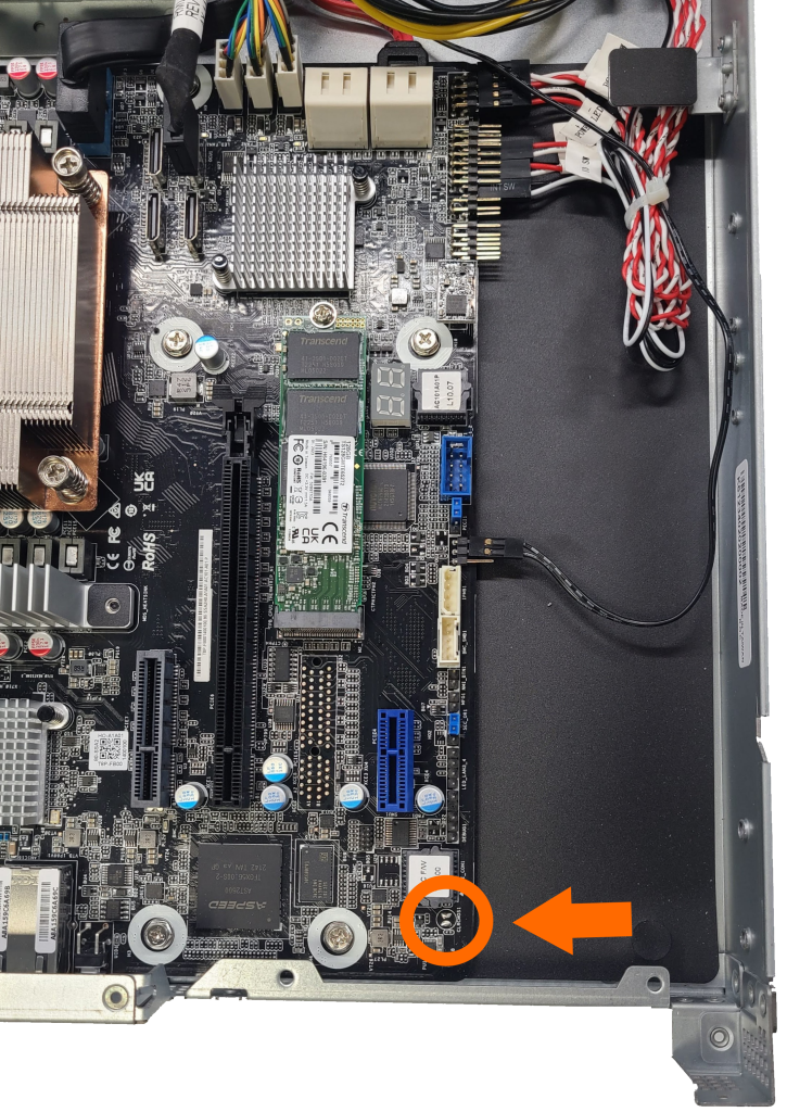
Locate the CMOS pads indicated by the orange circle
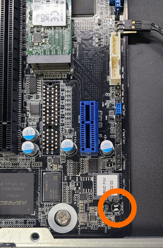
Once you’ve located the CLRCMOS1 pads, use a screwdriver or other conductive tool to short the pads together for at least 30 seconds.
After at least 30 seconds, the CMOS has been cleared. Reassemble the system and power it back up. The unit may restart several times while the motherboard reinitializes.
Reset BMC
In the event the BMC is not-functional, or the CMOS reset does not restore proper functionality to the system, the BMC can be rebooted manually following these steps.
In order to reboot the BMC functionality of the motherboard, locate the “ID” button on the back of the system.

Press and hold the button for at least 5 seconds. This will force a reboot of the BMC chip on the motherboard.
5.2- Security
Cyber Security Advisories
For the latest security advisories concerning OnLogic products, including vulnerability disclosures and necessary updates, please refer to our official Security Advisories page. It is recommended to regularly check this resource for critical security information. Access Security Advisories
Physical Security Features
Security Bezel
The Axial AC101 comes with a security bezel to prevent unauthorized access to front ports and buttons. It is secured by a barrel lock, and a key is included in the accessory package.

Two Point Locking Lid with Intrusion Detection
The chassis lid has a two-point locking mechanism and a built-in intrusion switch.
Locking Points: The first point is a top latch with a tamper-resistant screw, and the second is a thumbscrew at the rear.


Intrusion Detection: If the lid is removed while the system has power, the intrusion switch will detect the event, and the Chassis Intrusion sensor will be asserted and logged in the BMC event log.

5.3- Regulatory
Compliance Information
Do not open or modify the device. The device uses components that comply with FCC and CE regulations. Modification of the device may void these certifications. The use of shielded cables for connection of a monitor to the GPU is required to assure compliance with FCC and CE regulations.
CE
The computer system was evaluated for IT equipment EMC standards as a class A device.
The computer complies with the relevant IT equipment directives for the CE mark.
Modification of the system may void the certifications. Testing includes: EN 55032, EN 55035, EN 60601-1, EN 62368-1, EN 60950-1.
FCC Statement
This device complies with part 15 of the FCC rules as a Class A device. Operation is subject to the following two conditions: (1) this device may not cause harmful interference and (2) this device must accept any interference received, including interference that may cause undesired operation.

ISED
This device complies with Industry Canada license-exempt RSS standard(s). Operation is subject to the following two conditions: (1) this device may not cause interference, and (2) this device must accept any interference, including interference that may cause undesired operation of the device.
Le présent appareil est conforme aux CNR d'Industrie Canada applicables aux appareils radio exempts de licence. L'exploitation est autorisée aux deux conditions suivantes: (1) l'appareil ne doit pas produire de brouillage, et (2) l'utilisateur de l'appareil doit accepter tout brouillage radioélectrique subi, même si le brouillage est susceptible d'en compromettre le fonctionnement.
CAN ICES-003(A) / NMB-003(A)
UKCA
The computer system was evaluated for medical, IT equipment, automotive, maritime and railway EMC standards as a class A device. The computer complies with the relevant IT equipment directives for the UKCA mark.
RoHS

Download Documents
5.4- Appendices
Revision History
5/24/2023
First release of Axial AC101 manual
6/06/2023
Renamed Section 3 to Internal Connectivity, "SSD Header Updates, Drive Placement & Population", 750W PSU recommendation note (when using 150W GPU), Added RAID Configuration (new section 7)
4/30/2024
Updated guidance for FCC and CE regulations when using a GPU Updated FCC statement (added Taiwan and South Korea)
8/12/2024
"Updated Section 1.3 - Product Specifications, Power Supply input specs Added Section 9.5 - RoHS", Updated Section 2.8 - VGA Video
Last updated