This article also applies to the TM710 & TM110 model systems
Drivers and Manual
System Manual
Windows 10 Drivers
Windows 10 Drivers (Follow our guide for Installing via Device Manager)
BIOS Updates
| Version | Link |
|---|---|
| D7870A15.01 | Download |
| D7870A13 | Download |
How to enable auto power on
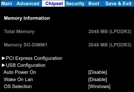
- Power on the CL200 and press the Esc key a few times to access the BIOS
- Navigate to the Chipset tab
- Change auto power on to [enable]
- Save & Exit
- The CL200 will now automatically turn on when power is connected
How to enable Watchdog in Ubuntu (20.04/22.04)
- Enter the BIOS and ensure that the watchdog timer is enabled. The option is at the top of the Advanced settings page.
- Install the watchdog package using `sudo apt-get install watchdog`.
- In the terminal, run `lsmod | grep wdat_wdt` to see if the watchdog module is loaded. If the command returns nothing, the module is not loaded.
- If the watchdog module is not loaded, it is likely blacklisted by default. Open `/usr/lib/modprobe.d/blacklist_linux-hwe-5.19_5.12.0-43-generic.conf` with a text editor and remove or comment out `blacklist wdat_wdt`. If there are other `blacklist_linux…` files here, ensure that the blacklist is removed from them as well.
- Open `/etc/default/watchdog` with a text editor and add or modify the watchdog module line to be as follows: `watchdog_module=”wdat_wdt”`. Other watchdog module settings can be adjusted here as well.
- Open `/etc/watchdog.conf` and add or modify the watchdog device line to be as follows: `watchdog-device = /dev/watchdog `(it may also be `watchdog0`) . There are additional settings here that can be changed as needed, such as the watchdog timeout which controls how long it takes to trigger a system reboot after an event. The timeout defaults to 60s but can be adjusted by adding the line `watchdog-timeout = #` where `#` is the desired time in seconds.
- Reboot the system.
- The following commands should be run as the root user. To confirm the watchdog timer is working correctly, you can kill the watchdog process, stopping the watchdog pulse and causing the system to reboot using the following command: `killall -STOP watchdog`, if `killall` is not available try `pkill -STOP watchdog`. A kernel panic can also be triggered and cause the watchdog to reboot the system using the following command: `echo c > /proc/sysrq-trigger`.
Troubleshooting
Disassembly
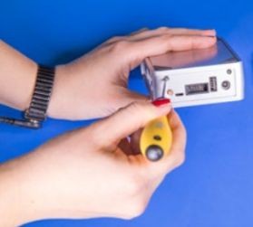
- Remove the two silver Phillips screws
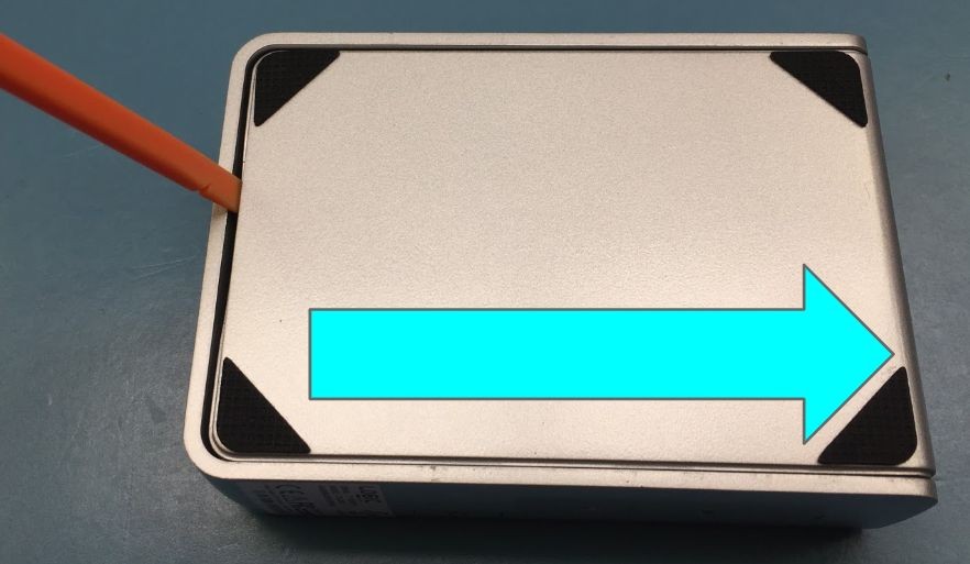
- Use a flathead screwdriver or similar tool to gently lever the bottom cover off
How to clear the CMOS
If the CL200 fails to power on or boot up, clearing the CMOS can help.
Open the system following the Disassembly steps above.
- Locate the Clear CMOS jumpers
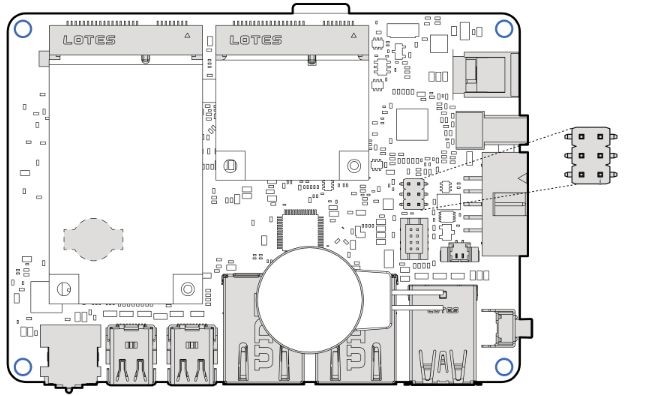
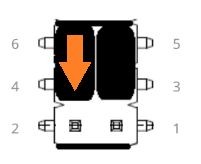
- Remove the black jumper from pins 6 and 4
- Install it onto pins 4 and 2, moving it down by 1 pin
- Wait 30 seconds
- Restore the jumper to its original 6-4 position
- The CMOS is now clear
mSATA/WiFi Card Installation
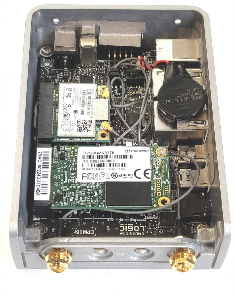
- Open the system following the Disassembly steps above.
- Install the WiFi and/or mSATA card as shown. Install the WiFi antenna pigtail cables as shown.
- The nuts and washers are loose for illustration purposes. They should be fully hand tightened
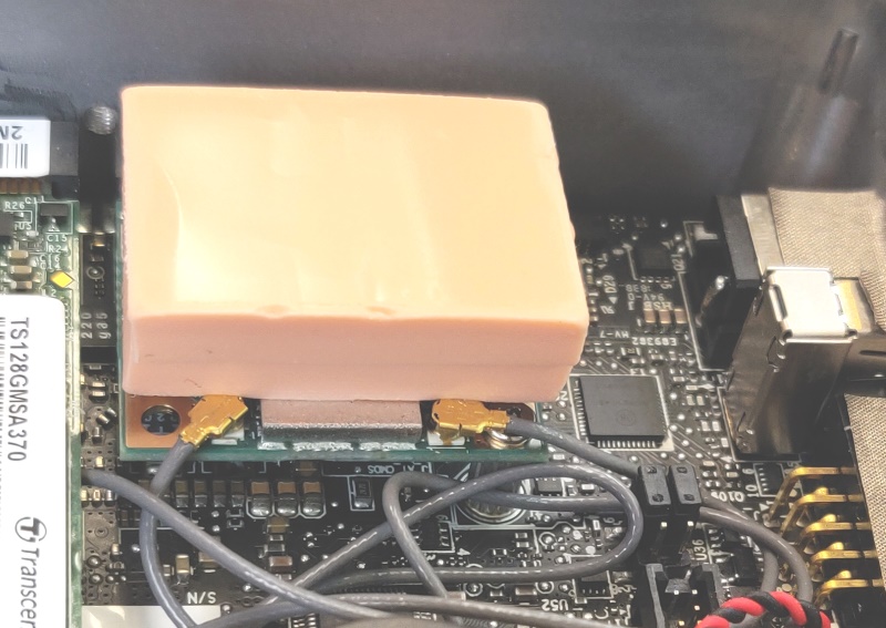
- Apply the thermal pad to the top of the WiFi/mSATA card. This can be located in your system’s accessories.
Reassembly
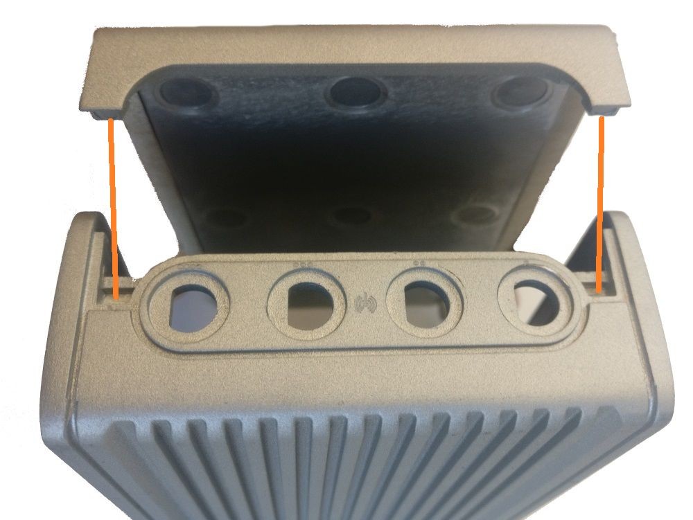
- Hinge the bottom plate back onto the system by aligning the tabs
- Reinstall the silver Phillips screws
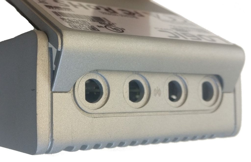
Using the optional CEC module (ADP107)
The ADP107 is a module that is installed in-line with the DisplayPort outputs on configured OnLogic systems. Its purpose is to enable Consumer Electronics Control (CEC) functionality which manages the connection between the system and any connected displays according to a set of preconfigured rules. This allows command signals to be passed to the displays when the computer starts, stops, wakes, and sleeps, in a user-configurable order after a configurable time delay.
Default Behavior
The device’s default configuration is to power up displays when the system starts/wakes and power them off when the system stops/sleeps. It is also configured by default to start the computer when the connected display powers on, and to power the computer off
when the displays are powered off. The default startup delay timer is set to 5 seconds.
Driver Installation
Windows 10
Download the driver archive and extract it.
In the Windows 10 folder, there are two applications required for full functionality, the kernel driver that allows communication with the CEC module, and the user driver that keeps the module up-to-date with the system’s HDMI port addresses.
To install the kernel driver, right-click on ADP107.inf and select install. Accept any prompts that follow, then restart the system.
Linux
Download the driver archive and extract it.
Install the necessary prerequisites using:
sudo apt-get install build-essential linux-headers-uname -r make i2c-toolsIn the Linux folder, you will find a kernel module that can be compiled from the command line.
From the driver package’s Linux folder, run the following commands:
make
sudo make install
Finally, restart the system. Upon reboot, you should find that a character device is loaded at /dev/adp107 that can be used to communicate with the device using the application codes included in the next section.
Application Interface
For information on controlling the ADP107 device, refer to the table in the following PDF.
https://static.onlogic.com/resources/manuals/ADP107-cec-product-manual-OnLogic.pdf
Example Code: Python
Ubuntu – Scan for HDMI addresses and power up displays
Prerequisites: python-smbus
import smbus
smbusNumber = 5
adp107Address = 0x20
physAddrOffset = 0x43
powerOnOffset = 0x4f
powerOffOffset = 0x50
ddcNumbers = [0,1]

def apd107ReadHdmiDdc(ddcNumber):
	bus = smbus.SMBus(ddcNumber)
	rawEdid = []
	hdmiAddress = [ddcNumber]
	for i in range(0, 256, 32):
    	try:
        	rawEdid += bus.read_i2c_block_data(0x50, i, 32)
    	except:
        	print "Failed to read DDC-%" % ddcNumber
        	return None
	if rawEdid[126] == 0: #no extensions after main EDID block
    	return None
	if rawEdid[130] == 4: #no data blocks present in extended EDID
    	return None

	edidIndex = 132
	blockType = 0
	blockLen = 0

	while edidIndex < (rawEdid[130] + 128):
    	blockType = rawEdid[edidIndex] >> 5
    	blockLen = rawEdid[edidIndex] & 0x1f
    	if (blockType == 3): #vendor block containing HDMI physical address
        	hdmiAddress.append(rawEdid[edidIndex+4])
        	hdmiAddress.append(rawEdid[edidIndex+5])
        	return hdmiAddress
    	edidIndex = edidIndex + blockLen + 1


def adp107ScanSetHdmiAddresses(bus):
	for ddc in ddcNumbers:
    	hdmiAddress = adp107ReadHdmiDdc(ddc)
    	if hdmiAddress is not None:
        	bus.write_i2c_block_data(adp107Address, physAddrOffset, hdmiAddress)

def adp107PowerOnDisplay(bus, displayNum):
	bus.write_i2c_block_data(adp107Address, powerOnOffset, [displayNum])

def adp107PowerOffDisplay(bus, displayNum):
	bus.write_i2c_block_data(adp107Address, powerOffOffset, [displayNum])

adp107Bus = smbus.SMBus(smbusNumber)
adp107ScanSetHdmiAddresses(adp107Bus)
#commands are ignored if ScanSetHdmiAddresses didn't find an HDMI address
adp107PowerOnDisplay(bus, 0)
adp107PowerOnDisplay(bus, 1)
Mounting Options
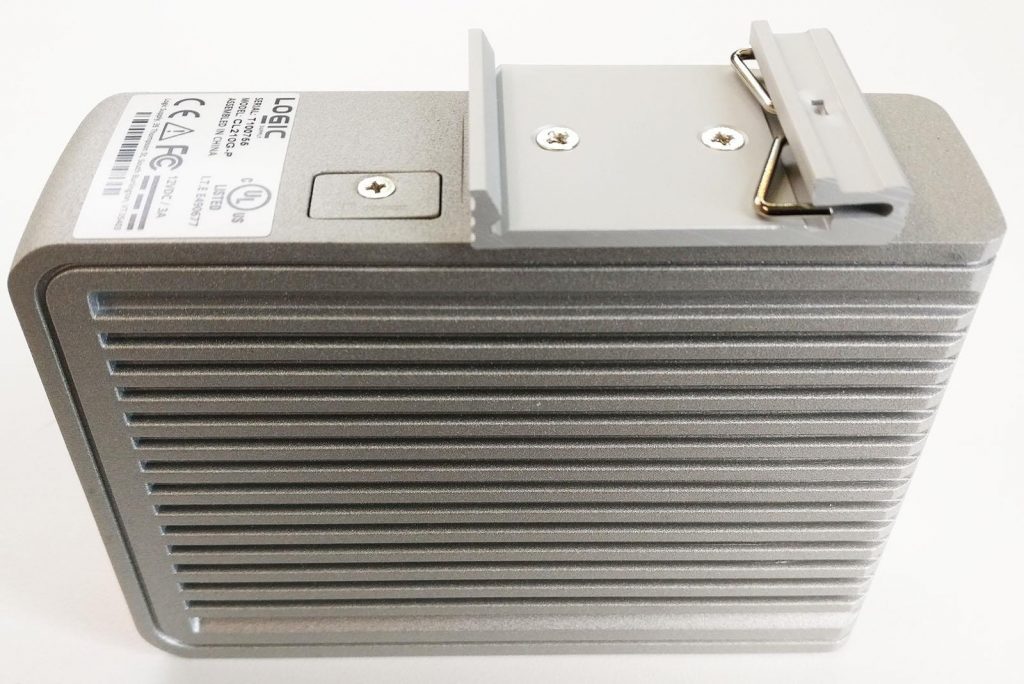
MTD103 DIN mounting
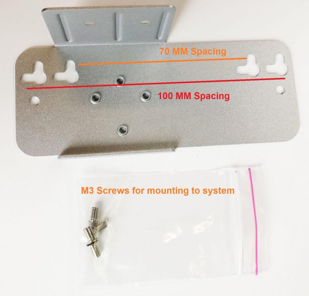
MTW103 Wall and VESA mounting bracket
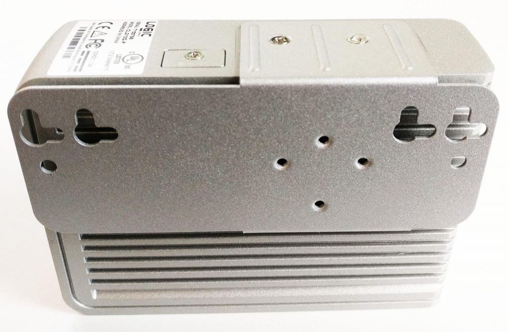
- Secure to wall using M4 screws
