Manual and Documents
K700 Spec Sheet & Dimensional Drawings
Drivers
10Gbe Modbay LAN expansion drivers
BIOS Updates
| Version | Link |
|---|---|
| Z01-0001A040 | BIOS Update (A040) |
Frequently Asked Questions (FAQ)
How do I enable automotive/ignition timings?
The K700 contains a microcontroller which among other things, controls the timings. You can read more on the controller here: https://support.onlogic.com/onlogic-systems/rugged/karbon-series/karbon-series-using-the-serial-interface
How do I configure RAID?
What PoE standards does the optional PoE module support?
802.3at – up to 25.5 watts per port
How do I enable auto power on?
Enter the BIOS and go to Advanced > PCH-IO Configuration > Auto Power-On. See below for a step by step guide.
What orientation is a SIM card inserted?
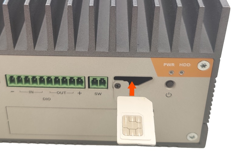
The SIM card can be installed with the contact facing up (toward the chassis fins).
Connecting the power supply
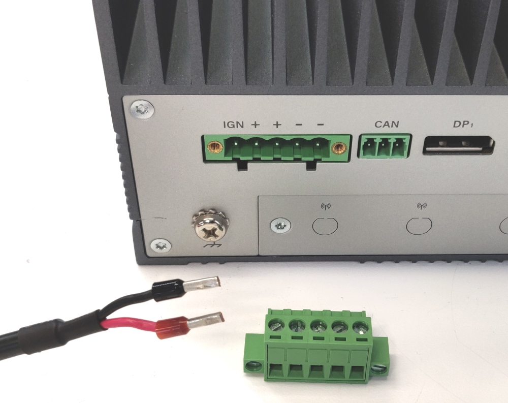
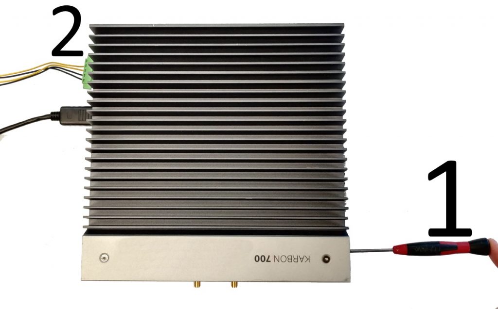
- Unbox the power brick and grab the 5 pin terminal block from the accessory box.
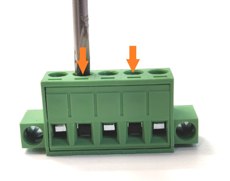
- Using a flathead screwdriver, turn the two indicated screws counter-clockwise a few turns.
- The metal holes at the bottom will open up.
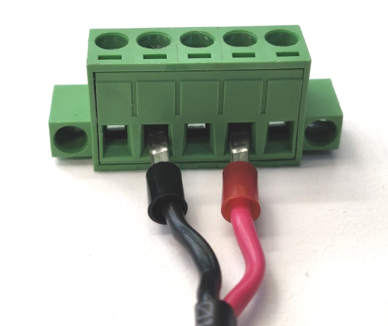
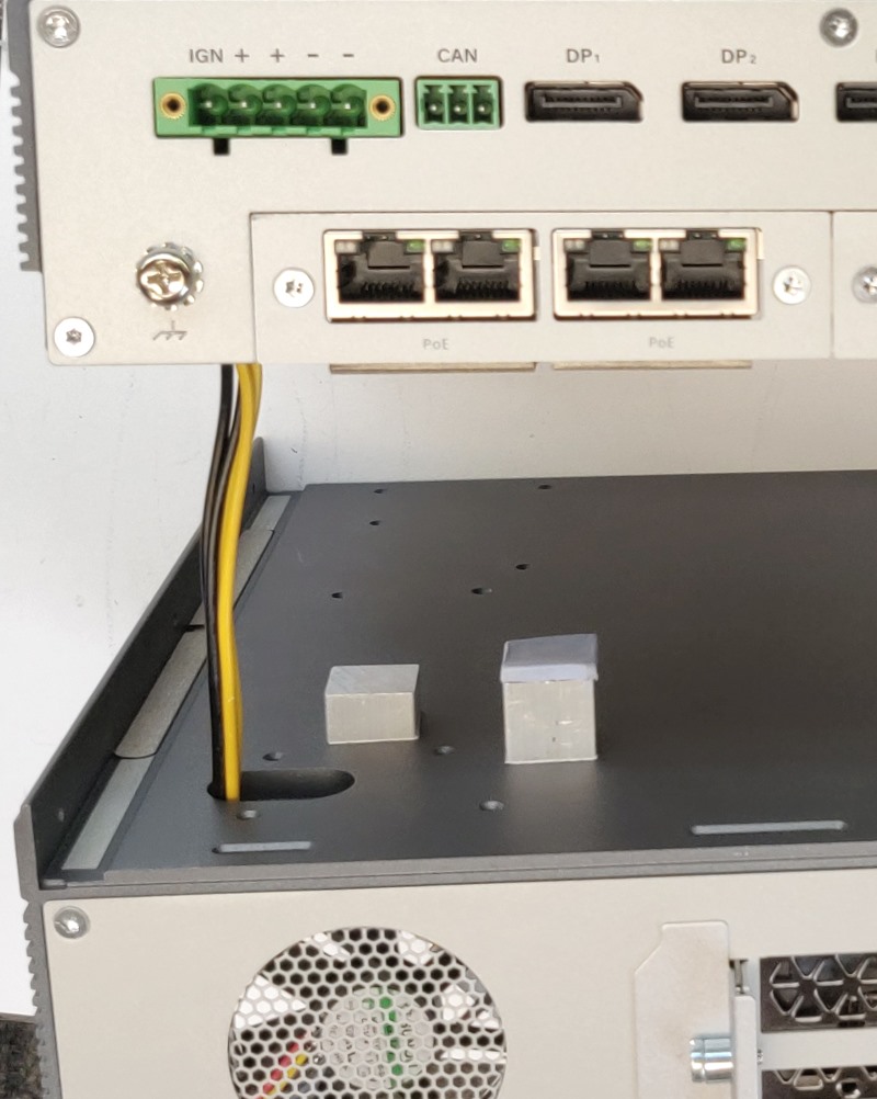
- Insert the power supply wires as shown
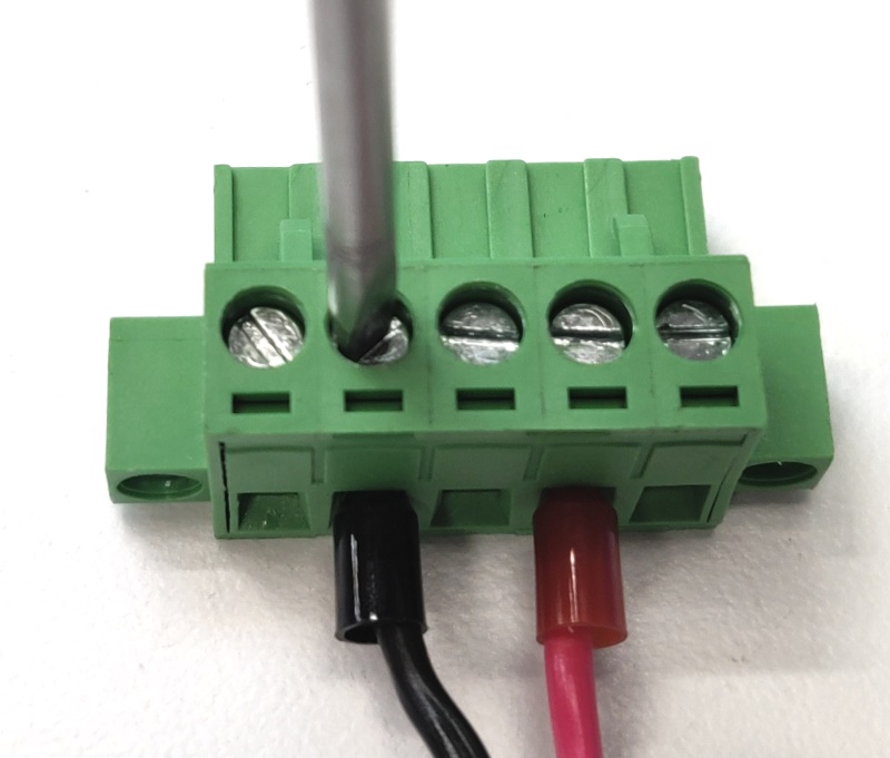
- Turn the screws clockwise to tighten. Firmly hand tighten.
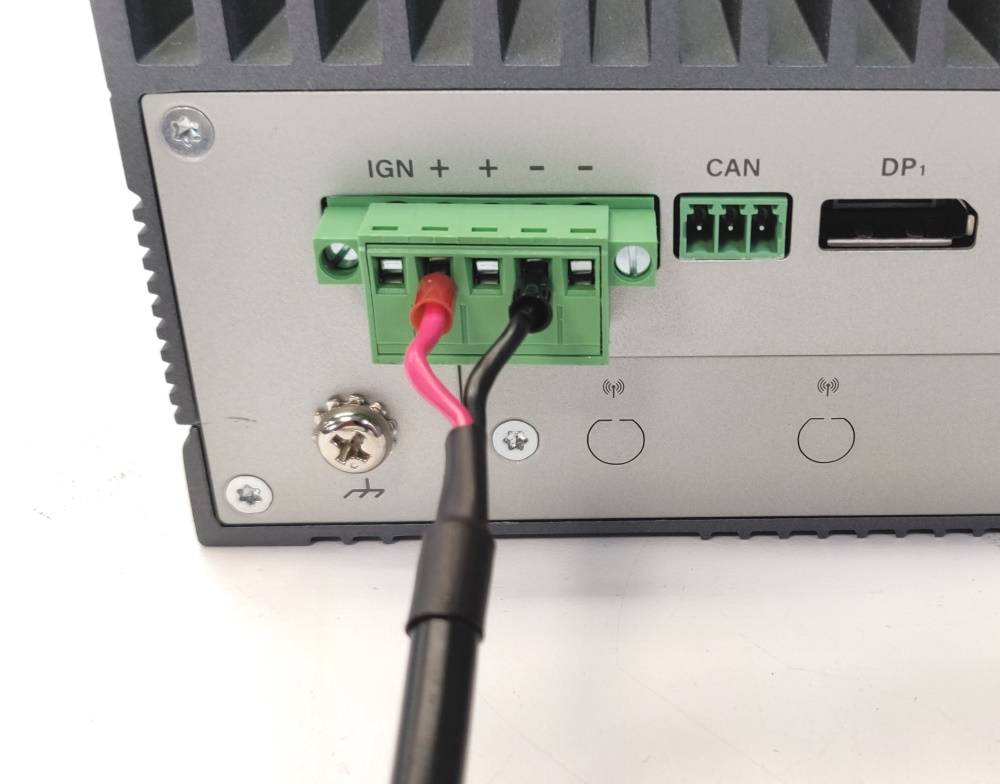
- Connect the green terminal block to the K700. It is now ready for use. Note that the labeling on the back of the system matches the wires you just installed.
- Higher wattage configurations of the K700-X2 may use all 4 wires but they are not needed on the K700-SE model.
System Features
Enabling Auto Power On
Auto power on will automatically turn on the K700 after power failure. This feature can be enabled in the BIOS.
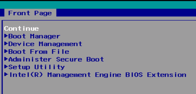
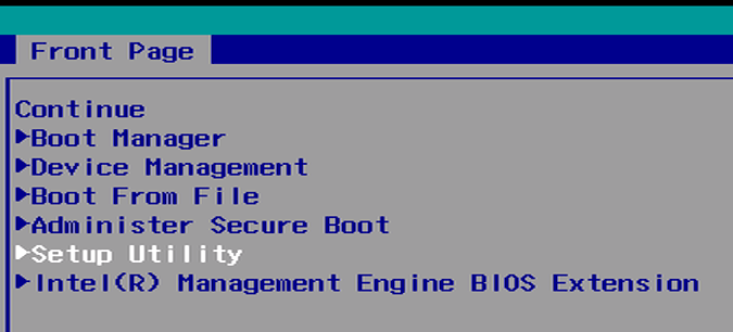
- Power on the K700 and immediately press the Del key a few times until you get the “Front Page” menu
- Use the arrow keys to select “Setup Utility” and press enter
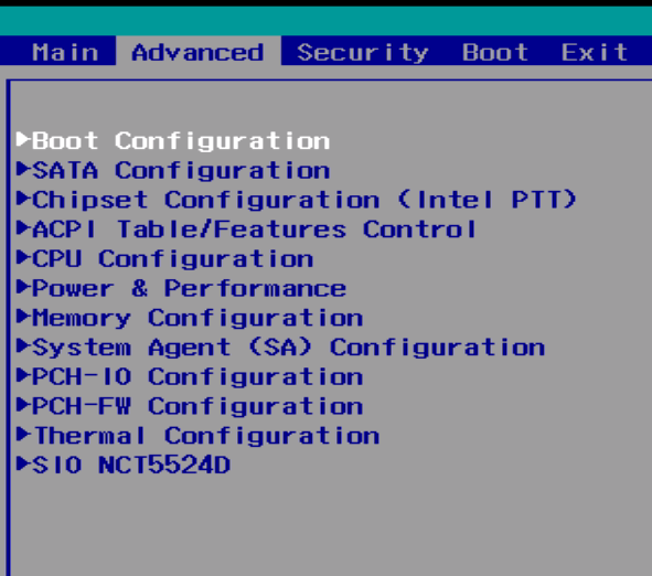
- Navigate to the Advanced tab and open the PCH-IO Configuration submenu
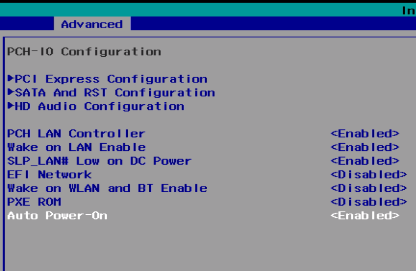
- Change the Auto Power-On opttion to Enabled
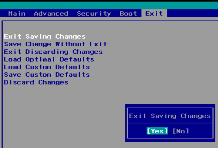
- From the Exit tab, Exit Saving Changes
- Auto power on is now enabled
Ignition Sensing
The Karbon series come with several advanced features that help you make the most out of your applications. One of these features is ignition sensing, a feature that allows you to control your Karbon unit through your vehicle.
So how exactly does ignition sensing work and how is it useful to you?
Ignition sensing on the Karbon series works such that the unit can be powered on or off depending on whether the vehicle itself is on or off. For example, if the vehicle ignition is turned on, the PC unit will power on. Likewise, when ignition is turned off, the PC unit will power off. This process of events can be seen in the timeline below:
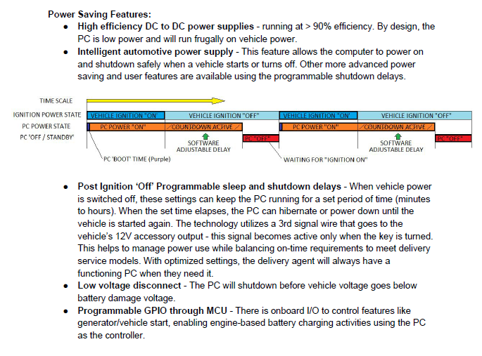
The timeline of events diagram shows ignition power state and the PC power state. Going from left to right, you can see that when the ignition power state is “On” (or the vehicle is turned on), the PC power state enters a PC “boot” time state where the PC boots on. This state lasts only a few seconds, before entering the PC power “on” state, meaning the PC unit is turned on.
When the ignition power state is “Off” (or the vehicle is turned off), the PC power state enters a “countdown active” delay before turning off completely. This delay before the PC unit turns off can be adjusted through OnLogic’s microcontroller (MCU) and can range from seconds to hours.
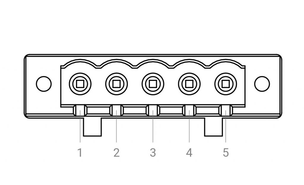
Ignition Sensing is found on the 5-pin power input terminal block for Karbon 700, or the 3-pin power input for Karbon 300, pictured below, where pin 1 is for ignition power on/off.
Ignition timing delays can be modified through serial commands to the MCU using python. The Karbon series come with their own module for interfacing with hardware devices called Pykarbon. To learn about how to use serial commands to change your timing delays on ignition, visit OnLogic’s github page on the Pykarbon module.
Enabling Secure Boot
Secure boot is enabled through the “Front Page” menu.
- Power up the K700 and immediately press the Del key a few times to access the “Front Page” menu
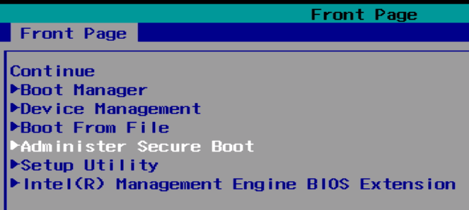
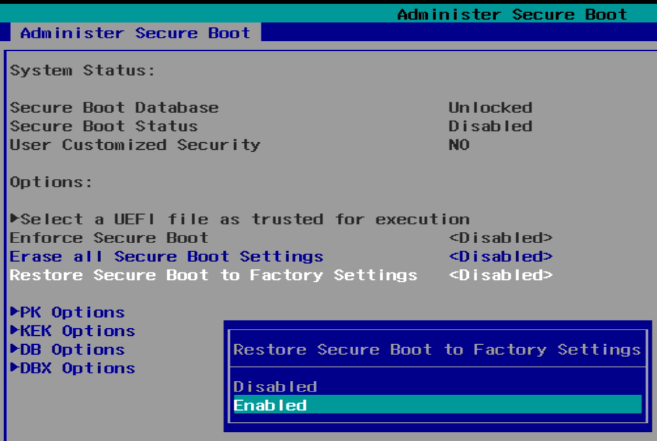
- Open the “Restore Secure Boot to Factory Settings” menu.
- Choose “Enabled”
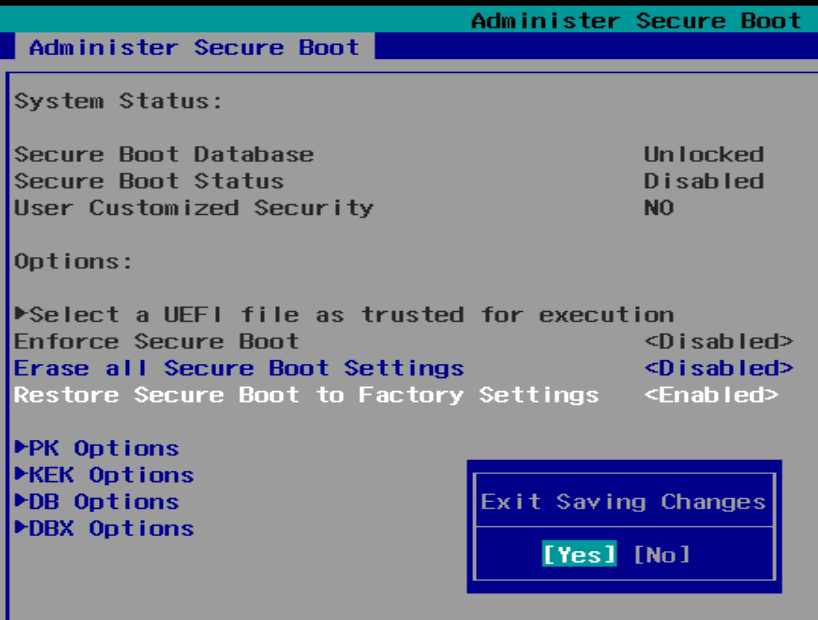
- Press F10 to Save & Exit
- Secure boot is now enabled. Windows should handle key setup, etc automatically.
CAN Bus
CANbus FAQs
The CAN bus on the K300 and K700 series computers can be modified to fit your applications. Here are some of the frequently asked questions regarding the CAN bus feature.
Messages may be sent by writing to the CAN virtual serial port, like this:
std 123 4 11223344 data
The syntax is: [std | ext] [id] [length] [data] [data | remote]
The Karbon series computers additionally support doing some of the legwork for you, and support using a terminal command to interpret and send a packet:can-message 123 11223344
The syntax is: can-message [id] [data]
So just to be clear, you use the first syntax on the CAN serial port, and the second syntax on the serial terminal.
CAN messages are delivered to the CAN virtual serial port. If you are monitoring this port in with a serial terminal, you will see the data printed out in the terminal.
Yes! This is a configuration setting, so you’ll need to access the serial terminal. From there, you have two available commands. The first is:can-autobaud
This command will attempt to detect the baud rate and propagation delay of your CAN bus. It does this by sending messages with ID 7FF, and watching for acknowledgement — so it may not work in every setting. Which is when you want to use the second command:set can-baudrate 800
The syntax is:set can-baudrate [rate](rate is in thousands)
In both cases, you can check if the baud rate was set correctly using config. Don’t forget to save your settings with save-config to ensure that it will persist after a power loss.
If things have stopped working quite right, you can reset the Karbon’s microcontroller and CAN controller by performing a hard power cycle (completely disconnect the system from power). Make sure you shut down normally first!
If something is ever really, really broken, you can force the Karbon series computer to boot in recovery mode by depressing the settings switch while plugging the system in. From here, you should be able to completely re-flash the firmware.
The Karbon series computers have a CAN 2.0B controller.
Getting started
To get started with the basics of communication with the Karbon K300 and K700 units, the command line utility can be downloaded for Linux and Windows systems.
This utility will allow you to work the the Microcontroller which is responsible for the native CAN Bus functionality on the unit. No additional drivers need to be installed to work with the native CAN bus on the system. Although additional python libraries will be needed if you wish to develop python scripts to utilize the native CAN Bus
For this tutorial example we use a K300 running Windows 10 IoT and a K300 running Ubuntu 20.04 with a cable connecting the two units via the CAN Bus port located on the side of the chassis.
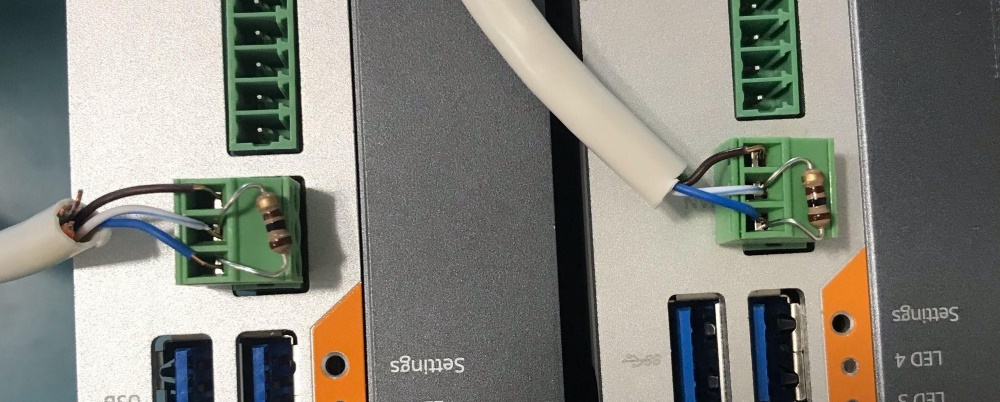
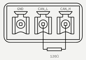
The K300 and K700’s internal CAN device should be attached directly to a CAN Bus, but features no internal termination. Because of this, for proper operation, it may be required to implement an external termination resistor. This resistor should match the nominal impedance of the cable; typically 120Ω, which complies with ISO 11898.
Using the Microcontroller CLI utility to send CAN Messages
Sending CAN messages from Windows to Linux system
After downloading and extracting the Windows directory from the Microcontroller Utility, open command prompt and navigate to the directory containing the Karbon.exe CLI utility. From here you can use the command karbon.exe raw devices
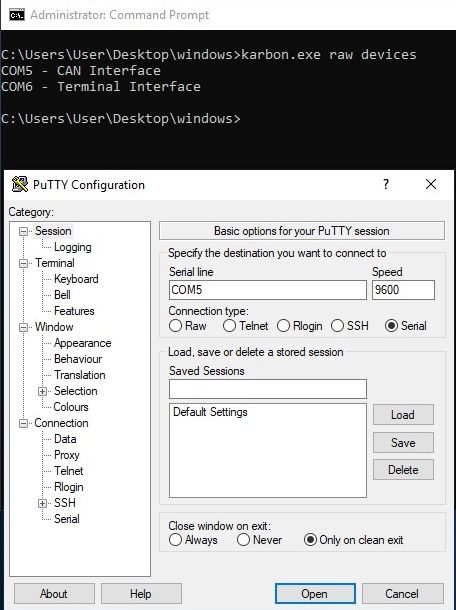
We can then use PuTTY to open the CAN interface port and now the PuTTY terminal is listening to the CAN interface of the Microcontroller.
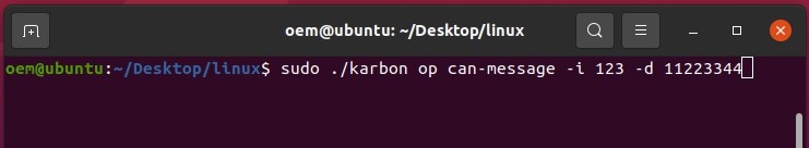
To prep a Linux system to receive these messages, we can extract the Karbon MCU utility’s Linux directory and navigate to it. Running the Karbon utility with sudo, we can send normal CAN Frames over the systems CAN Bus using the sudo ./karbon op can-message -i 123 -d 11223344 command
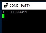
The Windows machine’s PuTTY Window will receive and present the sent CAN message
Sending CAN messages from Linux to Windows system
The Linux Microcontroller CLI utility can report which /dev/ address is handling CAN communication with the command sudo ./karbon raw devices
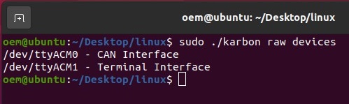
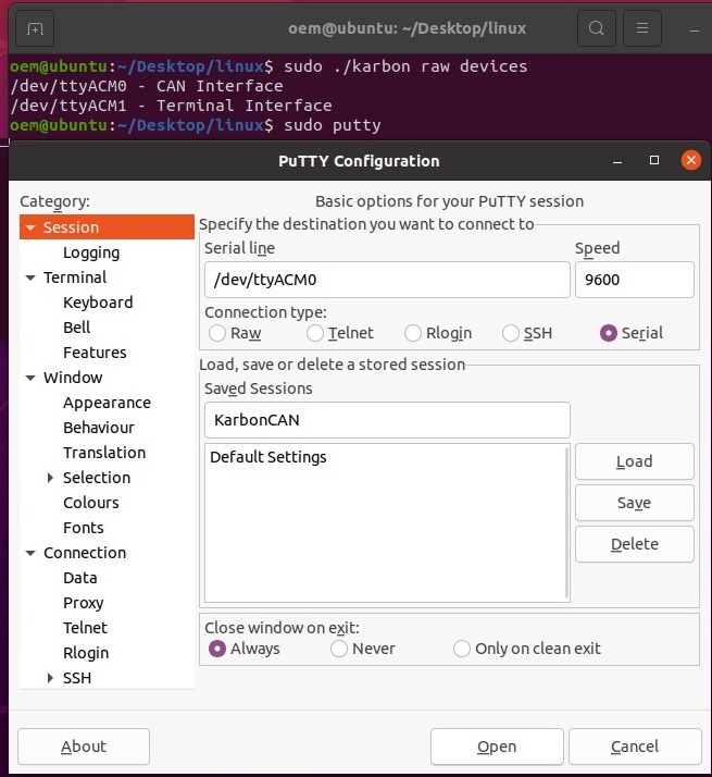
The CAN interface can be opened with an elevated PuTTY command to listen for CAN messages.
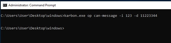
On the Windows system using an elevated command prompt, CAN messages can be sent utilizing the karbon.exe op can-message -i 123 -d 11223344 command.
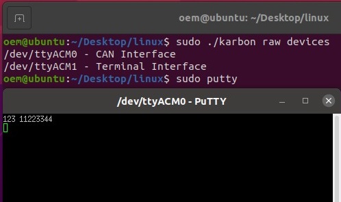
The CAN message will show up on the Linux system’s PuTTY window
Microcontroller Utility
The can subcommand supports interfacing with and controlling the onboard CAN device. This includes sending and receiving CAN messages and setting the baudrate of the CAN Bus. This module requires the CAN device be configured standard operational mode. The mode of the CAN device is controlled by the can-mode configuration parameter.
The CAN device does not support internal termination, and should be externally terminated when connected to a CAN bus.
Using SLCAN
The K300 and K700 platforms also support processing CAN commands using an slcan compliant parser. To get up and running with slcan on a K300 or K700 running Ubuntu, start by installing can-utils:
$ sudo apt install can-utils
Then detect and set up the system, for example:
slcan_setup.sh
#! /bin/bash

# ASCII Command vs CAN Bitrate
# s0 --- s1 --- s2 --- s3 --- s4 --- s5 --- s6 --- s7 --- s8
# 10     20     50     100    125    250    500    800    1000  Kbits/s
BAUD=8

# Name of slcan device to attach
DEV=can0


# Detect correct port for device interfaces
TERM_PORT=$(ls -l /dev/serial/by-id/ | grep 1fc9_00a3 | sed 's/.*\///g' | awk '{if(NR==2) print $0}')
CANB_PORT=$(ls -l /dev/serial/by-id/ | grep 1fc9_00a3 | sed 's/.*\///g' | awk '{if(NR==1) print $0}')

# Start or stop the service
while getopts ":ks" opt; do
    case $opt in
        k)
            # Stop the SLCAN service and turn off the can device
            echo "Shutting down can interface..."
            sudo ifconfig $DEV down 2> /dev/null
            sudo pkill slcand

            sudo slcand -c /dev/"$CANB_PORT"
            sudo pkill slcand
            ;;
        s)
            # Open the can device, and start the slcan service.
            echo "Terminal interface on: $TERM_PORT"
            echo "CAN Bus  interface on: $CANB_PORT"

            # Set the mode to slcan
            echo -ne "set can-mode slcan" > /dev/$TERM_PORT

            echo "Attaching slcan device..."

            # Attach to the port with slcand
            sudo slcand -s$BAUD -o /dev/"$CANB_PORT" $DEV

            # Give interface time to come up
            sleep .25

            # Enable the inteface
            sudo ifconfig $DEV up
            sudo ifconfig $DEV txqueuelen 1000

            echo "Interface is set up."
            ;;
        \?)
            echo "Invalid option: -$OPTARG" >&2
            exit 1
            ;;
        :)
            echo "Option -$OPTARG requires an argument." >&2
            exit 1
            ;;
    esac
done
The system is now ready to send and receive can messages using can-utils:
$ cansend can0 123#11223344
$ candump can0
By default, the can subcommand will first check the operational mode before sending a command. Because this is slower than just sending or receiving can messages, and requires access to the terminal port, it can disabled with the --nocheck flag.
Don’t check can mode
$ karbon can -n <COMMAND>
Additionally all can operations support setting the baudrate before processing the command. This requires access to the terminal serial interface, and does not change the baudrate that will be loaded at system boot. If no baudrate is specified, the last transmitted baudrate will continue to be used.
Specify can baudrate
$ karbon can -b 500 <COMMAND>
The baudrate is specified in Kbits/s, and supports setting rates from 100-1000.
Can Commands
The Microcontroller CLI supports sending and receiving can messages with two commands: send and dump.
Send
The send command supports sending standard, extended, and remote frames. All messages require an id. Standard and extended frames also require data. Standard frames are sent by default, while extended and remote frames can be sent by using the corresponding flag.
Usage
$ karbon can send [FLAGS] [OPTIONS] <identifier> [data]
| Argument | Description | Type |
|---|---|---|
data | The data to be transmitted, represented as an up-to eight byte hex string. Passed data will be checked for validity before transmission. This argument is required, except when sending remote request frames (-r).Example$ karbon can send 123 1122334455667788 | arg |
identifier | The ‘id’ of the can frame. Should be specified as hex string from 1-7FF for standard frames, and 1-1FFFFFFF for extended frames.Lower numbered frames will have priority during message arbitration, and by default, the id will be interpreted as a standard frame id.Validity checking will be performed against the hex string and id range. | arg |
extended | Send message in extended frame format. Supports larger id range.Example$ karbon can send -e 999 11223344 | flag |
length | Length of data to be transmitted. If not specified, the data length will be automatically determined.Example$ karbon can send -l 3 123 112233 | opt |
remote | Send a remote frame. When specified, data is not required.Example$ karbon can send -r 123 | flag |
Validity Checking
The send command’s id and data arguments are specified as strings, and parsed into hexadecimal. Because of this, validity checking is performed against the specified ID and data, before the command is passed on to the microcontroller. In psuedo-code the checks performed are as follows:
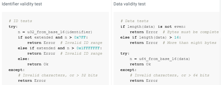
Additionally, it is acceptable to specify id or data with a leading 0x, which will simply be trimmed before data validation is performed.
Dump
The dump command supports reporting all received CAN messages. Messages may be filtered by id, and the time between frames can be recorded.
By default, the messages will be formatted and printed to stdout, but the data can also be reported in csv format and/or saved to file.
For instance, to print all messages to the terminal along with their time delta, run:
$ karbon can dump -d
Or to log only messages with a matching id to messages.csv, run:
$ karbon can dump -d -c -f 123 7FF -- messages.csv
Usage
karbon can dump [FLAGS] [OPTIONS] [--] [output]
| Argument | Description | Type |
|---|---|---|
csv | Format the output as a csv. Does not redirect output from stdout. Header will be included as id,len,data or as id,len,data,delta.Example$ karbon can dump -c id,len,data 123,4,11223344 | flag |
delta | Log the time delta between frames. Times will be reported as floating point seconds; 1.001 is 1001 milliseconds.Time delta is calculated at the host, and should not be considered a perfect representation of time between frames.Example$ karbon can dump -d id [l] data delta 123 [4] 11223344 2.907689 7FF [4] ABCD 3.386151 123 [4] 11223344 6.232194 00000999 [8] 1122334455667788 0.000519 | flag |
filter | A list of CAN frame identifiers to match received messages against. All other messages will be discarded.ImportantExtended IDs should be specified in their full form, including leading zeroes. E.g. 00000999 not 999.Example$ karbon can dump -f 123 1FFFFFFF 00000999 3AA | opt |
output | The output location for printing CAN frames. Defaults to stdout when not specified. | arg |
Disassembly Instructions
K700-SE
Required tools: Torx T10 Driver, P2 Phillips Driver
Opening the K700 does not void the manufacturer’s warranty. However, some precautions are necessary to avoid damaging the unit.
- Perform this disassembly in an area free of static discharge
- Before beginning, touch a grounded metal surface to discharge your body of static electricity
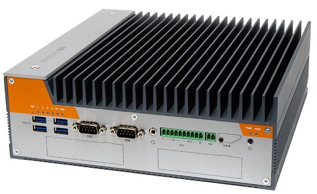
- Remove the 6x case screws from the sides of the K700 and lift away the bottom cover.
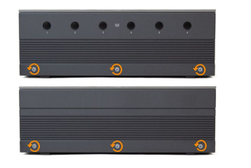
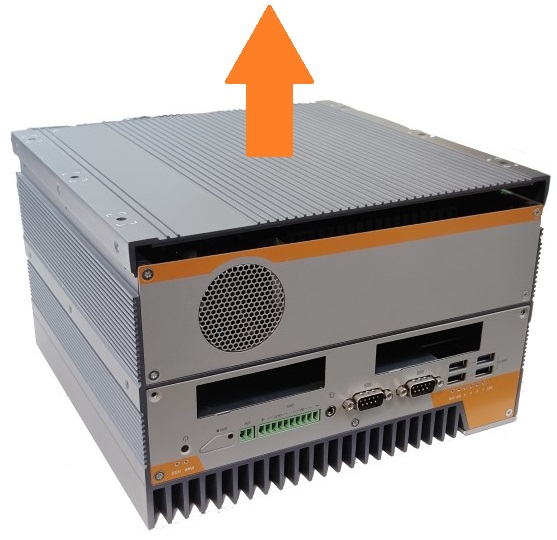
- Pull the metal shroud upward out of the case. Tip: grab it by the metal tabs.
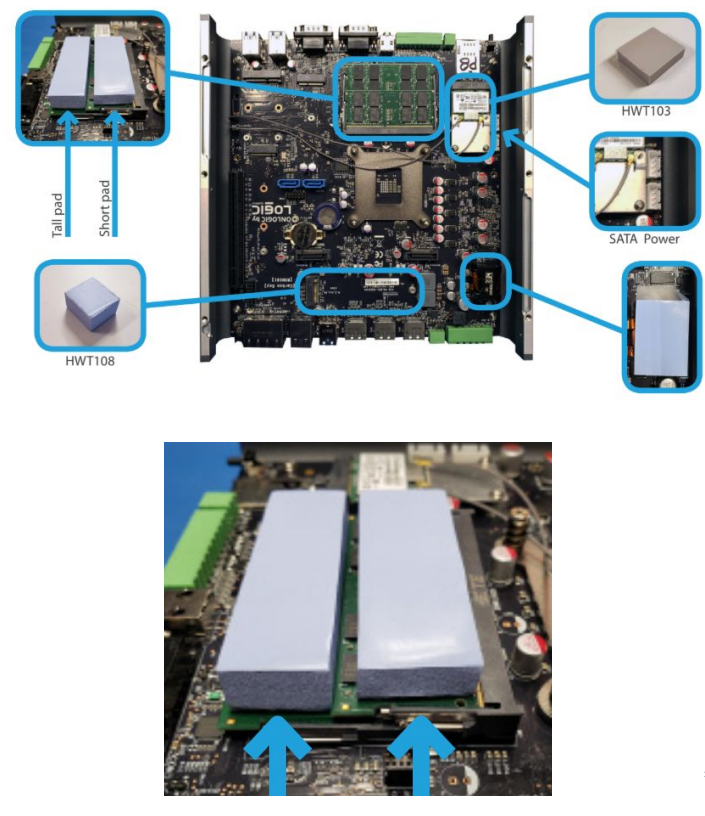
The motherboard is now accessible. The figure below details the different thermal pads required from add-on components.
K700-X2
Required tools: Torx T10 Driver, P2 Phillips Driver
Opening the K700 does not void the manufacturer’s warranty. However, some precautions are necessary to avoid damaging the unit.
- Perform this disassembly in an area free of static discharge
- Before beginning, touch a grounded metal surface to discharge your body of static electricity
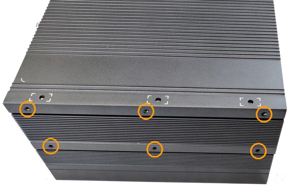
- Remove 6x torx screws from both sides of the unit.
- Lift away the bottom cover
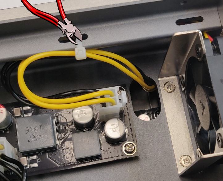
- Carefully cut the zip tie on the power wire and unplug it from the power board. (If equipped)
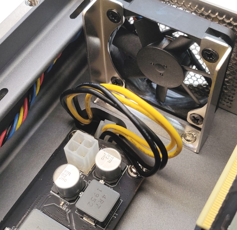
- Tuck the power connector into the cutout.
- It will be pulled through when you remove the X2 module in the next step.
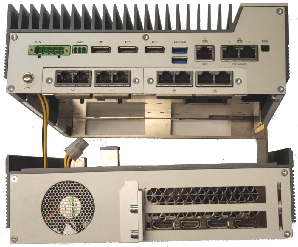
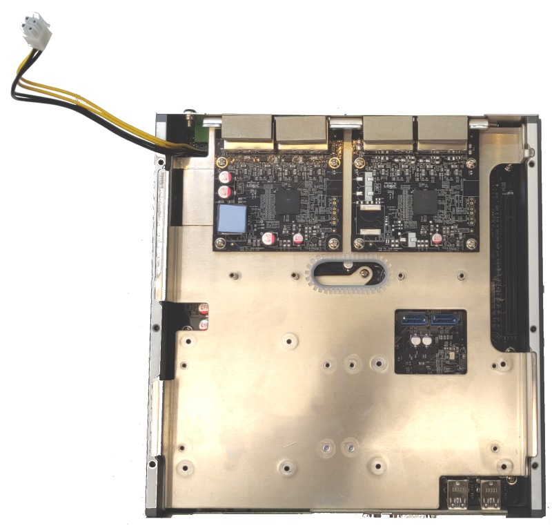
- Pull the X2 Module off of the unit. Moderate force may be required.

- The modbay cards and 2.5″ drives are now accessible.
- Pull the metal shroud upward out of the case. Tip: grab it by the metal tabs.
The motherboard is now accessible. The figure below details the different thermal pads required from add-on components.
Reassembly
- Drop the metal shroud back into place. Press downwards in the middle to ensure it is fully seated.
- Feed the power wire back through the cutout and firmly press the X2 module into place.

- Reinstall the Torx screws
Troubleshooting
Clearing the CMOS
If the K700 fails to power on or otherwise function, clearing the CMOS may help restore it to a working state. The CMOS must be reset via this method – removing the battery will not work due to the supercap feature.
- Unplug the system from all power and peripherals and perform the disassembly steps above.
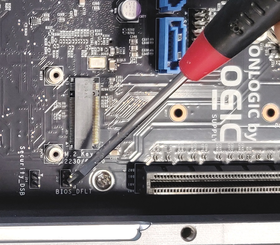
- Locate the BIOS_DFLT jumper
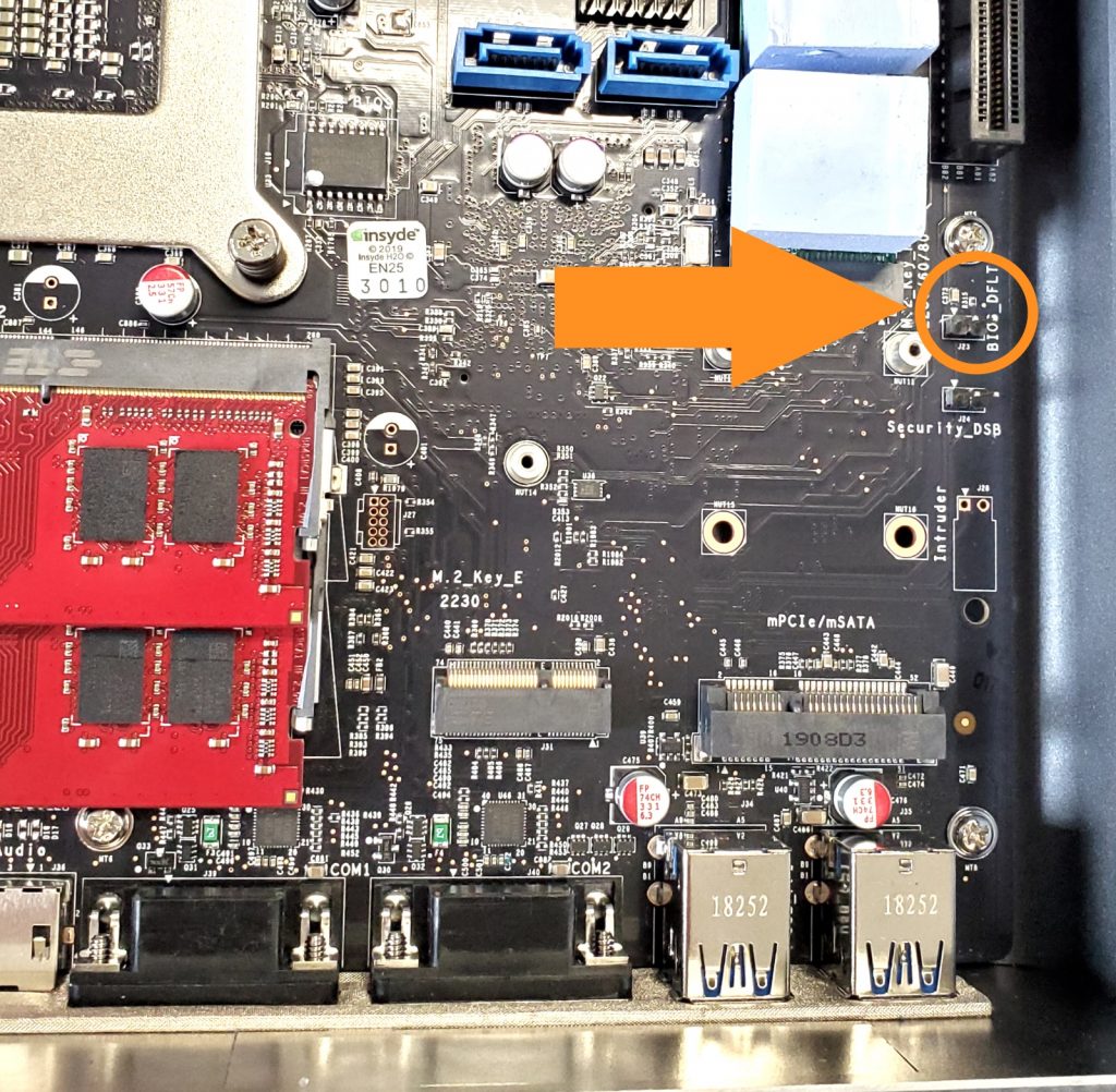
- Short the two pins for 30 seconds with a conductive object such as a screwdriver
- The CMOS is now clear. Reassemble and power on the unit. It may reboot several times before displaying video.
- If the unit still fails to function, contact technical support.
Resetting the MCU (Microcontroller)
The MCU is responsible for many of the basic functions of the K700. Resetting it can resolve video and boot issues.
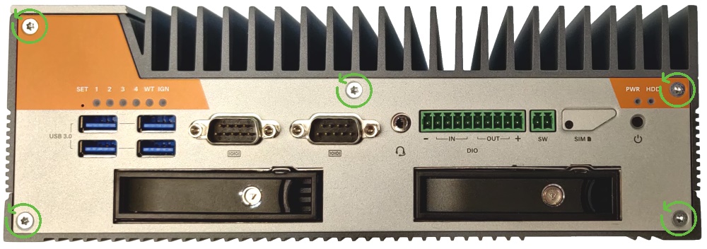
- Begin by removing the 5 Torx T8/T10 screws from the front plate
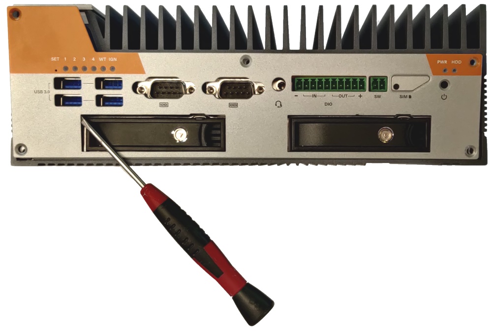
- Gently pry the front plate off and set it aside
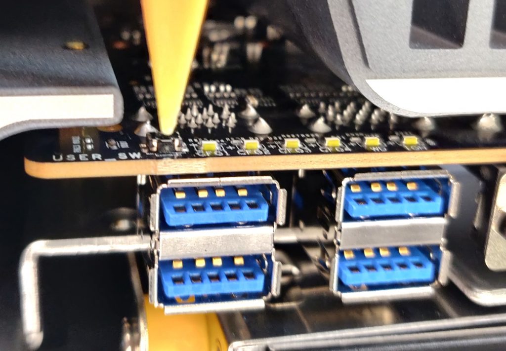
- Locate the MCU reset switch above the USB ports
- Press and hold the reset switch while plugging in the system.
- With the switch still held down, press the power button to turn on the system.
- The WT LED should begin flashing rapidly, indicating the MCU is now in recovery mode.
- It is recommended to reflash the firmware at this point to restore factory settings.
- The MCU will return to normal operating mode automatically the next time the system is unplugged.
Can’t access the BIOS, System loads straight into the OS
The system supports Fast Boot, which is a configurable BIOS setting. With Fast Boot enabled, the unit will disable booting to Network, Optical, and USB/removable drives. Video and USB devices (such as keyboards) will not initialize until the OS loads. This can make it difficult to reinstall an OS, or change any BIOS settings, and make the BIOS harder to access. To enter the BIOS follow the steps below for your specific OS.
Windows
From the Start Menu, hold Shift and click Restart to access the Recovery screen, then go to “Advanced” and select “UEFI Firmware Settings”. The system will reboot and allow access in the the BIOS. You may need to repeatedly press DEL/F2 keys while the system is rebooting.
Linux
From Terminal, run the following command:systemctl reboot --firmware-setup
This will trigger the system to reboot and allow access into the the BIOS. You may need to repeatedly press DEL/F2 keys while the system is rebooting.
Once you’ve accessed the BIOS, you can find the Fast Boot setting under the Boot tab.
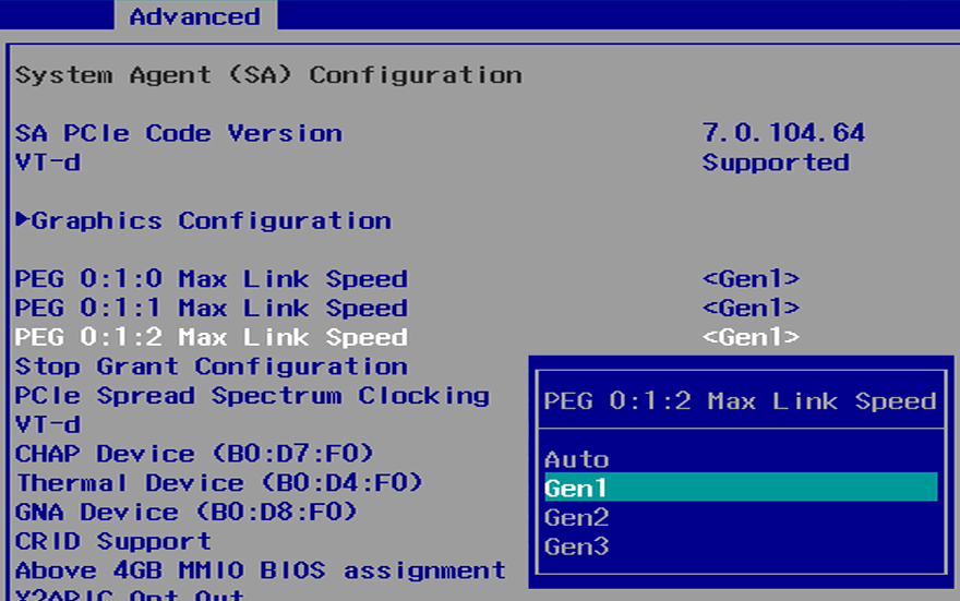
PCIe card not detected properly
Older PCIe cards may require the speed to be set manually. This is recommended for a Gen1 or Gen2 card. 3.0 cards should work out of the box.
Manually setting the PCI-E generation
- Power on the unit and immediately press the Del key a few times to access the Front Page
- Enter the Setup Utility
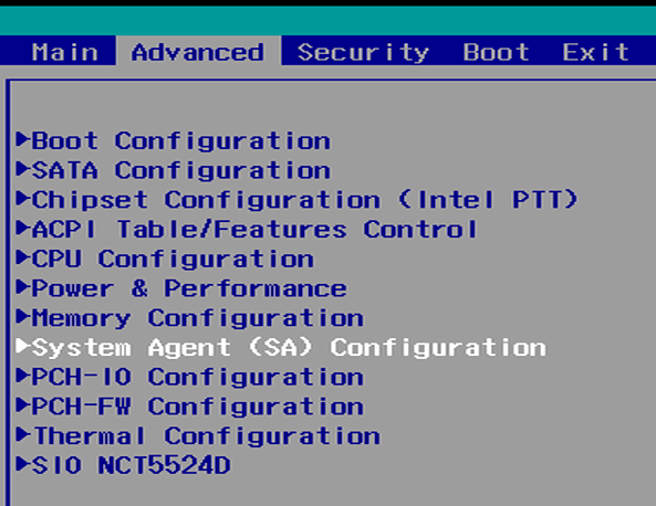
- In the Advanced tab, open the System Agent (SA) Configuration
- Change all 3 PEG Link Speed options to Gen1 or Gen2 to match your card.
- Press F10 to save and exit
Installation of Parts
Din Mounting Kit Assembly
MTW106 & MTD103
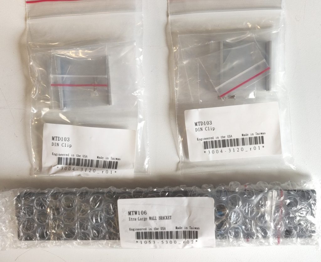
- Remove the 2x DIN clips and the mounting bracket from the accessory box
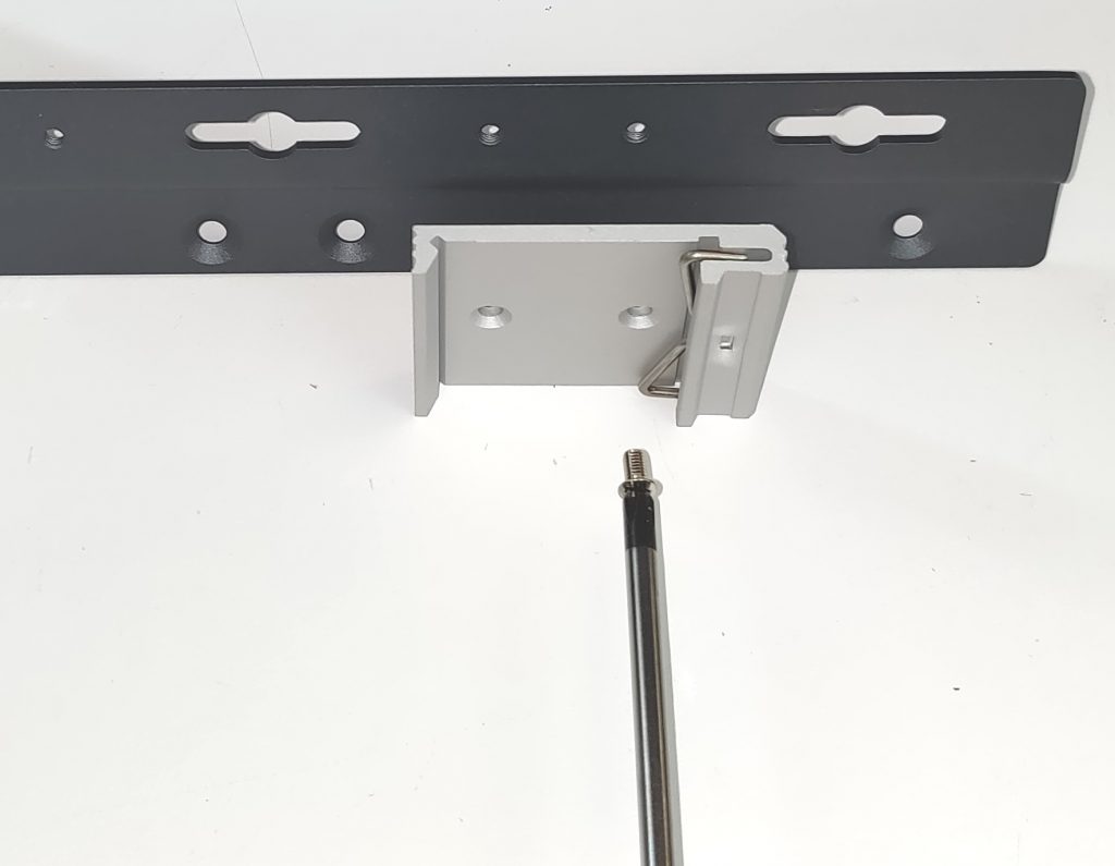
- Install the DIN clips onto the brackets using the small screws that came with the clips.
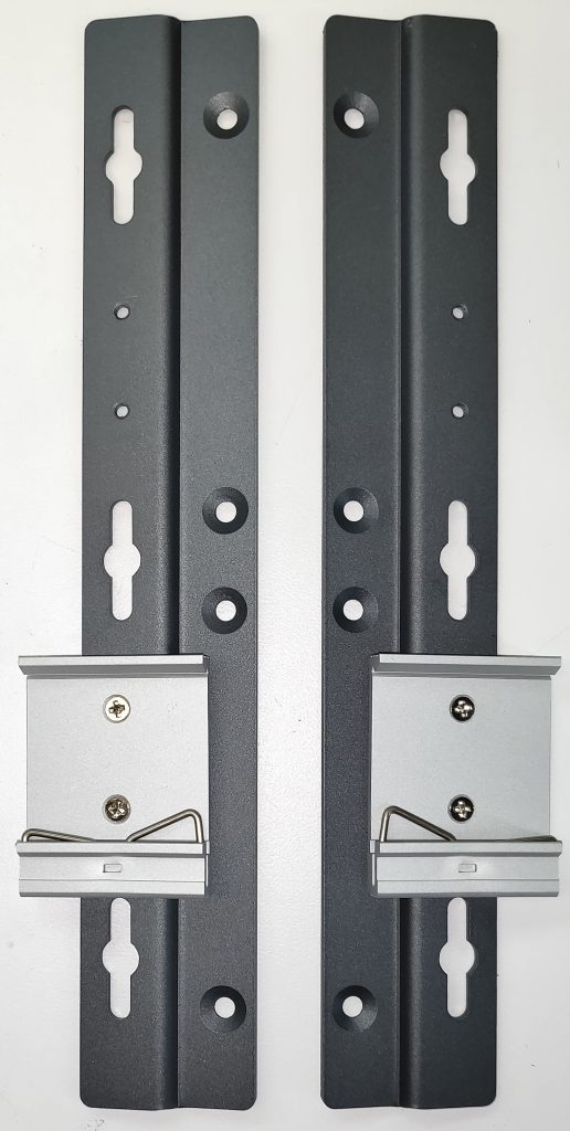
- Align clips as shown
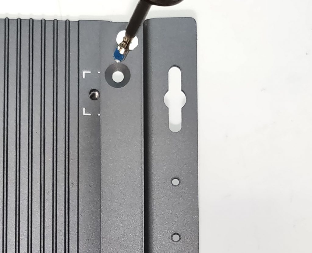
- Install the mounting brackets to the bottom of the K700
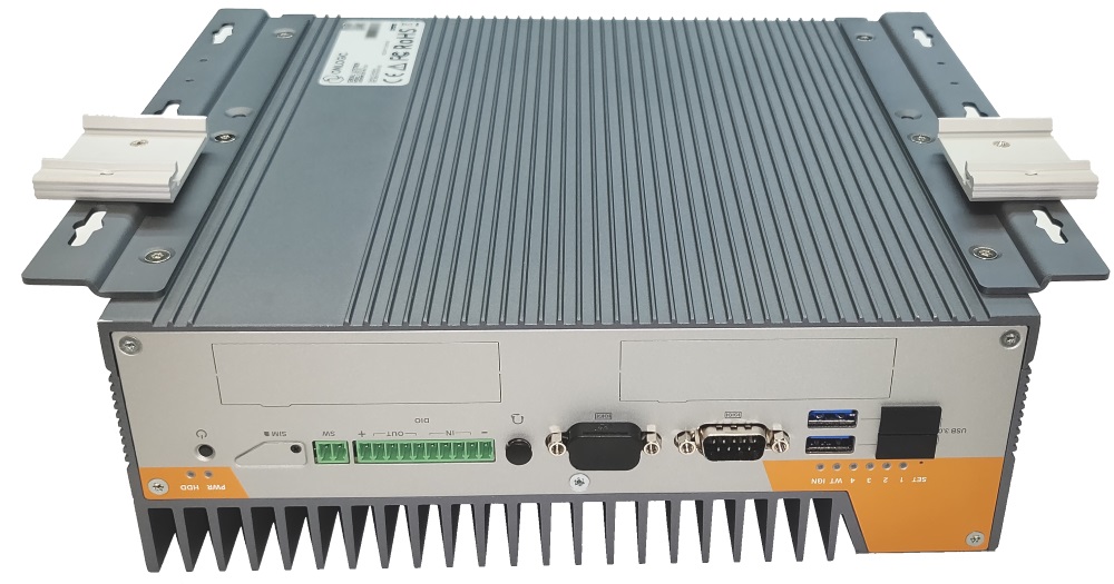
- Final assembly shown
External Fan
Installing the optional External Fan
The external fan is an optional add-on for the K700 & K800 series, which provides active cooling. This adds a 120mm case fan and moves approximately 110 CFM of airflow.
The K700 and K800 series use the same external fan. It can be installed by removing the branding plate (on the top of the system) and installing the following screws:
- x2 on the top (under the branding plate)
- x1 on the side
The external fan uses a magnetic dust filter. The filter should be cleaned regularly. If the filter is misplaced, our replacement part SKU is FANCPD-MESH. This can be ordered by reaching out to our sales team.
Installing the PoE module
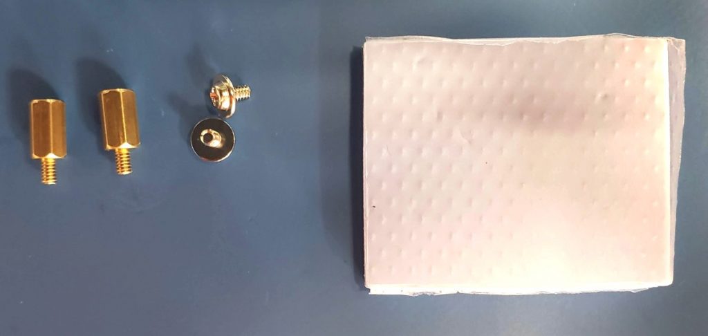
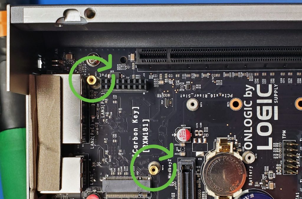
- Install the standoffs. Gently hand tighten – they are fragile.
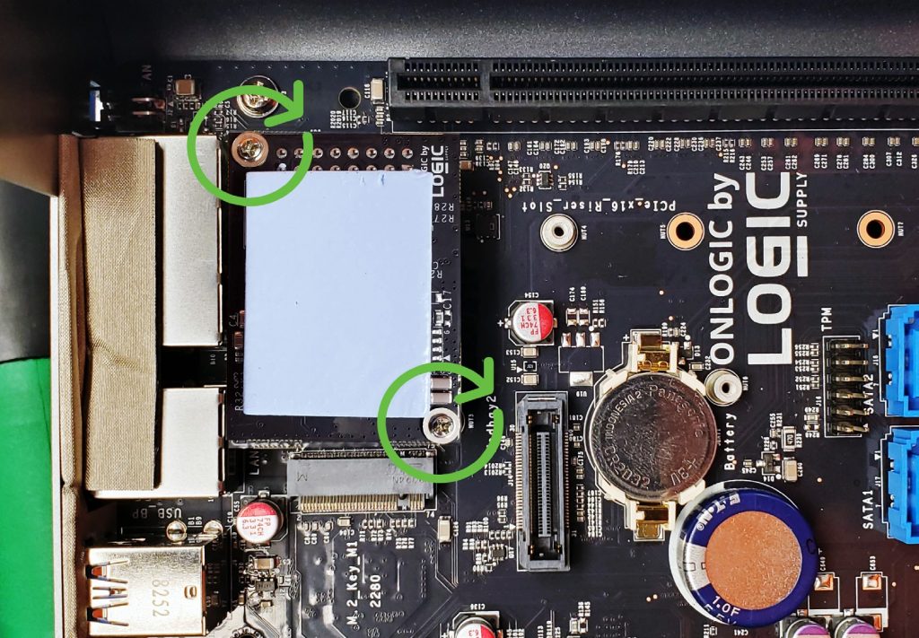
- Install PoE module onto connector. Double check that the pins align.
- Install 2x screws
- Peel and stick thermal pad